1
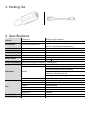
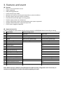
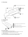
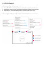
G7S User Manual v1.0 Copyright © 2014 Gosafe ATTENTION Do not disassemble the device. Do not touch before unplugging the power supply if the device is damaged, the power supply cables are not isolated or the isolation is damaged. All wireless data transferring devices produce interference that may affect other devices which are placed nearby. The device may be connected only by qualified individuals. The device must be firmly fastened in the predefined location. The device is susceptible to water and humidity. INSTRUCTIONS OF SAFETY This chapter contains information on how to operate “G7S” safely. BY following these requirements and recommendations you will avoid dangerous situations. You must read these instructions carefully and follow the strictly before operating the device! The device uses a 8V-32V DC power supply. The nominal voltage is 12V DC. It is advised to transport the device in an impact-proof package. Before usage, the device should be placed so that its LED indicators are visible, which show what status of operation the device is in. When connecting the connection cables to the vehicle, the appropriate jumpers of the power supply of the vehicle should be disconnected. Before dismounting the device from the vehicle, the connection must be disconnected. LEGAL NOTICE Copyright © 2014 Gosafe. All rights reserved. Reproduction, transfer, distribution or storage of part or all of the contents in this document in any form without the prior written permission of Gosafe is prohibited. Other products and company names mentioned herein may be trademarks or trade names of their respective owners. INTRODUCTION With accurate GPS location performance, a robust programmable rules engine, 3 axis accelerometer for measuring driver behavior and vehicle impacts, geo-fencing, messaging and much more, the G7S is designed for powerful solution deployment. The G7S is powered by over-the-air device management and maintenance system, (Programming, Updates, and Logistics System). FOTA (Firmware update over the air), GSM Jamming detection and 156 hardware based geo-fences makes this the perfect choice for superior safety and security of your vehicle. Contents 1. Packing list .............................................................................. 4 2. Specifications .......................................................................... 4 3. Features and event.................................................................. 5 4. Overview ................................................................................. 6 5. Installation ............................................................................... 6 5.1. SIM card ............................................................................. 6 5.2. Sensor calibration ............................................................... 6 6. LED behavior ........................................................................... 7 7. User command ........................................................................ 8 8. Message sample .................................................................... 11 1. Packing list 2. Specifications 108(L)*32(W)*32(H)mm ~60g (With backup battery) -40℃ to +80℃ (without backup battery) Environment Operating temperature -10℃ to +50℃ (with backup battery) Interface Cigarette lighter Nominal 12VDC USB Mini USB 2.0 CPU ARM STM32F103 LED indicator 3 LED indicators GSM & GPS & POWER External DC 8 to 32V Power supply Backup battery Type Rechargeable, Li-Po 3.7V, 250mAh Power consumption Standby: 33mA@12V, Operating: 130mA@12V Antenna Built-In Cinterion BGS2-W Quad band: 850/900/1800/1900MHz GSM/GPRS Model Multiple-slot Class 8 (dual band)/10 (quad band) GPRS class 10/Station class B TCP/IP over PPP SIM card 1.8V & 3.3V Internal antenna 25*25mm with amplifier External antenna Not supported Model u-Blox NEO 6M GPS Channel 50 Parallel Channels Accuracy Autonomous<2.5M Sensitivity -162dBm Sensor Accelerate sensor Built-In, 3 axis Flash storage 16Mbits Built-In Physical Dimension Weight 3. Features and event Features Built-in 3 axis acceleration sensor A-GPS supported GSM jamming detection Private activity hour mode Multiple user profiles switching automatically on preset conditions Dynamic report interval on preset conditions Fixed distance and fixed angle cornering report Flexible report packet size on demand Various single events report and combination event report supported Hardware based Geo-fence supported up to 156 OTA firmware upgrade supported Supported event list Tracker is capable to report below specific events instantly via GPRS/SMS channel according to setting. # Event name Status change event 1. Tow Quit tow Enter tow 2. Idle Quit idle Enter idle 3. Parking Quit parking Enter parking 4. Speed Enter preset speed range Leave preset speed range 5. GSM jamming Quit jamming Enter jamming 6. Geo fence Yes 7. GPS acquisition Yes 8. Health report Yes 9. Harsh brake Yes 10. Harsh acceleration Yes 11. Harsh left cornering Yes 12. Harsh right cornering Yes 13. Collision Yes 14. Turn over Yes 15. External power supply Under preset voltage threshold 16. Backup battery Under preset voltage threshold 17. Engine status ON to OFF OFF to ON 18. SIM card balance notice Yes 19. SOS event Yes 20. Cigar lighter Tracker plug in Tracker plug out Note: Above events by default are disabled please enable them by configuration tool if necessary or contact your distributor for further information regarding this topic. 4. Overview GPS antenna side, facing to open sky as possible SOS button & LED indicator External power supply - Microphone External power supply + Mini USB interface & SIM card holder 5. Installation 5.1. SIM card Please remove rubber cover for SIM card holder at first. Step1: Metal side of SIM card is facing down. Step2: Insert and push SIM card to bottom of SIM card holder, and then attach rubber cover to lock it firmly. 5.2. Sensor calibration This procedure is important for harsh behavior detection. 1. Plug in to cigar lighter interface of vehicle, tracker will make a sound of “bi” when plug in. 2. Please do not start the car at the beginning and keep still as possible 3. Wait about 20 seconds. 4. Tracker will make sound of “bi” 3 times which indicating “static calibration” finished. Note: For each external power cycle tracker will restart calibration procedure. 6. LED behavior 1. 2. 3. 4. Below shown how a LED “cycle” works: At the beginning of each cycle, Red LED will blink first quickly to indicate current power status. Then all LED OFF for 3 seconds, Blue LED starts to blink quickly to indicate current GSM status. All LED OFF for another 3 seconds, Pink LED starts to blink quickly to indicate current GPS status. After 3 seconds a “cycle” is finished, all LED OFF for 30 seconds to start another “cycle”. Cycle diagram, blinking times of LED in a “cycle” will be varied depending on its current status 7. User command Command UNO0 This command is to set user phone number#1 that has authority to interact with tracker. Example: Phone number: 13800138000, country code: +86 1234,UNO0;+8613800138000 Tracker User SMS G7S V1.00 UNO0:+8613800138000 EXT_PWR=11.94V BAT=3.90V #1 Command UNO1 This command is to set user phone number#2 that has authority to interact with tracker. Example: Phone number: 13800138000, country code: +86 1234,UNO1;+8613800138000 Tracker User SMS G7S V1.00 UNO1:+8613800138000 EXT_PWR=11.94V BAT=3.90V #1 Command UPW0 This command is to change the default password 1234 for user phone number#1, 4 digits fixed. 1234,UPW0;5678 Tracker User SMS G7S V1.00 UPW0:5678 EXT_PWR=11.94V BAT=3.90V #2 Command UPW1 This command is to change the default password 1234 for user phone number#2, 4 digits fixed. 1234,UPW1;5678 Tracker User SMS G7S V1.00 UPW1:5678 EXT_PWR=11.94V BAT=3.90V #2 Command MEI This command is query GSM module IMEI of tracker, aka device ID. 1234,MEI User SMS Tracker G7S V1.00 MEI:351535053999389 EXT_PWR=11.94V BAT=3.90V #3 Command BLS This command is to set low balance notification/Query current balance of tracker SIM card. 1234,BLS;*125 Tracker User SMS G7S V1.00 BLS:*125 EXT_PWR=11.94V BAT=3.90V #4 Command PRQ This command is to query current position of tracker. 1234,PRQ Tracker User SMS G7S V1.00 LTM 2013-06-06 14:17:12 http://maps.google.com/maps?q=23.164374,113.428576&t=m&z=16 EXT_PWR=11.94V BAT=3.90V #5 Note: Position information in message may vary depending on setting/current status. Command MGR This command is to check current accumulation mileage of tracker. 1234,MGR Tracker User SMS G7S V1.00 MGR:100000 EXT_PWR=11.94V BAT=3.90V #6 Command CID This command is to check CCID of tracker SIM card. 1234,CID Tracker User SMS G7S V1.00 CID:89860090191149028638 EXT_PWR=11.94V BAT=3.90V #7 Command CAL This command is to ask tracker to call specific phone number, it will call back after receiving command. 1234,CAL;+8613800138000 Tracker User SMS G7S V1.00 CAL:+8613800138000 EXT_PWR=11.94V BAT=3.90V #9 Command VER This command is to query current hardware and firmware version of tracker. 1234,PRQ Tracker User SMS G7S V1.00 VER:V1.02-US;V1.00 EXT_PWR=11.94V BAT=3.90V #10 Command FWU This command is to activate OTA firmware upgrade via GPRS. 1234,FWU Tracker User SMS G7SW V1.00 FWU EXT_PWR=11.94V BAT=3.90V #10 The OTA upgrade process may cost around 10 minutes and there is an confirm message for it. Tracker User SMS G7SW V1.10 Upgrade Success! EXT_PWR=11.94V BAT=3.90V #11 8. Message sample Content of message G7S V1.00 LTM 2013-06-06 14:17:12 http://maps.google.com/maps?q=%n(,%e&t=m&z=16 GSM -52dBm EXT_PWR=12.08V BAT=3.86V #30 Explanation Device name/Firmware version Date/Time Google map hyper link GSM network signal strength External power voltage Built-in battery voltage Consumed messages Content of message G7S V1.00 LTM 2013-06-06 09:41:22 GPS 1.55/0.50/3/4 N23.164302 E113.428456 SPD:0km/h 0 GSM -52dBm EXT_PWR=12.13V BAT=3.96V #27 Explanation Device name/Firmware version Date/Time HDOP/ALTITUDE in meter/Fixed satellite number/Time of first fixed N means north/S means south E means east/W means west Speed/Heading GSM signal strength External power voltage Built-in battery voltage Consumed messages Content of message G7S V1.00 LTM 2013-02-28 23:51:09 MCC/MNC/LAC/CID/RSSI 460/0/2503/962C/-53dBm 460/0/2731/40F4/-60dBm 460/0/2703/4050/-70dBm GSM -58dB EXT_PWR=5.13V BAT=4.17V #20 Explanation Device name/Firmware version Date/Time Base station information type Main station, MNC/MNC/Local area code/Station ID/Signal strength Neighbor station 1 Neighbor station 2 GSM network signal strength External power voltage Built-in battery voltage Consumed messages Content of message G7S V1.00 LTM 2013-06-06 14:17:12 http://maps.google.com/maps?q=%n(,%e&t=m&z=16 ETD:6/ACC ON GSM -52dBm EXT_PWR=12.08V BAT=3.86V #301 Explanation Device name/Firmware version Date/Time Google map hyper link Event ID/User defined event name/Data GSM network signal strength External power voltage Built-in battery voltage Consumed messages