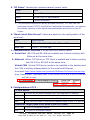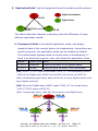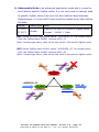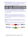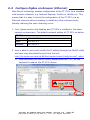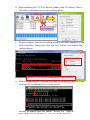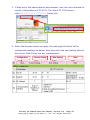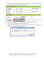
1
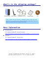
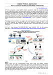
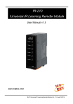
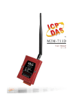
ZT-2570/ZT-2571 User Manual Warranty All products manufactured by ICP DAS are under warranty regarding defective materials for a period of one year, beginning from the date of delivery to the original purchaser. Warning ICP DAS assumes no liability for any damage resulting from the use of this product. ICP DAS reserves the right to change this manual at any time without notice. The information furnished by ICP DAS is believed to be accurate and reliable. However, no responsibility is assumed by ICP DAS for its use, not for any infringements of patents or other rights of third parties resulting from its use. Copyright Copyright © 2012 by ICP DAS. All rights are reserved. Trademark Names are used for identification only and may be registered trademarks of their respective companies. Technology Support If you have any problems, please feel free to contact us via email at [email protected] ICP DAS, ZT‐2570/ZT‐2571 User Manual, Version 1.0 Page 1 Copyright @ 2012 by ICP DAS Co., Ltd. All Rights Reserved. Table of Content 1 Introduction of ZigBee ............................... 4 2 Introduction to the ZT‐257x module ................... 5 3 Hardware Information ................................. 6 3.1 Specifications ................................... 6 3.2 ZT‐257x Front View ............................... 7 3.3 Dimensions (Units: mm) ........................... 8 3.4 Block Diagram .................................... 9 3.5 Wire Connection .................................. 9 4 Setting up the ZT‐257x module ....................... 10 4.1 Introduction of configurations .................. 10 4.2 Connecting the Power and Host PC ................ 16 4.3 Configure ZigBee via Utility (Serial/Ethernet) .. 17 4.4 Configure ZigBee via Browser (Ethernet) ........ 20 4.5 Test Communications ............................. 24 5 Applications ........................................ 26 6 Trouble shooting .................................... 27 7 Appendixes .......................................... 29 ICP DAS, ZT‐2570/ZT‐2571 User Manual, Version 1.0 Page 2 Copyright @ 2012 by ICP DAS Co., Ltd. All Rights Reserved. What’s in the shipping package? The package includes the following items: ZT‐257x Device ANT‐124‐05 CA‐0915 (ZT‐2570) / CA‐0910N (ZT‐2571) Release Note CD If any of these items are missing or damaged, please contact your local distributor for more information. Save the shipping materials and cartons in case you want to ship the module in the future. More Information Documentation: CD: \Napdos\ZigBee\ZT_Series\Document http://ftp.icpdas.com/pub/cd/usbcd/napdos/zigbee/zt_series/document Software: CD: \Napdos\ZigBee\ZT_Series\Utility http://ftp.icpdas.com/pub/cd/usbcd/napdos/zigbee/zt_series/utility ICP DAS, ZT‐2570/ZT‐2571 User Manual, Version 1.0 Page 3 Copyright @ 2012 by ICP DAS Co., Ltd. All Rights Reserved. 1 Introduction of ZigBee ZigBee is a specification for a suite of high level communication protocols using small, low-power digital radios based on an IEEE 802.15.4 standard for personal area networks. ZigBee devices are often used in mesh network form to transmit data over longer distances, passing data through intermediate devices to reach more distant ones. This allows ZigBee networks to be formed ad-hoc, with no centralized control or high-power transmitter/receiver able to reach all of the devices. Any ZigBee device can be tasked with running the network. ZigBee is targeted at applications that require a low data rate, long battery life, and secure networking. ZigBee has a defined rate of 250 kbit/s, best suited for periodic or intermittent data or a single signal transmission from a sensor or input device. Applications include wireless light switches, electrical meters with in-home-displays, traffic management systems, and other consumer and industrial equipment that requires short-range wireless transfer of data at relatively low rates. The technology defined by the ZigBee specification is intended to be simpler and less expensive than other WPANs. ICP DAS, ZT‐2570/ZT‐2571 User Manual, Version 1.0 Page 4 Copyright @ 2012 by ICP DAS Co., Ltd. All Rights Reserved. 2 Introduction to the ZT‐257x module The Basis of ZT-257x Series Product The ZT-2570 and ZT-2571 series modules are small-sized wireless ZigBee converters based on the IEEE802.15.4 standard that allow RS-232, RS-485 and Ethernet interface to be converted to a personal area ZigBee network. The typical transmission of ICP DAS ZT series ZigBee products is 700 meters (LOS, line of sight), with a transmission frequency range of between 2.405 GHz and 2.48 GHz, separated into 5 MHz sectors, providing 16 channels and 16384 PAN IDs. ZT-2000 series is not only a long distance wireless converter but also can act a ZigBee router to extend the transmission range and improve the quality of wireless signal. ZT-2000 series products are specification for a suite of high level communication protocols using small, low-power digital radios module, which are fitted the ZigBee 2007 (ZigBee Pro) of ZigBee Alliance. In the ZigBee network, it is only allowed one ZigBee Host and called “ZigBee Coordinator”, ZT-2570 series products, are used to initialize and manager the routing. In addition, One ZigBee network are able to manager 255 ZigBee router and responsible for receiving or bypassing data from parent or child node. The Benefits of ZT-257x Series Product A Windows compatible GUI configuration utility is available. The utility allows users to set different configurations based on the type of application, together with several of required ZigBee variables such as Pan ID. The friendly user interface is also helping user be familiar with ZT-2000 series. For more information, please refer to the relevant documents for these devices, which can be found at following link: http://ftp.icpdas.com/pub/cd/usbcd/napdos/zigbee/zt_series/document ICP DAS, ZT‐2570/ZT‐2571 User Manual, Version 1.0 Page 5 Copyright @ 2012 by ICP DAS Co., Ltd. All Rights Reserved. 3 Hardware Information 3.1 Specifications Part Number ZT-2570 (ZigBee Coordinator) ZT-2571 (ZigBee Router) Hardware CPU 80186, 80 MHz or compatible Temporary Buffer Size 2300 Bytes LED Green ZigBee Net Yellow ZigBee RxD Red ZigBee Power Communication Interface (COM 0) RS-232 (TxD, RxD and GND); RS232 D-Sub 9 Female, Non-isolated D-Sub 9 Male, Non-isolated RS-485 RS-485 (DATA+, DATA-; internal ASIC self-tuner); Non-isolated Baud Rate 1200 ~ 115200 bps Data Bit 7, 8 Parity Check Even, Odd, None Stop Bit 1, 2 Communication Interface (Ethernet) Ethernet 10/100 Base-TX (Auto-negotiating, auto_MDI/MDI-X, LED indicators) Power Protection Power reverse polarity protection EMS Protection ESD, Surge, EFT Required Supply Voltage +10V DC ~ +30V DC Power Consumption 2.5 W (Max.) Mechanism Casing Plastic Flammability UL 94V-0 materials Dimensions 33 mm x 78 mm x 107 mm (W x L x H) Installation DIN-Rail Environment Operating Temperature -25 °C ~ +75 °C Storage Temperature -40 °C ~ +80 °C Relative Humidity 5 ~ 95% RH (non-condensing) Wireless RF Channel 16 RF Transmit Power 11 dBm Antenna (2.4GHz) 5 dBi Omni-Directional antenna Transmit Range (LOS) 700 m (Typical) Max. Slaves Supported 255 EMC CE/FCC, FCC ID ICP DAS, ZT‐2570/ZT‐2571 User Manual, Version 1.0 Page 6 Copyright @ 2012 by ICP DAS Co., Ltd. All Rights Reserved. 3.2 ZT-257x Front View System LED Indicator 1 6 2.4GHz RP-SMA Antenna 5 RS-232 4 Ethernet UL 94V-0 materials Operating Mode DIP Switch 3 2 +10~+30 VDC Power input and RS-485 1. LED Indicator Status LED Indicator LED Color Explain ZigBee Net Green The status of ZigBee network. ZigBee RxD Yellow The status of ZigBee communication ZigBee PWR Red The status of module board ※ For more details, please see the section 6 troubleshooting. 2. Operating Mode DIP Switch ZBSET:Configuration mode is able to use browser or ZT Configuration Utility to configure via the Ethernet, RS-232 or RS-485 interface. ZBRUN:Transmit mode is used to transmit data to the remote device. ZBINIT:Operating system initial state, it is used to update firmware. 3. RS-485 and +10~+30VDC Power input The RS-485 and RS-232 are communicable via the same UART. The ZigBee PWR indicator will be steady light if correct power input. 4. Ethernet The port RJ-45 jack is the 10/100 Base-TX Ethernet port. 5. RS-232 The RS-485 and RS-232 are communicable via the same UART. 6. 2.4 GHz RP-SMA Omni-directional Antenna If there is any requirement for extension cable, it must be a connector with the type RPSMA and resistance 50 Ohm. Ex. 3S001-1, 3S003-1...etc ICP DAS, ZT‐2570/ZT‐2571 User Manual, Version 1.0 Page 7 Copyright @ 2012 by ICP DAS Co., Ltd. All Rights Reserved. 3.3 Dimensions (Units: mm) Left Side View Front View Top View Rear View Right Side View Bottom View ICP DAS, ZT‐2570/ZT‐2571 User Manual, Version 1.0 Page 8 Copyright @ 2012 by ICP DAS Co., Ltd. All Rights Reserved. 3.4 Block Diagram LED Display Ethernet Interface RS‐232 Interface CPU Self‐Tunes (80186‐80MHz) ZigBee Module RS‐485 Interface EEPROM SRAM FLASH Setting Switch Power Circuit +10 ~ 30VDC 3.5 Wire Connection 1. RS-232 GND ZT‐2570 TxD RxD CA‐0915 ZT‐2571 TxD RxD GND CA‐0910N 2. RS-485 DD+ D+D - ICP DAS, ZT‐2570/ZT‐2571 User Manual, Version 1.0 Page 9 Copyright @ 2012 by ICP DAS Co., Ltd. All Rights Reserved. 4 Setting up the ZT‐257x module 4.1 Introduction of configurations 1. “Pan ID” is the group identity of ZigBee networks. It must be the same if they are in the same ZigBee network. (Valid values range from 0x0000 to 0x3FFF) 2. “Node ID” is the identity of the ZigBee module. The identity number must be unique if it is in the same ZigBee network as other ZigBee module. (Valid values range from 0x0001 to 0xFFF7 for a ZigBee Router, but is fixed to 0x0000 for a ZigBee Coordinator) 3. “RF Channel” indicates the radio frequency channel, and must be set to the same channel if the module is in the same ZigBee network as other ZigBee modules. Channel 0x00 0x01 …… 0x0F Frequency(MHz) 2405 2410 …… 2480 Note: In addition, the RF channels 0x04, 0x09, 0x0E or 0x0F are recommended because they do not overlap with frequencies Wi-Fi. 802.11b/g Channel 1 2400 00 01 02 03 04 MHz 802.11b/g Channel 6 802.11b/g Channel 11 05 06 07 08 09 0A 0B 0C 0D 0E 0F 2485 MHz 802.11b/g Channel (North America) 802.15.4 Channel ICP DAS, ZT‐2570/ZT‐2571 User Manual, Version 1.0 Page 10 Copyright @ 2012 by ICP DAS Co., Ltd. All Rights Reserved. 4. Communication Speed (Broadcasting Frame Sending Interval): The packet payload of ZT-2000 series devices is 79 bytes. Data above 79 bytes will be transmitted in several packets. This parameter decides the broadcasting frame sending interval time to avoid the network overloading. User only fills in the number of ZT-2000 slaves nearby the ZigBee Coordinator. Example: RS-232 200 Bytes RS-485 Ethernet 75ms 42 B 75ms 79 Bytes 79 Bytes RS-232 79 Bytes 79 Bytes 42 B RS-485 Ethernet (Keep relay data) ICP DAS, ZT‐2570/ZT‐2571 User Manual, Version 1.0 Page 11 Copyright @ 2012 by ICP DAS Co., Ltd. All Rights Reserved. 5. “RF Power” denotes the wireless transmit power value. Code Note 0x0F Typical Maximum 0x08 Fit the CE/FCC certification 0x00 Typical Minimum ※ The parameter adjustment purely personal behavior, ICP DAS can not guarantee to pass CE/FCC certification if adjusting this parameter, nor assume any liability because of the adjustment parameters derived from the RF Power. 6. “Baud rate & Data Format” values are based on the configuration of the serial port. Item Specification Data Format N81、O71、E71、N82、O81、E81 or N82 Baud rate 1200 ~ 115200 bps 7. Communication Interface is three types provided as below. a. Serial Port:RS-232 and RS-485 are enabled and it allows working with Ethernet at the same time. b. Ethernet:Either TCP Server or TCP Client is enabled and it allows working with RS-232 or RS-485 at the same time. Virtual COM:Virtual COM driver needs to be installed in the desktop and the COM is working independently to the serial and Ethernet. Download: http://www.icpdas.com/products/Software/VxComm/vxcomm.htm Note: Please select “Fixed baud rate” if the virtual COM is not in the 115200 bps and N81 format. 8. Configurations of TCP: ZT-257x device IP IP must be the same segment with LAN segment of desktop Mask Mask must be the same with LAN of desktop Gateway Gateway must be the same with LAN of desktop Port User port will listen to connection request when it acts TCP Server Connection Target (Need to set when it acts TCP Client) IP The IP of connection target Port The port of connection target ICP DAS, ZT‐2570/ZT‐2571 User Manual, Version 1.0 Page 12 Copyright @ 2012 by ICP DAS Co., Ltd. All Rights Reserved. 9. “Application Mode” can be changed and used for certain specific purpose. ZC ZS 00 00 ZS 00 01 ZC ZigBee Coordinator ZS ZigBee Slave 00 02 The above schematic diagram is showing what the difference of using different application modes. a. Transparent Mode is the default application mode, and always transmits data to the remote device via broadcasting. Unless there are specific purposes, the application mode can be retained as default. The mode always bypasses data to remote side via broadcasting. If there is no particular purpose, user only keeps this application mode. Module Frame Type Note ZT-2570 Broadcast Data will be sent to all ZigBee slaves ZT-2571 Unicast Data will only be sent to the coordinator [Ex1] When ZT-2570 ZigBee Host sends “DATA_01” via broadcasting frame, →Both of the ZigBee slave 0x0001 and 0x0002 will receive the DATA_01. (Note: Broadcasting type frame, data will be sent to every ZigBee slaves in the same ZigBee network) [Ex2] When the ZigBee slave 0x0001 sends “DATA_02” via unicast frame, →Only ZT-2550 receives DATA_02. (Note: Unicast type frame, data will only be sent to the ZigBee host) DATA_03 ZC_0000 DATA_02 Transparent DATA_01 DATA_02 ZS_0001 Transparent DATA_01 ZS_0002 Transparent DATA_03 DATA_01 ICP DAS, ZT‐2570/ZT‐2571 User Manual, Version 1.0 Page 13 Copyright @ 2012 by ICP DAS Co., Ltd. All Rights Reserved. b. Addressable Mode is an advanced application mode and it is used to send data to specific ZigBee nodes. It is not only used to transmit data to specific ZigBee slaves from host but also transmit data between ZigBee slaves. A 5-byte ASCII code should be added as an index before the data. Module ZT-2570 ZT-2571 Frame Type Note Data will be sent to a specific ZigBee slave. Unicast Format: “:AAAA” + Data [EX1] When ZT-2570 ZigBee Host sends “:0001DATA_01” via unicast frame, →Only the ZigBee Slave 0x0001 receives DATA_01. (Note: Unicast type frame, data will be only sent to the specific ZigBee node) [EX2] When ZigBee slave 0x0001 sends “:0002DATA_02” via unicast frame, →Only the ZigBee Slave 0x0002 receives DATA_02. (Note: Unicast type frame, data will be only sent to the specific ZigBee node) DATA_03 :0001DATA_01 DATA_04 ZC_0000 Addressable :0002DATA_02 ZS_0001 Addressable DATA_01 DATA_04 DATA_02 ZS_0002 Transparent DATA_03 ICP DAS, ZT‐2570/ZT‐2571 User Manual, Version 1.0 Page 14 Copyright @ 2012 by ICP DAS Co., Ltd. All Rights Reserved. a. Modbus Gateway Mode is an advanced application mode and it is used to convert the Modbus protocol.Data is regarded as Modbus RTU if communicates through via RS-232 or RS-485, else data is regarded as Modbus TCP if it communicates via the Ethernet. Module Frame Type Note ZT-2570 Broadcast Data will be sent to all ZigBee slaves ZT-2571 Unicast Data will only be sent to the coordinator [EX1] When ZT-2570 receives data “MRTU_CMD_01” from serial port, →ZT-2571 will output the data “MRTU_CMD_01” directly to serial port. →ZT-2571 will convert protocol then output “MTCP_CMD_01” to Ethernet. (Note: Broadcasting type frame, data will be sent to every ZigBee slaves in the same ZigBee network) [EX2] When ZT-2570 receives data “MTCP_CMD_02” from Ethernet, →ZT-2571 will convert protocol then output “MRTU_CMD_01” to serial port. →ZT-2571 will output the data “MTCP_CMD_01” directly to Ethernet. (Note: Broadcasting type frame, data will be sent to every ZigBee slaves in the same ZigBee network) [EX3] When ZT-2571 transmits the acknowledgement “MRTU_ACK_03”, →ZT-2570 will response the acknowledgement “MRTU_ACK_03” directly to serial port. →ZT-2570 will convert protocol then output “MTCP_CMD_01” to Ethernet. (Note: Unicast type frame, data will only be sent to the ZigBee host) MODBUS RTU Serial MODBUS TCP Ethernet ZC_0000 ZS_0001 Ethernet MODBUS TCP Serial MODBUS RTU ICP DAS, ZT‐2570/ZT‐2571 User Manual, Version 1.0 Page 15 Copyright @ 2012 by ICP DAS Co., Ltd. All Rights Reserved. 4.2 Connecting the Power and Host PC 1. Confirm that the DIP switch is set to the “ZBSET” position. ZBSET/ZBRUN/ZBINIT 2. Connect RS-232, RS-485 or Ethernet interface to configure the ZT-257x. RS-232: ZT‐2570: CA‐0915 ZT‐2571: CA‐0910N Windows Based PC RS-485: F.G. D‐ D+ GND +VS ZT‐255x RS‐485 Converter Windows Based PC Ethernet: ZT‐2570/ZB‐2571: Windows Based PC 3. Enable the power. It means that the ZT-257x start-up procedure has been completed. If the red LED has changed from blinking to a steady light. ICP DAS, ZT‐2570/ZT‐2571 User Manual, Version 1.0 Page 16 Copyright @ 2012 by ICP DAS Co., Ltd. All Rights Reserved. 4.3 Configure ZigBee via Utility (Serial/Ethernet) 1. Launch the software “ZT Configuration Utility” and select the [ZT Series]. 2. Click the either [Serial Port] or [Ethernet] icon and then select the correct COM Port number or IP address. Serial Port 1 Ethernet 2 ICP DAS, ZT‐2570/ZT‐2571 User Manual, Version 1.0 Page 17 Copyright @ 2012 by ICP DAS Co., Ltd. All Rights Reserved. 3. After selecting the COM Port number, a list of model numbers will be displayed. Select the name of the module that you want to configure. After clicking the button, the utility will begin checking the connection. 3 4. Once a connection is established, select either the [Default] or the [Wizard] function from the settings mode page. 設定精靈 Default 5. Whether you select either the [Default] or the [Wizard] option for performing configuration, both are used to configure the Pan ID, Node ID, RF Channel, RF Power, Baud rate, Data Format, Application Mode and so the relevant parameters. ICP DAS, ZT‐2570/ZT‐2571 User Manual, Version 1.0 Page 18 Copyright @ 2012 by ICP DAS Co., Ltd. All Rights Reserved. 6. Once the module configuration has been completed, the message “The Configuration was successful” will be displayed. Return the DIP switch to the “ZBRUN” position and reboot the ZT-255x device. ICP DAS, ZT‐2570/ZT‐2571 User Manual, Version 1.0 Page 19 Copyright @ 2012 by ICP DAS Co., Ltd. All Rights Reserved. 4.4 Configure ZigBee via Browser (Ethernet) Web Server technology enables configuration of the ZT-257x via a standard web browser interface, e.g. Internet Explorer, FireFox or Mozilla, etc. This means that it is easy to check the configuration of the ZT-257x via an Ethernet network without needing to install any other software tools, thereby reducing the userʼs learning curve. 1. First, please confirm the desktop and ZT-257x is installed in the same network environment. The default network setting of ZT-257x as below. ZT-257x device IP 192.168.255.1 Mask 255.255.0.0 Gateway 192.168.0.1 2. User is able to query and modify the IP setting through via MiniOS utility and user may download the tool from the link: http://ftp.icpdas.com/pub/cd/8000cd/napdos/minios7/utility/minios7_utility/ a. After launching the MiniOS utility, please press the “F12” on the keyboard to search the ZT-257x device. ICP DAS, ZT‐2570/ZT‐2571 User Manual, Version 1.0 Page 20 Copyright @ 2012 by ICP DAS Co., Ltd. All Rights Reserved. b. After selecting the ZT-257x device, please click “IP setting” then it will show a windows form to do configuration. c. Please configure the new IP setting which is the same segment to the LAN of desktop. Please also click the “Set” button to complete the configurations. Set the ZT-257x to the same network environment d. After configuring the IP setting, you may try to ping the device to see whether the configuration is correct or not. ICP DAS, ZT‐2570/ZT‐2571 User Manual, Version 1.0 Page 21 Copyright @ 2012 by ICP DAS Co., Ltd. All Rights Reserved. 3. If they are in the same network environment, user can use a browser to set the configurations of ZT-257x. The site of ZT-257x device: http://○○○.○○○.○○○.○○○/index.htm 4. When the browser access correctly, the web page will show all the configuration settings as below. User may enter the new setting value to the correct filed if there are any requirements. Configuration Current Setting New Setting Note ICP DAS, ZT‐2570/ZT‐2571 User Manual, Version 1.0 Page 22 Copyright @ 2012 by ICP DAS Co., Ltd. All Rights Reserved. 5. If the new configuration is completed, please click “Update New Config” button to start the ZT-257x configuration. 6. When the configuration completed and successful, it will show … “The system is updated with new configurations!” “Please reload the web page to see whether the configuration is correct or not” then user may follow this instructions. ICP DAS, ZT‐2570/ZT‐2571 User Manual, Version 1.0 Page 23 Copyright @ 2012 by ICP DAS Co., Ltd. All Rights Reserved. 4.5 Test Communications When all the configuration set-up completed, please turn the DIP switch to “ZBRUN” position and reboot module. ZBSET/ZBRUN/ZBINIT Next, please confirm the “ZB Net” LED indicator of ZigBee salves whether is steady lighted or not. If the status of green LED indicator is steady lighted, it means the connection has established and user can start using Ethernet or serial port to do communication. ZB Net ZB PWR A. Serial Port Test Method (1) Connect both the ZT-2570 and ZT-2571 to the Host PC via the RS-232 port. You may need to use two serial port tools to simulate the data transmission. Serial Tool RS‐232/RS‐485 ZT‐2570 Serial Tool RS‐232/RS‐485 ZT‐2571 ICP DAS, ZT‐2570/ZT‐2571 User Manual, Version 1.0 Page 24 Copyright @ 2012 by ICP DAS Co., Ltd. All Rights Reserved. Method (2): Use the DCON Utility on the Host PC to search for ZT-2000 series I/O modules. If there any devices are found, it means that the configuration is correct. DCON Utility RS‐232/RS‐485 ZT‐2570 ZT‐2000 ※ Download MiniOS Utility: http://ftp.icpdas.com/pub/cd/8000cd/napdos/minios7/utility/minios7_utility/ ※ If there is not any serial tool can be used, please use “Send232.exe” which is a serial tool at the directory:\ICPDAS\MiniOS7_Utility\bin\Send232.exe B. Ethernet Test Method(1): Connect both the ZT-2570 and ZT-2571 to the Host PC via the Ethernet port. You may need to use two TCP Server/Client tools to simulate the data transmission. Method(2): Use the EZ-Data Logger as a TCP Client which is connected to the ZT-2570 on the Host PC to search for ZT-2000 series I/O modules. If there any devices are found, it means that the configuration is correct. EZ Data Logger Ethernet ZT‐2570 ZT‐2000 ICP DAS, ZT‐2570/ZT‐2571 User Manual, Version 1.0 Page 25 Copyright @ 2012 by ICP DAS Co., Ltd. All Rights Reserved. 5 Applications (1)ZT-257x is suitable for using in which is wiring difficult and low data rate environment. Ex. The I/O nodes are across the road, building or gutter… Factory 01 Factory 03 ZT‐2000 I/O Ethernet Serial ZT‐2570 ET‐7000 / MTCP device ZT‐2571 Road ZT‐2000 I/O ZT‐2551 ZT‐2000 I/O Factory 02 RS‐485 Gutter M‐7000/MRTU device (2)ZT-255x is suitable to use in monitoring and controlling. Ex. Smart energy, Home automation... Light Control Thermostat Audio Control Window treatment Security ICP DAS, ZT‐2570/ZT‐2571 User Manual, Version 1.0 Page 26 Copyright @ 2012 by ICP DAS Co., Ltd. All Rights Reserved. 6 Trouble shooting (1) Technical Support. If you are any difficulties using the ZT-255x module, save the ZigBee configurations using the described below. Please also provide a description of problem and attach file to an email and send it to [email protected] 1. Set the DIP switch of the ZT-255x device to the [ZBSET] position then reboot the device. Launch the ZT Configuration Utility and select [Save Log] icon to save the configuration of ZT-255x as a file. 2. After clicking the [Save Log] icon, enter the “File Name” and “File Path” in the Windows save dialog. Once the configuration has been successfully saved, the following message will be displayed. ICP DAS, ZT‐2570/ZT‐2571 User Manual, Version 1.0 Page 27 Copyright @ 2012 by ICP DAS Co., Ltd. All Rights Reserved. (2) LED Indicator Status: LED Indicator Status Introduction The status of ZigBee network [ZigBee Coordinator (Host)] Steady Lit ZigBee network is establish Blink to Steady Lit Rejoin ZigBee network or it has occupied ZigBee Net The status of ZigBee network [ZigBee Router (Slave)] (Green LED) Steady Lit Signal Strength Blinking (500 ms) Signal Available Blinking (1s) Signal Weak Blinking (2s) Signal Terrible or No ZigBee Network ZigBee RxD (Yellow LED) The status of ZigBee communication Blinking Receiving ZigBee data Steady Unlit No ZigBee data received The status of module board ZigBee PWR (Red LED) Steady Lit Power on Blinking (200ms) Module Initialization failure Blinking (1s) Watchdog enabled Steady Unlit Power off ICP DAS, ZT‐2570/ZT‐2571 User Manual, Version 1.0 Page 28 Copyright @ 2012 by ICP DAS Co., Ltd. All Rights Reserved. 7 Appendixes Technology Support If there is any question or concern for using ZT-2000 series module, please feel free to contact us. ICP DAS will reply you within three days at most as possible as we can. Taiwan Europe Website:http://www.icpads.com Website:http://www.icpdas-europe.com E-Mail:[email protected] E-mail:[email protected] TEL:886-3-597-3366 TEL:+49(0) 7121-143324-0 FAX:886-3-597-3733 FAX:+49(0) 7121-14324-90 China USA Website:http://www.icpdas.com.cn Website:http://www.icpdas-usa.com E-Mail:[email protected] E-Mail:mailto:[email protected] TEL:86-21-6247-1722 TEL:1-310-517-9888 x101 FAX:86-21-6247-1725 FAX:1-310-517-0998 ICP DAS, ZT‐2570/ZT‐2571 User Manual, Version 1.0 Page 29 Copyright @ 2012 by ICP DAS Co., Ltd. All Rights Reserved.