1
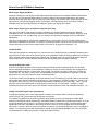
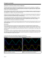
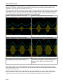
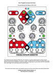
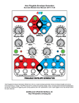
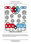
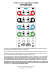
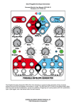
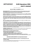
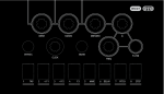
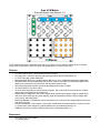
4ms VCA Matrix
Eurorack Module User Manual v1.0
The VCA Matrix from 4ms is a playable 4x4 matrix of 16 VCAs. The four audio/CV inputs can be routed and
mixed in any combination to the four outputs, with independent CV control of each VCA.
Features
•
•
•
•
•
•
•
•
•
•
•
•
•
4 CV/audio inputs and 4 outputs (buffered and dc-coupled)
Full range (0Hz - 20kHz) for both Control and Signal inputs, allows for AM effects, etc.
16 VCA's using high quality SSM chips
Attenuation/gain range from -100dB (mute) to 0dB (unity). Up to +20dB boost with trimpot adjustment.
Playable surface with 16 latching Mute LED buttons, used to mute each VCA individually (Mute button
disconnects Control jack and Level knob, and fully attenuates the VCA)
LED button brightness indicates amount of attenuation and Control CV signal
16 Control jacks for VCA level control
16 Level knobs attenuate the incoming Control signals. The Level knobs act as manual level controls
when nothing is plugged into the Control jack
Exponential VCA response in low control voltage range, pseudo-log response in higher voltage range.
"Soft Limit" effect limits gain to prevent clipping, while still responding to higher Control voltages with
more "punch" and wider pulses
Matrix Expandability: VCA Matrices can be connected to form a larger matrix using headers on the back
(4x8, 8x8, 12x4, etc)
Control Expandability: 16-pin header on back side of PCB allows an external device to control all VCAs:
e.g. patch recall, patch sequencing, preset patterns such as quadrature panning, etc.
Suitable as a 4x4 mixer, splitter, dynamic signal router, limited waveshaper, etc.
Dimensions
•
•
26 HP Eurorack format module
1.6” (40mm) deep
How to Use the VCA Matrix: Examples
Basic usage: Simple 4x4 Mixer
Simply by running up to four inputs into the Signal Inputs and running the four outputs to different destinations,
you can use the Level pots and Mute buttons to route the inputs in any amount/combination to the outputs.
Although seemingly trivial, this is often a good way to start using the VCA Matrix while creating a patch. As your
patch evolves, you will start plugging into the Control jacks, mult'ing/stacking inputs and outputs, creating
feedback loops, and generally using the VCA Matrix to weave your signals into a patch.
Basic usage: Keeping your modulations related to each other
Let's say you're making a patch and you want to modulate four different parameters using four different
modulation sources. You want all the modulations to be related to each other but not identical. Simply by using
the VCA Matrix as a 4-in, 4-output mixer, you can quickly have synchronicity between your four modulation
destinations.
Now take it a step farther by running other modulations (e.g. touch pads, LFOs, etc) into the Control jacks to
control each modulation mix amount. For instance, run the four pressure outputs of of a Pressure Points into four
Control jacks and you have a touch surface mixer. Or use the PP to trigger four envelopes... etc.
Feedback Mixer
Taking the last example one step further, you can take one of the outputs (mult'ing or stacked if necessary) and
plug that back to one or more of the Control inputs on the VCA Matrix. Continue routing outputs back into Control
inputs, perhaps running them through other modules first. Feedback loops can quickly spiral exponentially into
chaos or flat-lined CV, so using the Mute buttons and carefully setting the Level pots is essential.
Amplitude Modulation (AM)
Since the VCA Matrix operates in the full audio range for both the Control and Signal inputs, you can easily
achieve Amplitude Modulation (“cross modulation”) effects by running an audio frequency into the Signal input
and another audio signal into a Control input. For example, run VCO #1 into Input A. Now run a VCO #2 into
Control input A-1. On output 1 you'll hear a rich sound based on both input frequencies. Adjust the VCOs and
play with the A-1 Level pot to hear the range of textures possible.
Tip: Run the Control VCO #2 through an unused channel on the VCA Matrix (e.g. Input B), and run an envelope
with a sharp attack into the associated control jack (e.g. Control input B-2). Patch the output (e.g. Output 2) into
the original Control Input (e.g. A-1). Now the AM effect will be modulated in a percussive way.... and.... you can
play with various associations such as bringing some of the Control VCO into Output 1 (using B-1). Keep
extending this patch in the same way to have another VCO#3 modulate VCO#2, with a different envelope... etc.
Voltage Controlled Signal router (Quadrature)
In quadrature panning, one or more input signals is routed to four outputs (which could be four speakers),
usually using 4 LFO CVs that are each 90 degrees out of phase.
For example, the MATHS can be used to generate quasi-quadrature LFOs, by following the “Whirly Bird”
example in the MATHS manual. Alternatively, the Malekko/Wiard Oscillator has a variable phase output, so it can
be used to generate two 90-degree out-of-phase triangle waves. From either module, mult/stack both triangle
signals and invert them, and then run the inversions into A-3 and A-4. Run the original non-inverted triangle
waves into A-1 and A-2. With the Level pots on Row A turned up, you should see the lights swell in a quadrature
fashion. You may wish to level-shift the Oscillator's outputs using the Malekko 8NU8R's “red” mode, a MATHS,
the Bubblesound LvL+RM or any number of other level shifter modules.
Page 2
Examples (continued)
Hybrid Patch: 1V/Oct VCO controller and Cross Modulator
This patch requires three VCOs with 1V/oct inputs and one CV source (e.g. from a sequencer, a keyboard, or
perhaps random stepped voltages). Part of the VCA Matrix is used for 1V/oct routing and part is used for audio
mixing. The rest of the matrix allows for feedback-loops/cross modulation. The patch may seem complicated to
grasp at first, so we'll build it step-by-step:
Start by Muting everything. Patch the three VCO outputs into the VCA Matrix Inputs B, C, and D. Run output 4 to
your output mixer. Unmute B-4, C-4, and D-4 and you can now mix the three VCO audio outputs by using the
Level pots B-4, C-4, and D-4. Tune your VCOs if you want.
Patch the CV source into Input A. Run Outputs 1, 2, and 3 into the 1V/oct inputs of the three VCOs. Unmute A-1,
A-2, and A-3 and fine-tune the pitches with the Level pots A-1, A-2, and A-3 so that the oscillators sound good
together. See section on Precision Tuning for more information.
Here's where it gets interesting... By unmuting one of the 9 buttons on rows B, C or D and columns 1, 2, or 3,
you will be feeding one of the VCO outputs back into the 1V/oct of another VCO. The result is a web of VCOs
cross modulating each other. The Level pot fine-tunes the effect. Play the Mute buttons, and try running
envelopes into the Control jacks to add motion to the timbres.
Another variation is to use two CV sources into Inputs A and B, and only two VCOs into Inputs C and D. You can
use the Mute buttons and Level knobs to play between the two CV sources and independently setting the level
sent to each VCO.
Waveshaper
Most exponential VCA's can convert a linear control voltage into an exponential signal. This patch simply
involves running a linear waveshape (e.g. a triangle wave) into a Control jack on the VCA Matrix, and running a
constant DC voltage into the Signal jack. The constant DC voltage controls the amplitude of the output. To start,
keep the amplitude of the triangle wave attenuated (around 3V) and use a uni-polar (positive only) triangle wave.
See Figure 1.
The VCA Matrix can also use its pseudo-log response at the upper range of Control voltages to convert a linear
waveshape into a sine wave approximation. Use the same patch as above, but bring the DC-offset of the triangle
wave up so that it starts to soft-limit the VCA Matrix. Adjust the amplitude of the triangle wave as well (you can
use the VCA Matrix's Level pot). See Figure 2.
Control jack signal is top wave (triangle). Output jack is bottom wave.
Steady DC is run into Input jack (not shown). Middle plot is FFT analysis of output.
FIGURE 1:
FIGURE 2:
Triangle to exponential conversion using exponential
portion of VCA Matrix's response
Page 3
Triangle to near-sine conversion using the VCA
Matrix's soft limiting pseudo-log response
Decibel Range
The VCA Matrix can attenuate a maximum of -100dB, when using the Mute button or applying a negative CV.
The maximum gain is factory-set to just over 0dB (unity). Clipping will not occur except in signals with very little
headroom. If you desire clipping, a simple solution is to boost the signal after the VCA Matrix, or adjust the trim
pots (see Trim Pot section). By applying 0V to the Control jack, or by turning the Control knob all the way down,
about -54dB of attenuation results (the LED will be dim, but not off). This is adequate to kill a signal in many
situations, but to achieve maximum attenuation, the Mute button should be pressed off (the LED will go
completely off). Another way to get maximum attenuation is to apply a CV less than -2.75V.
Applied Voltage on Control Jack
(assuming Level pot is all the way up)
Resulting Gain in dB
Resulting Voltage Gain
Muted with button, or <2.75V
-100dB
1 / 100000 (0.00001)
-1V
-74dB
1 / 5000 (0.0002)
0V (pot all the way down)
-54dB
1 / 500 (0.002)
1V
-34dB
1 / 50 (0.02)
4.4V
0dB (unity)
1.00 (unity)
5.0V
About +1dB
1.12
Soft Limit effect
You can think of Soft Limiting as an effect that provides more “punch” when you turn the VCA Matrix up to “11”,
without clipping the signal. The Soft Limit effect is due to a “knee” in the CV/gain curve at around 4V of Control
voltage. When there's less than about 4V of CV applied (after being attenuated by the Level pot), the voltage
gain of the VCA is related exponentially to the control voltage. When more than about 4V of Control voltage is
applied (after the Level pot), the gain starts to increase less rapidly. Knowing how to use the Level pot to
attenuate incoming CV is important to getting the most from your VCA Matrix.
There are many VCA modules that allow the gain to increase untethered as the control signal increases, which is
useful but can result in unwanted clipping and sometimes increased bleed-through and cross-talk. There are
also many VCAs that hard-limit the gain at unity, thus preventing these problems, but at the expense of being
less responsive when overdriven by the control signal.
The VCA Matrix takes a third approach, by creating a soft limit for the gain. The gain is limited so that it won't clip
and has very little bleed-through/cross-talk. As the control signal increases past the knee, the gain continues to
increase by smaller and smaller amounts, in a logarithmic curve. What this sounds like to your ears is that as
you turn the CV up past the soft limit, the output pulses get longer and longer and a little more “punchy”
(assuming you are running an LFO or envelope into the Control jack)
FIGURE 3:
FIGURE 4:
Control Voltage vs Gain (Voltage)
Control Voltage vs. Gain (dB)
10
0
1
-10
0.8
0.6
Gain (dB)
Voltage Gain (Vout/Vin)
1.2
Soft Limiting
0.4
Soft Limiting
-30
-40
0.2
-50
-60
0
0
Page 4
-20
1
2
3
4
Control Voltage
5
6
7
0
1
2
3
4
Control Voltage
5
6
7
Soft Limit Effect (con't)
In the following figures, the Input signal is a 7.6V amplitude sine wave. The Control signal is a triangle wave (top
waveform). The Output is shown in the bottom waveform. The four scope shots show what happens as the
amplitude of the control signal is increased from 3V to 7V.
Notice how output signal gets louder from the first image to the second image as the amplitude of control voltage
is increased from 3V to 4.5V. Then as the control voltage is increased past 4.5V, output only gets a small amount
louder, but the width of the output pulses get longer (less quiet space between pulses). The rounded shape of
the output envelope creates a perceived "punchiness" to the output pulses.
FIGURE 5: Applying 3V amplitude control signal.
FIGURE 6: Applying 4V amplitude control signal
FIGURE 7: Applying 5V amplitude control signal
FIGURE 8: Applying 7V amplitude control signal
5V amplitude control signal results in longer pulses
with only slightly more gain (7.60V vs 8.16V)
7V amplitude control signal results in slightly more
gain, and very long pulses. The envelope of the output
pulse is rounded, which sounds fuller and more
“punchy”
As discussed in the Trim Pot section, the Max Gain trim pot can change the voltage at which the VCA Matrix
begins the logarithmic curve, thus changing not only the maximum gain, but also the applied voltage necessary
to create the Soft Limit effect.
Besides creating the Soft Limit effect, the logarithmic end of the CV/gain curve also is useful in several other
ways. As discussed in other parts of the manual, this log response allows for precision voltage tuning (where
small amounts of boost/cut are necessary), and for waveshaping capabilities (e.g. triangle to sine).
Page 5
Jumpers and settings
Power
Apply standard eurorack format
power (16-pin) to this header. The
red stripe should go down,
matching the white line and “-12V”
lettering on the VCA Matrix circuit
board.
5V Source Select
If your powersupply/case does
not supply 5V, put the blue jumper
across the center pin and right pin
(marked “12V”). This will use the
+12V rail and the VCA Matrix's
internal 5V regulator.
If your powersupply/case does
supply 5V, put the blue jumper
across the center pin and the left
pin (marked “5V”). This will use
the +5V rail from your case for the
VCA Matrix's 5V needs.
Daisychain Inputs
This header is used for creating a
matrix of VCA Matrices. An 8-pin
cable is required and can be
obtained from 4ms (contact us from our website 4mspedals.com). Connecting two VCA Matrices with this header
is the same as stacking/multing the input jacks. This creates a 4-input, 8-output matrix. The inputs on either
module can be used, and they will be routed to either/both modules' output jacks. Further expansion is possible
beyond 4x8 by using another special cable (8-pin, 3 connectors).
Daisychain Outputs
This header is used for creating a matrix of VCA Matrices. Connecting two VCA Matrices with this header will
create an 8-input, 4-output matrix. This is not the same as stacking/multing the output jacks. Only one VCA
Matrix in the chain can have the Output Enable jumpers in place (master). The Output Enable jumpers on the
other VCA Matrix should be removed, so that the output jacks on the slave unit are disabled. Further expansion
beyond 8x4 is possible using a special cable (8-pin, 3 connectors).
CV Expansion
This header allows for connection to an external device that sends CV information to control the 16 VCAs. The
VCA Matrix has a factory-installed ribbon cable connected to the header. Keep the ribbon cable in place unless
you are following instructions from an external device designed to control the VCA Matrix.
The switch pin on each Control jack is connected to a pin on this header. The ribbon cable normalizes the control
jacks to 4.5V. Replacing this constant 4.5V with a variable CV generated by an external module is the basis of
remote-controlled patch storage and recall. External control can always be overridden by patching something
into the Control jack, or by muting the channel. The external CV can also be attenuated with the Level pot. So
even if there is an external brain module controlling the VCA Matrix, you still have full control.
Page 6
Trim pots
There are two trim pots on the VCA Matrix: “Max Gain” and “Offset”. These are factory calibrated, and are not
meant to be adjusted unless you have a specific reason to. Always measure and record the voltage on the wiper
(center) pin of the trim pot before turning it. Their effect on the circuit interrelates, so usually both must be
adjusted whenever one is adjusted. Approximately +/-5mV of precision is required when setting the trim pots.
Max Gain trim pot: This sets the Soft Limit (see section above). Factory setting is around 500mV, before final
calibration. The voltage provides a biasing for Schottky diodes acting at their threshold of reverse/forward
biasing when the incoming CV approaches the soft limit. Changing this trim pot will change the maximum
amount of gain, that is, the point at which the soft limit effect begins to take place. Lower voltages result in more
gain. If set to zero, clipping is possible with extremely hot signals.
Offset trim pot: This effectively sets the amount of attenuation when the pot is turned down or 0V is applied to
the Control jack. This trim pot also alters the response of the soft limit effect, so it's recommended to adjust it
before adjusting the Max Gain trim pot. As you turn this trim pot, the brightness of the LEDs will change when the
pot is turned down. The factory setting is roughly 1.75V, which makes the LEDs dim (but not off) when the pot is
turned all the way down. This provides about -55dB of attenuation. By adjusting this trim pot, you could have a
different amount of attenuation with the pot turned down, and the LED will likewise change in brightness.
Precision tuning (1V/oct, etc)
Due to the logarithmic curve at Control voltages greater than 4V, the pots on the VCA Matrix exhibit high
precision at their upper end (approximately from 4 o'clock to full-up). This is useful if you are running 1V/oct into
the VCA Matrix and then into tuned oscillators because you can precisely tune or de-tune them by adjusting the
pot within this upper range. For example you could run a 1V/oct signal into Input A, and then run Outputs 1 and 2
into two tuned VCOs. By turning both pots up (A-1 and A-2), and then bringing one of the pots slightly down, you
have excellent control over a classic fat detuned VCO sound.
Power consumption
+12V rail:
80mA max with 5V Source jumper selecting external 5V (“5V”)
110mA max with 5V Source jumper selecting internal 5V (“12V”)
+5V rail:
40mA max with 5V Source jumper selecting external 5V (“5V”)
not used with 5V Source jumper selecting internal 5V (“12V”)
-12V rail:
110mA max
Page 7
Quick Start Guide
SIGNAL INPUTS (4)
Patch in four audio and/or CV signals
that you want to mix, attenuate, and/or
route.
Examples:
- Four VCOs/voices
- Four clock signals
- Four LFO/envelopes
- Any combination of any type of signal
that you want to mix in different proportions (dynamically or manually) into four
other things
SIGNAL OUTPUTS (4)
Each of these outputs is a mix of the four inputs.
For example, the amount of Input B’s signal that
appears on Output 3 is set by the yellow circled
Control jack, Level pot, and Mute button (row B,
col 3).
The signal on the jack is attenuated by its Level pot.
Applying 0V on the Control jack
yields approx -55dB of attenuation. (Less than 0V can yield up to
-100dB of attenuation)
Applying 5V on the Control jack
yields a slight amount of gain
(less than +1dB typically-- see the
section on 1V/oct tuning for the
usefulness). Unity gain is at 4.6V.
More than 5V can produce up to
+10dB gain, see the section on
“Soft Limiting”.
LEVEL POTS (16)
Each pot controls the attenuation of the
corresponding VCA, or attenuates the
incoming Control CV.
MUTE BUTTONS
with LED INDICATORS (16)
Each button in the matrix mutes
the corresponding VCA.
Muting overrides any Control
input or Level pot setting.
If nothing is plugged into the corresponding Control jack, then the Level pot acts
as a level control. The LED will change
in brightness as you turn the pot.
When something is plugged into the
Control jack, the Level pot acts as an
attenuator for that control signal.
Note: When the Level pot is all the way
down, about -55dB of attenuation is
provided. The LED will be dim, but not
off (this is useful for determining if a
channel is Muted or just turned down).
Muting the channel will turn the LED
completely off and provide about -100dB
of attenuation.
CONTROL JACKS (16)
Each jack allows CV control of the
corresponding VCA.
The LED brightness indicates the
gain of the VCA.
for more information: http://4mspedals.com/vcam.php
For example, pressing the yellow
circled button will mute Input B
from Output 3 (-100dB of attenuation). The LED will go off. Pressing
the button again will allow the
Level pot and Control jack to
determine the amount of Input B
that appears on Output 3.