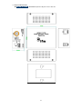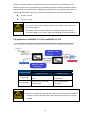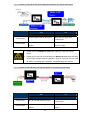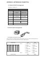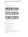
1
IFS MC252-1T-1CXP and MC252-1P-1CX User Manual P/N 1072682 • REV B • ISS 13NOV14 Copyright Trademarks and patents © 2014 United Technologies Corporation Interlogix is part of UTC Building & Industrial Systems, a unit of United Technologies Corporation. All rights reserved. The IFS MC252-1T-1CXP and MC252-1P-1CX name and logo are trademarks of United Technologies. Other trade names used in this document may be trademarks or registered trademarks of the manufacturers or vendors of the respective products. Manufacturer UTC Building & Industrial Systems, Inc. 2955 Red Hill Avenue Costa Mesa, CA 92626-5923, USA Authorized EU manufacturing representative: UTC Climate Controls & Security B.V., Kelvinstraat 7, 6003 DH Weert, Netherlands Intended use Use this product only for the purpose it was designed for; refer to the data sheet and user documentation for details. For the latest product information, contact your local supplier or visit us online at www.interlogix.com. Certification N4131 FCC compliance This equipment has been tested and found to comply with the limits for a Class A digital device, pursuant to part 15 of the FCC Rules. These limits are designed to provide reasonable protection against harmful interference when the equipment is operated in a commercial environment. This equipment generates, uses, and can radiate radio frequency energy and, if not installed and used in accordance with the instruction manual, may cause harmful interference to radio communications. You are cautioned that any changes or modifications not expressly approved by the party responsible for compliance could void the user's authority to operate the equipment. ACMA compliance Notice! This is a Class A product. In a domestic environment this product may cause radio interference in which case the user may be required to take adequate measures. Canada This Class A digital apparatus complies with Canadian ICES-003. Cet appareil numérique de la classe A est conforme á la norme NMB-003du Canada. European Union directives 2004/108/EC (EMC Directive): Hereby, UTC Building & Information Systems, Inc. declares that this device is in compliance with the essential requirements and other relevant provisions of Directive 2004/108/EC. Contact Information For contact information, see www.interlogix.com or www.utcfssecurityproducts.eu. 2 TABLE OF CONTENTS IFS MC252-1T-1CXP AND MC252-1P-1CX USER MANUAL ................................................. 1 1. INTRODUCTION ................................................................................................................... 4 1.1 PACKAGE CONTENTS ...........................................................................................................................4 1.2 PRODUCT FEATURES ...........................................................................................................................5 1.3 PRODUCT SPECIFICATIONS ..................................................................................................................6 2. INSTALLATION .................................................................................................................. 10 2.1 PRODUCT DESCRIPTION .....................................................................................................................10 2.1.1 Power over Coaxial Extender Front Panel...................................................................................11 2.1.2 LED Indicators ............................................................................................................................11 2.1.3 Power over Coaxial Extender Rear Panel....................................................................................12 2.2 APPLICATIONS OF MC252-1T-1CXP AND MC252-1P-1CX .............................................................13 3. TROUBLESHOOTING ........................................................................................................ 16 APPENDIX A: NETWORKING CONNECTION ...................................................................... 17 A.1 SWITCH’S RJ-45 PIN ASSIGNMENTS .................................................................................................17 A.2 RJ-45 CABLE PIN ASSIGNMENTS ......................................................................................................17 APPENDIX B: COAXIAL CABLE LOSS REFERENCES ...................................................... 19 B.1 RG-6/U.............................................................................................................................................19 B.1.1 Physical Characteristics (Overall)...............................................................................................19 B.1.2 Electrical Characteristics (Overall) .............................................................................................19 B.2 RG-59/U...........................................................................................................................................20 B.2.1 Physical Characteristics (Overall)...............................................................................................20 B.2.2 Electrical Characteristics (Overall) .............................................................................................21 3 1. INTRODUCTION Thank you for purchasing IFS Industrial Power over Coaxial Extender, MC252-1T-1CXP and MC252-1P-1CX. The descriptions of the two models are as follows: MC252-1T-1CXP MC252-1P-1CX PoE over Coaxial Extender - Transmitter (1-Port 10/100TX 802.3at PoE PD + 1-Port BNC PoE ) PoE over Coaxial Extender - Receiver (1-Port 10/100TX 802.3at PoE PSE + 12/24V DC Splitter) “Industrial Power over Coaxial Extender” mentioned in this Manual represents the above two models. 1.1 Package Contents Open the box of the Industrial Power over Coaxial Extender and carefully unpack it. The box should contain the following items: For MC252-1T-1CXP ● Industrial Power over Coaxial For MC252-1P-1CX ● Extender – Transmitter x 1 ● User's Manual x 1 ● Power Adapter and Power Cord Industrial Power over Coaxial Extender –Receiver x 1 ● User's Manual x 1 If any of these are missing or damaged, please contact your dealer immediately; if possible, retain the carton including the original packing material, and use them again to repack the product in case there is a need to return it to us for repair. 4 1.2 Product Features Physical Port Ports Model Name Copper BNC MC252-1T-1CXP 1 x 10/100Base-TX (PoE IN) Power/Data Transmitter MC252-1P-1CX 1 x 10/100Base-TX (PoE OUT) Power/Data Receiver Power over Ethernet Eliminates Power cabling with PoE over Coaxial Ethernet over coaxial up to 1km with RG59U/RG6 75 Ohm Low Loss cable Complies with IEEE 802.3af / IEEE 802.3at Power over Ethernet on RJ-45 ports Supports PoE Power up to 30.8 watts (Vary on Power Source and Coaxial Distance) Auto detect powered device (PD) (MC252-1P-1CX) Layer 2 Features Supports Auto-negotiation and 10/100Mbps half / full duplex and 1000Mbps full duplex mode Prevents packet loss with back pressure (Half-Duplex) and IEEE 802.3x PAUSE frame flow control (Full-Duplex) VDSL2 Features Master / Slave selectable via DIP Switch Defines Asymmetric (Band Plan 998) and Symmetric band plans for the transmission of Upstream and Downstream signals Industrial Case / Installation Supports extensive LED indicators for network diagnostics IP30 metal case protection Compact size, DIN Rail and Wall Mount Design Power Input: External DC or PoE power input Supports EFT protection 2000 VDC for power line Supports 2000 VDC Ethernet ESD protection -40 to 75 degrees C operating temperature 5 1.3 Product Specifications Model MC252-1T-1CXP MC252-1P-1CX Hardware Specifications Copper 10/100Base-TX RJ-45 Auto-negotiation/ Auto-MDI/MDI-X 802.3at/af PoE Input 10/100Base-TX RJ-45 Auto-negotiation/ Auto-MDI/MDI-X 802.3at/af PoE Output Coaxial BNC, female Power over Coaxial Output BNC, female Power over Coaxial Input DC Socket (Optional) 52~56V DC Input Interface DIP-Switch 2-Position DIP Switch(Front) 2-Position DIP Switch Selectable CO or CPE mode Selectable CO or CPE mode (Default: CO) (Default: CO) Selectable Band plan: Selectable Band plan: Asymmetric or Symmetric Asymmetric or Symmetric (Default: Symmetric) (Default: Symmetric) 2-Position DIP Switch (Rear) PoE out or DC out (Default: PoE out) 12V DC / 24V DC output voltage (Default: 12V DC) --- LED is Green Color PWR PoE IN PoE Out LNK CO CPE LNK/ACT 100 LED Indicators LED is Green Color PWR PoE IN LNK CO CPE LNK/ACT 100 ESD Protection 2KV DC EFT Protection 2KV DC Enclosure IP30 metal case Installation Wall mount or DIN rail with optional kit Dimensions (W x D x H) 94 x 70.3x 39.2 mm Weight 288g 302g RJ-45 PoE Input: 802.3at/af 44~57V DC Power Requirements BNC Power over Coaxial Input: 44~57V DC DC Input: 52~56V DC DC Input: 52~56V DC Asymmetric Mode (Data Only) Performance* (Down / Up Stream) 200m -> 100/65Mbps 400m -> 100/64Mbps 600m -> 100/59Mbps 800m -> 100/53Mbps 1000m -> 94/44Mbps 1200m -> 84/36Mbps Symmetric Mode (Data Only) 200m ->100/100Mbps 800m -> 79/80Mbps 400m -> 97/100Mbps 1000m -> 69/66Mbps 600m -> 86/91Mbps 1200m -> 60/52Mbps 6 Power over Ethernet/Coaxial PoE Standard IEEE 802.3at Type 2 IEEE 802.3af PSE Interface RJ-45 BNC 48~56V DC, 600mA max. 44~57V DC (Depend on what is the DC/PoE End-Span, Pin 1/2(+), 3/6(-) Power Input) PD Interface RJ-45, both Mid-Span and End-Span Input Range: 44~57V DC BNC Input Range: 44~57V DC DC Power Output - 12V DC, 2A max. 24V DC, 1A max. Max. PoE Budget Power Input BNC : 25 watts by PoE RJ-45 : 20 watts Power Input BNC : 30 watts by DC RJ-45 : 30 watts Standards Conformance Standards Compliance IEEE 802.3 10Base-T Ethernet IEEE 802.3u 100Base-TX Fast Ethernet IEEE 802.3af Power over Ethernet (802.3at Type 1) IEEE 802.3at Power over Ethernet Plus (802.3at Type 2) Regulation Compliance FCC Part 15 Class A, CE Environment Temperature Operating: -40~75 degrees C Storage: -40~75 degrees C Humidity Operating: 5~95% (Non-condensing) Storage: 5~95% (Non-condensing) Cable RG-6/U cable (Low Loss Cable Recommended) max. 500 m with PoE+ (1,640 ft.) Coaxial max. 700 m without PoE (2,297 ft.) max. 1200 m without PoE (3,937 ft.) * The actual data rate will vary on the quality of the copper wire and environment factors. As the MC252-1T-1CXP is power over coaxial, it only can work with MC252-1P-1CX. If connects with Non-PoE coax-LAN equipment, it might cause the equipment to damage. Please take care of the conditions of the Nominal Conductor DC resistance value of cables as follows. Coaxial Cable Type RG-59/U (Bare Copper conductor, 20AWG) Less than 30Ω/1000 ft. RG-6/U (Bare Copper conductor, 18AWG) Less than 12Ω/1000 ft. There are various resistance values in the category of RG-59/U or RG-6/U cable. See appendix B. 7 1.4 Physical Dimensions MC252-1T-1CXP: dimensions (W x D x H): 94 x 70.3 x 39.2 mm 8 MC252-1P-1CX: dimensions (W x D x H): 94 x 70.3 x 39.2 mm 9 2. INSTALLATION This section describes the functionalities of the Industrial Power over Coaxial Extender’s components and guides you to how to install it on the desktop. Basic knowledge of networking is expected. Please read this chapter completely before continuing. 2.1 Product Description Power over Coaxial Based on IEEE 802.3at high power over Ethernet and up to 30 watts of power output, IFS PoE over coaxial extender solution eliminates the need for additional remote site power while allowing a single PoE source, such as a PoE network switch, to provide power to both transceivers and the camera at long range. This feature eliminates the need for local and remote site power supplies. IEEE 802.3at/af PoE Injector and Splitter in one box design The MC252-1P-1CX is a Single-Port, 802.3at High Power over Ethernet Injector providing maximum up to 30 watts of power output over Ethernet cable which allows data and power to transmit simultaneously through the cable to PoE PD (Powered Device). In addition, the MC252-1P-1CX also features PoE splitter function with selectable 12V/24V DC power output which makes non-PoE equipment power up as well. Stable Operating Performance under Difficult Environments The MC252-1T-1CXP and MC252-1P-1CX extender is the perfect solution for extended distance data and power transmission for warehouses, parking lots, campuses, casinos, and many more. They can operate stably under temperature range from -40 to 75 degrees C which enables the users to conveniently apply the device in almost any location of the network. 10 2.1.1 Power over Coaxial Extender Front Panel Figure 2-1 and Figure 2-2 show the front panels of the MC252-1T-1CXP and MC252-1P-1CX Industrial Power over Coaxial Extenders. Figure 2-1: MC252-1T-1CXP front panel Figure 2-2: MC252-1P-1CX front panel Front Panel DIP Switch Setting The front panels of the MC252-1T-1CXP and MC252-1P-1CX provide one 2-DIP switch which is for configuring coaxial link CO/CPE mode and Band plan function. Refer to the table below to know about the 2-DIP switch settings and descriptions: DIP-1 DIP-2 Mode Band Plan OFF CO Symmetric ON CPE Asymmetric Symmetric means upstream and downstream rate are similar and Asymmetric means upstream and downstream rate are not the same. The CO mode stands for Central Office (meaning the switch side) and CPE mode is for Customer Premises Equipment (meaning camera side) 2.1.2 LED Indicators System LED Color Function PWR Green Light: indicates the power is on. Coaxial / VDSL2 Interfaces LED Color Function Light: indicates that the coaxial link is established. LNK Green CO Green Fast Blink: indicates that the coaxial link is at training status (about 10 seconds). Slow Blink: indicates that the coaxial link is at idle status. Light: indicates the coaxial Bridge is running at CO mode. CPE Green Light: indicates the coaxial Bridge is running at CPE mode. 11 RJ-45 10/100Base-TX Interfaces LED Color 100 Green LNK/ACT Green Function Light: indicates the extender is successfully connecting to the network at 100Mbps. OFF: indicates the extender is successfully connecting to the network at 10Mbps. Blink: indicates the extender is actively sending or receiving data over that port. RJ-45 PoE Indicators LED Color Model Function MC252-1T-1CXP PoE IN Green MC252-1P-1CX PoE Out Green MC252-1P-1CX Light: indicates the RJ-45 port is receiving the PoE Power. Light: indicates the BNC connector is receiving the PoE Power. Light: indicates the RJ-45 Port is providing PoE power 2.1.3 Power over Coaxial Extender Rear Panel Figure 2-3 and Figure 2-4 show the rear panels of the MC252-1T-1CXP and MC252-1P-1CX Industrial Power over Coaxial Extenders. Figure 2-3: MC252-1P-1CX rear panel Figure 2-3: MC252-1T-1CXPrear panel MC252-1P-1CX Rear Panel: DIP Switch Setting DIP-1 DIP-2 Power Output Voltage DC Out 24V PoE Out 12V (default) (default) OFF ON MC252-1P-1CX Rear Panel: 2-Pin Terminal Block 12 If there is no power socket in the network environment for Non-PoE networked device, the MC252-1P-1CX can be of great help by conveniently and easily providing this Ethernet device with DC power. Via the DIP switch configuration, the MC252-1P-1CX separates the power out and provides two kinds of DC power output and its voltage and current are shown below: 12V DC, 2A max. 24V DC, 1A max. MC252-1P-1CX has two power output options; only one mode is available at one time. It cannot use DC power output if power output of DIP switch is in PoE output position. Disconnect “PoE IN” coaxial cable before changing 12/24V DIP Switch. Incorrect voltage from “DC Out” might cause damage to connected device. 2.2 Applications of MC252-1T-1CXP and MC252-1P-1CX Type 1 – MC252-1T-1CXP with 52~56V power adapter and MC252-1P-1CX with PoE power output Power Input Power Output CPE CO MC252-1T-1CXP MC252-1P-1CX Power adapter with 52~56V BNC with DC power over DC in coaxial input BNC with DC power over RJ-45 with 802.3at/af coaxial output PoE output 1. PoE Output Capacity is based on different DC Power Input / PoE Input. 2. MC252-1T-1CXP has two power input options; only one mode is available at one time. It cannot use PoE power input if power input of DC 52V or 56V is selected. 13 Type 2 – MC252-1T-1CXP with 52~56V power adapter and MC252-1P-1CX with DC power output Power Input Power Output CPE CO MC252-1T-1CXP MC252-1P-1CX Power adapter with 52~56V DC in BNC with DC power over coaxial input BNC with DC power over coaxial DC Terminal block with 12V or output 24V DC output 1. Please ensure the MC252-1P-1CX output voltage is correct for remote device. 2. Please plug off the PoE Coaxial cable from MC252-1P-1CX before switching off the Power Voltage DIP during operation. Wait for 3 seconds until the “PoE IN” LED is completely OFF. Otherwise, it might damage your devices. Type 3 – MC252-1T-1CXP with PoE power input and MC252-1P-1CX with PoE power output Power Input Power Output CPE CO MC252-1T-1CXP MC252-1P-1CX RJ-45 with 802.3at/af PoE input BNC with DC power over coaxial input BNC with DC power over coaxial RJ-45 with 802.3at/af PoE output output 14 The MC252-1T-1CXP accepts IEEE 802.3at equipment for optimal power injection. Any other Non-standard PoE Power devices may cause the MC252-1T-1CXP to malfunction. Type 4 – MC252-1T-1CXP with PoE power input and MC252-1P-1CX with DC power output Power Input Power Output CPE CO MC252-1T-1CXP MC252-1P-1CX RJ-45 with 802.3at/af PoE input BNC with DC power over coaxial input BNC with DC power over coaxial DC Terminal block with 12V or output 24V DC output As the MC252-1T-1CXP is power over coaxial, please confirm that other Non-PoE equipment is not connected with the coaxial cable. When you connect the coaxial cable with coax-LAN converter, CCTV camera, etc, it might cause other equipment to damage. 15 3. TROUBLESHOOTING This chapter contains information to help you solve issues. If the Industrial Power over Coaxial Extender is not functioning properly, make sure the Industrial Power over Coaxial Extender was set up according to instructions in this manual. VDSL LNK LED does not light after wire is connected to the VDSL port. CHECKPOINT: 1. Verify the length of the wire connected between MC252-1T-1CXPand MC252-1P-1CX. It should not be more than 2.4km. 2. Please note you must use one for CO mode and the other with CPE mode, and connect to each other to make it work. TP LED does not light after cable is connected to the port. CHECKPOINT: 1. Verify you are using the Cat.5, 5e or 6 cables with RJ-45 connector to connect to the port. 2. If your device (like LAN card) supports Auto-Negotiation, please try to manually modify at a fixed speed of your device. 3. Check whether the power of the converter and the connected device is ON or OFF. 4. Check the port’s cable is firmly seated in its connectors in the switch and in the associated device. 5. Check the connecting cable is good. 6. Check the power adapters are functional, including the connecting device. Available Bandwidth is less than expected CHECKPOINT: The actual data rate will vary on the quality of the coaxial cable and environment factors. My POE PD Device doesn’t get power when connected to MC252-1P-1CX? CHECKPOINT: 1. Please check and assure the device is fully complied with IEEE 802.3af / IEEE 802.3at standard 2. Please check the cable type of the connection from MC252-1P-1CX to the other end. The cable should be an 8-wire UTP, Category 5 or above, and EIA568 cable within 100 meters. A cable with only 4-wire, short loop or over 100 meters will affect the power supply. 16 APPENDIX A: NETWORKING CONNECTION A.1 Switch’s RJ-45 Pin Assignments 10/100Mbps, 10/100Base-TX RJ-45 Connector pin assignment MDI MDI-X Contact Media Dependant Interface Media Dependant Interface -Cross 1 Tx + (transmit) Rx + (receive) 2 Tx - (transmit) Rx - (receive) 3 Rx + (receive) Tx + (transmit) 4, 5 Not used 6 Rx - (receive) 7, 8 Tx - (transmit) Not used A.2 RJ-45 Cable Pin Assignments The standard RJ-45 receptacle/connector There are 8 wires on a standard UTP/STP cable and each wire is color-coded. The following shows the pin allocation and color of straight cable and crossover cable connection: Straight Cable 1 1 2 2 3 3 4 4 5 5 6 6 SIDE 1 7 7 8 SIDE 1 8 SIDE 2 Crossover Cable 1 = White / Orange 1 = White / Orange 2 = Orange 2 = Orange 3 = White / Green 3 = White / Green 4 = Blue 4 = Blue 5 = White / Blue 5 = White / Blue 6 = Green 6 = Green 7 = White / Brown 7 = White / Brown 8 = Brown 8 = Brown SIDE 1 17 SIDE2 SIDE2 1 1 2 2 3 3 4 4 5 5 6 6 7 7 8 SIDE 1 8 SIDE 2 1 = White / Orange 1 = White / Green 2 = Orange 2 = Green 3 = White / Green 3 = White / Orange 4 = Blue 4 = Blue 5 = White / Blue 5 = White / Blue 6 = Green 6 = Orange 7 = White / Brown 7 = White / Brown 8 = Brown 8 = Brown Figure A-1: Straight-Through and Crossover Cable Please make sure your connected cables are with the same pin assignment and color as the above picture before deploying the cables into your network. 18 APPENDIX B: COAXIAL CABLE LOSS REFERENCES B.1 RG-6/U B.1.1 Physical Characteristics (Overall) B.1.1.1 Conductor Gauge: #Coax AWG Stranding Conductor Material Dia. (in.) 1 18 Solid BC-Bare Copper .040 B.1.1.2 Insulation Material: Insulation Material Dia. (in.) GA-injected FPE-Foam Polyethylene .180 B.1.1.3 Outer Shield Material: Type Outer Shield Material Coverage (%) Braid BC-Bare Copper 95.0 B.1.1.4 Outer Jacket Material: PVC-Polyvinyl Chloride B.1.1.5 Overall Cable: Overall Nominal Diameter: 0.266 in. B.1.2 Electrical Characteristics (Overall) Nominal Characteristic Impedance: 75 ohm Nom. Inductance: .097 µH/ft. Nom. Capacitance Conductor to Shield: 16.3 µF/ft. Nominal velocity of Propagation: 83%. Nominal Delay: 1.21 ns/ft. Nominal Conductor DC Resistance (DCR) at 20°C: 6.4 Ω/1000ft. Nominal Outer Shield Conductor DC resistance (DCR) @ 20°C: 2.7 Ω/1000ft Nominal Attenuation: 19 Freq. (MHz) Attenuation (dB/100ft.) 1 .24 10 .72 50 1.5 100 2.0 200 2.9 400 4.2 700 5.6 900 6.4 1000 7.0 B.2 RG-59/U B.2.1 Physical Characteristics (Overall) B.2.1.1 Conductor Gauge: #Coax AWG Stranding Conductor Material Dia. (mm) 1 20 Solid BC-Bare Copper .8128 B.2.1.2 Insulation Material: Insulation Material Dia. (mm) GA-injected FPE-Foam Polyethylene 3.683 B.2.1.3 Outer Shield Material: Type Outer Shield Material Coverage (%) Braid BC-Bare Copper 93.0 B.2.1.4 Outer Jacket Material: PVC-Polyvinyl Chloride B.2.1.5 Overall Cable: Overall Nominal Diameter: 5.893mm. 20 B.2.2 Electrical Characteristics (Overall) Nominal Characteristic Impedance: 75 ohm Nom. Inductance: 0 .318257 µH/ft. Nom. Capacitance Conductor to Shield: 53.4803 µF/ft. Nominal velocity of Propagation: 83%. Nominal Delay: 4.036 ns/ft. Nominal Conductor DC Resistance (DCR) at 20°C: 32.81 Ω/km. Nominal Outer Shield Conductor DC resistance (DCR) @ 20°C: 10.827 Ω/km Nominal Attenuation: Freq. (MHz) Attenuation (dB/100m) 1 .9843 5 2.13265 10 2.9529 50 6.2339 100 8.5306 200 11.8116 400 16.405 700 22.967 900 26.248 1000 27.8889 B.2.3 Maximum DC Resistance of RG-6/U or RG-59/UB.3.1 To have good Ethernet traffic/IP video traffic for 12W PoE IP camera connecting to MC252-1P-1CX, the maximum nominal conductor DC resistance of RG-6/U or RG-59/U coaxial cable as interconnection between MC252-1T-1CXP and MC252-1P-1CX shall be less than 18 ohms. B.2.4 High loss coaxial cables shall not use for transmitting/receiving power and Ethernet/IP video traffic. 21