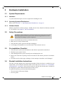
1
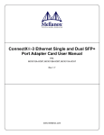
ConnectX®-3 Ethernet Single and Dual QSFP+ Port Adapter Card User Manual P/N: MCX313A-BCBT, MCX314A-BCBT Rev 2.0 www.mellanox.com Rev 1.8 NOTE: THIS HARDWARE, SOFTWARE OR TEST SUITE PRODUCT (“PRODUCT(S)”) AND ITS RELATED DOCUMENTATION ARE PROVIDED BY MELLANOX TECHNOLOGIES “AS-IS” WITH ALL FAULTS OF ANY KIND AND SOLELY FOR THE PURPOSE OF AIDING THE CUSTOMER IN TESTING APPLICATIONS THAT USE THE PRODUCTS IN DESIGNATED SOLUTIONS. THE CUSTOMER'S MANUFACTURING TEST ENVIRONMENT HAS NOT MET THE STANDARDS SET BY MELLANOX TECHNOLOGIES TO FULLY QUALIFY THE PRODUCTO(S) AND/OR THE SYSTEM USING IT. THEREFORE, MELLANOX TECHNOLOGIES CANNOT AND DOES NOT GUARANTEE OR WARRANT THAT THE PRODUCTS WILL OPERATE WITH THE HIGHEST QUALITY. ANY EXPRESS OR IMPLIED WARRANTIES, INCLUDING, BUT NOT LIMITED TO, THE IMPLIED WARRANTIES OF MERCHANTABILITY, FITNESS FOR A PARTICULAR PURPOSE AND NONINFRINGEMENT ARE DISCLAIMED. IN NO EVENT SHALL MELLANOX BE LIABLE TO CUSTOMER OR ANY THIRD PARTIES FOR ANY DIRECT, INDIRECT, SPECIAL, EXEMPLARY, OR CONSEQUENTIAL DAMAGES OF ANY KIND (INCLUDING, BUT NOT LIMITED TO, PAYMENT FOR PROCUREMENT OF SUBSTITUTE GOODS OR SERVICES; LOSS OF USE, DATA, OR PROFITS; OR BUSINESS INTERRUPTION) HOWEVER CAUSED AND ON ANY THEORY OF LIABILITY, WHETHER IN CONTRACT, STRICT LIABILITY, OR TORT (INCLUDING NEGLIGENCE OR OTHERWISE) ARISING IN ANY WAY FROM THE USE OF THE PRODUCT(S) AND RELATED DOCUMENTATION EVEN IF ADVISED OF THE POSSIBILITY OF SUCH DAMAGE. Mellanox Technologies 350 Oakmead Parkway Suite 100 Sunnyvale, CA 94085 U.S.A. www.mellanox.com Tel: (408) 970-3400 Fax: (408) 970-3403 Mellanox Technologies, Ltd. Beit Mellanox PO Box 586 Yokneam 20692 Israel www.mellanox.com Tel: +972 (0)74 723 7200 Fax: +972 (0)4 959 3245 © Copyright 2013. Mellanox Technologies. All Rights Reserved. Mellanox®, Mellanox logo, BridgeX®, ConnectX®, CORE-Direct®, InfiniBridge®, InfiniHost®, InfiniScale®, MLNX-OS®, PhyX®, SwitchX®, UFM®, Virtual Protocol Interconnect® and Voltaire® are registered trademarks of Mellanox Technologies, Ltd. Connect-IB™, FabricIT™, Mellanox Open Ethernet™, Mellanox Virtual Modular Switch™, MetroX™, MetroDX™, ScalableHPC™, Unbreakable-Link™ are trademarks of Mellanox Technologies, Ltd. All other trademarks are property of their respective owners. 2 Mellanox Technologies Document Number: 3688 ConnectX®-3 Ethernet Single and Dual QSFP+ Port Adapter Card User Manual Rev 2.0 Table of Contents Table of Contents . . . . . . . . . . . . . . . . . . . . . . . . . . . . . . . . . . . . . . . . . . . . . . . . . . . . . . . . . . 3 List of Tables . . . . . . . . . . . . . . . . . . . . . . . . . . . . . . . . . . . . . . . . . . . . . . . . . . . . . . . . . . . . . 5 List of Figures . . . . . . . . . . . . . . . . . . . . . . . . . . . . . . . . . . . . . . . . . . . . . . . . . . . . . . . . . . . . . 6 Revision History . . . . . . . . . . . . . . . . . . . . . . . . . . . . . . . . . . . . . . . . . . . . . . . . . . . . . . . . . . . 7 About this Manual . . . . . . . . . . . . . . . . . . . . . . . . . . . . . . . . . . . . . . . . . . . . . . . . . . . . . . . . . 8 Intended Audience . . . . . . . . . . . . . . . . . . . . . . . . . . . . . . . . . . . . . . . . . . . . . . . . . . . . . Related Documentation. . . . . . . . . . . . . . . . . . . . . . . . . . . . . . . . . . . . . . . . . . . . . . . . . . Document Conventions. . . . . . . . . . . . . . . . . . . . . . . . . . . . . . . . . . . . . . . . . . . . . . . . . . Technical Support . . . . . . . . . . . . . . . . . . . . . . . . . . . . . . . . . . . . . . . . . . . . . . . . . . . . . . Firmware and Software Updates. . . . . . . . . . . . . . . . . . . . . . . . . . . . . . . . . . . . . . . . . . . 8 8 8 8 9 Chapter 1 Introduction . . . . . . . . . . . . . . . . . . . . . . . . . . . . . . . . . . . . . . . . . . . . . . . . . . . 10 1.1 1.2 1.3 1.4 Product Overview . . . . . . . . . . . . . . . . . . . . . . . . . . . . . . . . . . . . . . . . . . . . . . . . . 10 Features and Benefits . . . . . . . . . . . . . . . . . . . . . . . . . . . . . . . . . . . . . . . . . . . . . . 11 Operating Systems/Distributions . . . . . . . . . . . . . . . . . . . . . . . . . . . . . . . . . . . . . 11 Connectivity . . . . . . . . . . . . . . . . . . . . . . . . . . . . . . . . . . . . . . . . . . . . . . . . . . . . . 12 Chapter 2 Interfaces . . . . . . . . . . . . . . . . . . . . . . . . . . . . . . . . . . . . . . . . . . . . . . . . . . . . . 13 2.1 2.2 2.3 2.4 Ethernet Interface . . . . . . . . . . . . . . . . . . . . . . . . . . . . . . . . . . . . . . . . . . . . . . . . . 13 PCI Express Interface . . . . . . . . . . . . . . . . . . . . . . . . . . . . . . . . . . . . . . . . . . . . . . 13 I2C-compatible Interface . . . . . . . . . . . . . . . . . . . . . . . . . . . . . . . . . . . . . . . . . . . 14 LED Interface . . . . . . . . . . . . . . . . . . . . . . . . . . . . . . . . . . . . . . . . . . . . . . . . . . . . 14 Chapter 3 Hardware Installation . . . . . . . . . . . . . . . . . . . . . . . . . . . . . . . . . . . . . . . . . . . 15 3.1 System Requirements . . . . . . . . . . . . . . . . . . . . . . . . . . . . . . . . . . . . . . . . . . . . . . 15 3.1.1 Hardware . . . . . . . . . . . . . . . . . . . . . . . . . . . . . . . . . . . . . . . . . . . . . . . . . . . . . . . . 15 3.1.2 Operating Systems/Distributions . . . . . . . . . . . . . . . . . . . . . . . . . . . . . . . . . . . . . 15 3.1.3 Software Stacks. . . . . . . . . . . . . . . . . . . . . . . . . . . . . . . . . . . . . . . . . . . . . . . . . . . 15 3.2 3.3 3.4 Safety Precautions . . . . . . . . . . . . . . . . . . . . . . . . . . . . . . . . . . . . . . . . . . . . . . . . 15 Pre-installation Checklist . . . . . . . . . . . . . . . . . . . . . . . . . . . . . . . . . . . . . . . . . . . 15 Bracket Installation Instructions . . . . . . . . . . . . . . . . . . . . . . . . . . . . . . . . . . . . . . 15 3.4.1 Removing the Existing Bracket . . . . . . . . . . . . . . . . . . . . . . . . . . . . . . . . . . . . . . 16 3.4.2 Installing the New Bracket . . . . . . . . . . . . . . . . . . . . . . . . . . . . . . . . . . . . . . . . . . 16 3.4.2.1 3.4.2.2 3.5 3.6 Gasket Installation . . . . . . . . . . . . . . . . . . . . . . . . . . . . . . . . . . . . . . . . . . . . . . . . . 16 Installing the Bracket. . . . . . . . . . . . . . . . . . . . . . . . . . . . . . . . . . . . . . . . . . . . . . . 17 Card Installation Instructions . . . . . . . . . . . . . . . . . . . . . . . . . . . . . . . . . . . . . . . . 18 Cables and Modules . . . . . . . . . . . . . . . . . . . . . . . . . . . . . . . . . . . . . . . . . . . . . . . 19 3.6.1 Cable Installation . . . . . . . . . . . . . . . . . . . . . . . . . . . . . . . . . . . . . . . . . . . . . . . . . 19 3.7 Identify the Card in Your System . . . . . . . . . . . . . . . . . . . . . . . . . . . . . . . . . . . . . 20 3.7.1 On Windows . . . . . . . . . . . . . . . . . . . . . . . . . . . . . . . . . . . . . . . . . . . . . . . . . . . . . 20 3.7.2 On Linux . . . . . . . . . . . . . . . . . . . . . . . . . . . . . . . . . . . . . . . . . . . . . . . . . . . . . . . . 21 Chapter 4 Driver Installation . . . . . . . . . . . . . . . . . . . . . . . . . . . . . . . . . . . . . . . . . . . . . . 22 4.1 Linux Driver . . . . . . . . . . . . . . . . . . . . . . . . . . . . . . . . . . . . . . . . . . . . . . . . . . . . . 22 4.1.1 Hardware and Software Requirements . . . . . . . . . . . . . . . . . . . . . . . . . . . . . . . . . 22 Mellanox Technologies 3 Rev 2.0 4.1.2 4.1.3 4.1.4 4.1.5 4.2 Installing the Driver . . . . . . . . . . . . . . . . . . . . . . . . . . . . . . . . . . . . . . . . . . . . . . . Loading the Driver . . . . . . . . . . . . . . . . . . . . . . . . . . . . . . . . . . . . . . . . . . . . . . . . Unloading the Driver. . . . . . . . . . . . . . . . . . . . . . . . . . . . . . . . . . . . . . . . . . . . . . . Uninstalling the Driver . . . . . . . . . . . . . . . . . . . . . . . . . . . . . . . . . . . . . . . . . . . . . 22 23 23 23 Windows Driver . . . . . . . . . . . . . . . . . . . . . . . . . . . . . . . . . . . . . . . . . . . . . . . . . . 23 4.2.1 4.2.2 4.2.3 4.2.4 Hardware and Software Requirements . . . . . . . . . . . . . . . . . . . . . . . . . . . . . . . . . Downloading MLNX_WinOF . . . . . . . . . . . . . . . . . . . . . . . . . . . . . . . . . . . . . . . Extracting Files Without Running Installation . . . . . . . . . . . . . . . . . . . . . . . . . . . Installing MLNX_WinOF . . . . . . . . . . . . . . . . . . . . . . . . . . . . . . . . . . . . . . . . . . . 4.2.4.1 4.2.4.2 4.2.5 4.2.6 4.2.7 4.2.8 Attended Installation . . . . . . . . . . . . . . . . . . . . . . . . . . . . . . . . . . . . . . . . . . . . . . . 27 Unattended Installation . . . . . . . . . . . . . . . . . . . . . . . . . . . . . . . . . . . . . . . . . . . . . 32 Upgrading MLNX_WinOF . . . . . . . . . . . . . . . . . . . . . . . . . . . . . . . . . . . . . . . . . . Installation Results . . . . . . . . . . . . . . . . . . . . . . . . . . . . . . . . . . . . . . . . . . . . . . . . OpenSM Activation . . . . . . . . . . . . . . . . . . . . . . . . . . . . . . . . . . . . . . . . . . . . . . . Uninstalling MLNX_WinOF . . . . . . . . . . . . . . . . . . . . . . . . . . . . . . . . . . . . . . . . 4.2.8.1 4.2.8.2 24 24 24 26 33 33 34 35 Attended Uninstall. . . . . . . . . . . . . . . . . . . . . . . . . . . . . . . . . . . . . . . . . . . . . . . . . 35 Unattended Uninstall . . . . . . . . . . . . . . . . . . . . . . . . . . . . . . . . . . . . . . . . . . . . . . . 35 4.2.9 Assigning Port IP After Installation . . . . . . . . . . . . . . . . . . . . . . . . . . . . . . . . . . . 35 4.2.10 Port Type Management on Windows . . . . . . . . . . . . . . . . . . . . . . . . . . . . . . . . . . 37 4.3 VMware Driver . . . . . . . . . . . . . . . . . . . . . . . . . . . . . . . . . . . . . . . . . . . . . . . . . . . 39 4.3.1 Installing and Running the VBI Driver on ESXi-5.x . . . . . . . . . . . . . . . . . . . . . . 39 4.3.2 Installing and Running the offline_bundle Driver on ESXi-5.x . . . . . . . . . . . . . . 40 4.4 4.5 Removing the VIB/offline_bundle Driver . . . . . . . . . . . . . . . . . . . . . . . . . . . . . . 40 FlexBoot . . . . . . . . . . . . . . . . . . . . . . . . . . . . . . . . . . . . . . . . . . . . . . . . . . . . . . . . 40 Chapter 5 Updating Adapter Card Firmware . . . . . . . . . . . . . . . . . . . . . . . . . . . . . . . . 41 Chapter 6 Troubleshooting . . . . . . . . . . . . . . . . . . . . . . . . . . . . . . . . . . . . . . . . . . . . . . . . 43 6.1 6.2 6.3 General . . . . . . . . . . . . . . . . . . . . . . . . . . . . . . . . . . . . . . . . . . . . . . . . . . . . . . . . . 43 Linux . . . . . . . . . . . . . . . . . . . . . . . . . . . . . . . . . . . . . . . . . . . . . . . . . . . . . . . . . . . 44 Windows . . . . . . . . . . . . . . . . . . . . . . . . . . . . . . . . . . . . . . . . . . . . . . . . . . . . . . . . 45 Chapter 7 Specifications . . . . . . . . . . . . . . . . . . . . . . . . . . . . . . . . . . . . . . . . . . . . . . . . . . 46 7.1 7.2 7.3 7.4 7.5 7.6 MCX313A-BCBT Specifications . . . . . . . . . . . . . . . . . . . . . . . . . . . . . . . . . . . . . 46 MCX314A-BCBT Specifications . . . . . . . . . . . . . . . . . . . . . . . . . . . . . . . . . . . . . 47 Adapter LED Operation . . . . . . . . . . . . . . . . . . . . . . . . . . . . . . . . . . . . . . . . . . . . 48 Board Mechanical Drawing and Dimensions . . . . . . . . . . . . . . . . . . . . . . . . . . . . 49 Bracket Mechanical Drawing . . . . . . . . . . . . . . . . . . . . . . . . . . . . . . . . . . . . . . . . 51 Regulatory Statements . . . . . . . . . . . . . . . . . . . . . . . . . . . . . . . . . . . . . . . . . . . . . 52 Appendix A Interface Connectors Pinout . . . . . . . . . . . . . . . . . . . . . . . . . . . . . . . . . . . . 53 A.1 A.2 A.3 Appendix B Appendix C Appendix D Appendix E Appendix F 4 QSFP+ Connector Pinout . . . . . . . . . . . . . . . . . . . . . . . . . . . . . . . . . . . . . . . . 53 PCI Express x8 Connector Pinout . . . . . . . . . . . . . . . . . . . . . . . . . . . . . . . . . 54 I2C-compatible Connector Pinout . . . . . . . . . . . . . . . . . . . . . . . . . . . . . . . . . 55 Finding the MAC and Serial Number on the Adapter Card . . . . . . . . . . 57 Safety Warnings . . . . . . . . . . . . . . . . . . . . . . . . . . . . . . . . . . . . . . . . . . . . . . 58 Avertissements de sécurité d’installation (Warnings in French) . . . . . . 60 Sicherheitshinweise (Warnings in German) . . . . . . . . . . . . . . . . . . . . . . . 62 Advertencias de seguridad para la instalación (Warnings in Spanish) . 64 Mellanox Technologies ConnectX®-3 Ethernet Single and Dual QSFP+ Port Adapter Card User Manual Rev 2.0 List of Tables Table 1: Revision History Table . . . . . . . . . . . . . . . . . . . . . . . . . . . . . . . . . . . . . . . . . . . . . . . . . . . 7 Table 2: Documents List . . . . . . . . . . . . . . . . . . . . . . . . . . . . . . . . . . . . . . . . . . . . . . . . . . . . . . . . . 8 Table 3: Single and Dual-port 40 Gigabit Ethernet Adapter Cards. . . . . . . . . . . . . . . . . . . . . . . . 10 Table 4: Features . . . . . . . . . . . . . . . . . . . . . . . . . . . . . . . . . . . . . . . . . . . . . . . . . . . . . . . . . . . . . . 11 Table 5: Software and Hardware Requirements . . . . . . . . . . . . . . . . . . . . . . . . . . . . . . . . . . . . . . 22 Table 6: Software and Hardware Requirements . . . . . . . . . . . . . . . . . . . . . . . . . . . . . . . . . . . . . . 24 Table 7: MCX313A-BCBT Specifications Table . . . . . . . . . . . . . . . . . . . . . . . . . . . . . . . . . . . . . 46 Table 8: MCX314A-BCBT Specifications Table . . . . . . . . . . . . . . . . . . . . . . . . . . . . . . . . . . . . . 47 Table 9: Physical and Logical Link Indication . . . . . . . . . . . . . . . . . . . . . . . . . . . . . . . . . . . . . . . 48 Mellanox Technologies 5 Rev 2.0 List of Figures Figure 1: MCX314A-BCBT Card . . . . . . . . . . . . . . . . . . . . . . . . . . . . . . . . . . . . . . . . . . . . . . . . . . 13 Figure 2: I2C-compatible Connector . . . . . . . . . . . . . . . . . . . . . . . . . . . . . . . . . . . . . . . . . . . . . . . . 14 Figure 3: Bracket Screws . . . . . . . . . . . . . . . . . . . . . . . . . . . . . . . . . . . . . . . . . . . . . . . . . . . . . . . . . 16 Figure 4: Gasket Location on Adapter Card . . . . . . . . . . . . . . . . . . . . . . . . . . . . . . . . . . . . . . . . . . 17 Figure 5: Gasket Installation . . . . . . . . . . . . . . . . . . . . . . . . . . . . . . . . . . . . . . . . . . . . . . . . . . . . . . 17 Figure 6: Placing the Bracket on the Card . . . . . . . . . . . . . . . . . . . . . . . . . . . . . . . . . . . . . . . . . . . . 18 Figure 7: PCI Device . . . . . . . . . . . . . . . . . . . . . . . . . . . . . . . . . . . . . . . . . . . . . . . . . . . . . . . . . . . . 20 Figure 8: Support Download Assistant . . . . . . . . . . . . . . . . . . . . . . . . . . . . . . . . . . . . . . . . . . . . . . 42 Figure 9: Mechanical Drawing of the Single-port MCX313A-BCBT Adapter Card . . . . . . . . . . . 49 Figure 10: Mechanical Drawing of the Dual-port MCX314A-BCBT Adapter Card . . . . . . . . . . . . 50 Figure 11: Dual-port Bracket . . . . . . . . . . . . . . . . . . . . . . . . . . . . . . . . . . . . . . . . . . . . . . . . . . . . . . . 51 Figure 12: Single-port Bracket . . . . . . . . . . . . . . . . . . . . . . . . . . . . . . . . . . . . . . . . . . . . . . . . . . . . . 51 Figure 13: Connector and Cage Views . . . . . . . . . . . . . . . . . . . . . . . . . . . . . . . . . . . . . . . . . . . . . . . 53 Figure 14: PCIe Connector Pinout . . . . . . . . . . . . . . . . . . . . . . . . . . . . . . . . . . . . . . . . . . . . . . . . . . . 55 Figure 15: Compatible Connector Plug and Pinout . . . . . . . . . . . . . . . . . . . . . . . . . . . . . . . . . . . . . . 55 Figure 16: Card Product Label (Example) . . . . . . . . . . . . . . . . . . . . . . . . . . . . . . . . . . . . . . . . . . . . . 57 6 Mellanox Technologies ConnectX®-3 Ethernet Single and Dual QSFP+ Port Adapter Card User Manual Rev 2.0 Revision History This document was printed on June 27, 2013. Table 1 - Revision History Table Date Rev Comments/Changes June 2013 2.0 Updated User Manual structure February 2013 1.8 • • • Added Section 4.3, “VMware Driver,” on page 39 Updated Figure 7, “PCI Device,” on page 20 and Figure 8, “Device Manager,” on page 58 Updated all Web links in the User Manua - lFigure 10, “Mechanical Drawing of the Dual- port MCX314A-BCBT Adapter Card,” on page 50 November 2012 1.77 • - Updated Web links in the following locations: - Section 6.5.1, “Software Requirements,” on page 59 - Table 7, “MCX313A-BCBT Specifications Table,” on page 46 Table 8, “MCX314A-BCBT Specifications Table,” on page 47 October 2012 1.6 • • Fixed Table 5, “Jumper Configuration,” on page 17 Updated figures in Section 4.2, “Windows Driver,” on page 23 by providing ConnectX-3 examples August 2012 1.5 • Added operational and non-operational temperature and humidity level to the following tables: - Table 7, “MCX313A-BCBT Specifications Table,” on page 46 - Table 8, “MCX314A-BCBT Specifications Table,” on page 47 May 2012 1.4 • Removed “Blinking indicates a problem with the physical link” from Table 9, “Physical and Logical Link Indication,” on page 48 April 2012 1.3 • Updated power numbers in Table 7, “MCX313A-BCBT Specifications Table,” on page 46 and Table 8, “MCX314A-BCBT Specifications Table,” on page 47 January 2012 1.2 • • Minor edits Updated LED functions in Section 2.3, “I2C-compatible Interface,” on page 14 Formatted specification tables in Appendix 7, “Specifications,” on page 46 • October 2011 1.1 Added new OPNs based on ConnectX-3 Step A1 devices July 2011 1.0 Minor edits July 2011 0.10 First Release Mellanox Technologies 7 Rev 2.0 About this Manual This User Manual describes Mellanox Technologies ConnectX®-3 40 Gigabit Ethernet Single and Dual QSFP+ port PCI Express x8 adapter cards. It provides details as to the interfaces of the board, specifications, required software and firmware for operating the board, and relevant documentation. Intended Audience This manual is intended for the installer and user of these cards. The manual assumes basic familiarity with Ethernet networks and architecture specifications. Related Documentation Table 2 - Documents List Mellanox Firmware Tools (MFT) User Manual Document no. 2204UG User Manual describing the set of MFT firmware management tools for a single node. See http://www.mellanox.com => Products => Software => Firmware Tools MLNX_EN for Linux README Driver Kit for Mellanox Adapter Cards with 1040GigE Support Document no. 2950 This document provides information on the MLNX_EN Linux driver and instructions for installing the driver on Mellanox ConnectX adapter cards supporting 10/40Gb/s Ethernet. WinOF VPI for Windows User Manual Document no. 3280 User Manual describing WinOF features, performance, InfiniBand diagnostic, tools content and configuration. See http://www.mellanox.com => Products => Software => Windows SW/Drivers => Mellanox OFED for Windows (WinOF) Mellanox MLX4_EN Driver for VMware README Document no. 3527 User Manual describing MLX4_EN driver for WMware features, performance, diagnostic, tools content and configuration. See http://www.mellanox.com => Products => Software => Ethernet Drivers => VMware Drivers IEEE Std 802.3 Specification This is the IEEE Ethernet specification http://standards.ieee.org/getieee802 PCI Express 3.0 Specifications Industry Standard PCI Express 3.0 Base and Card Electromechanical Specifications Document Conventions When discussing memory sizes, MB and MBytes are used in this document to mean size in mega Bytes. The use of Mb or Mbits (small b) indicates size in mega bits. In this document PCIe is used to mean PCI Express. Technical Support Customers who purchased Mellanox products directly from Mellanox are invited to contact us through the following methods. 8 Mellanox Technologies ConnectX®-3 Ethernet Single and Dual QSFP+ Port Adapter Card User Manual • URL: http://www.mellanox.com => Support • E-mail: [email protected] • Tel: +1.408.916.0055 Rev 2.0 Customers who purchased Mellanox M-1 Global Support Services, please see your contract for details regarding Technical Support. Customers who purchased Mellanox products through a Mellanox approved reseller should first seek assistance through their reseller. Firmware and Software Updates The Mellanox support downloader contains software, firmware and knowledge database information for Mellanox products. Access the database from the Mellanox Support web page, http://www.mellanox.com => Support or use the following link to go directly to the Mellanox Support Download Assistant page, http://www.mellanox.com/supportdownloader/. Mellanox Technologies 9 Rev 2.0 1 Introduction Introduction This is the User Guide for Mellanox Technologies Ethernet adapter cards based on the ConnectX®-3 EN integrated circuit device. These adapters connectivity provide the highest performing and most flexible interconnect solution for PCI Express Gen3 servers used in Enterprise Data Centers, High-Performance Computing, and Embedded environments This chapter covers the following topics: 1.1 • Section 1.1, “Product Overview,” on page 10 • Section 1.2, “Features and Benefits,” on page 11 • Section 1.3, “Operating Systems/Distributions,” on page 11 • Section 1.4, “Connectivity,” on page 12 Product Overview The following tables provide the ordering part number, port speed, number of ports, and PCI Express speed. Each adapter comes with two bracket heights - short and tall. Table 3 - Single and Dual-port 40 Gigabit Ethernet Adapter Cards Ordering Part Number (OPN) Data Transmission Rate 10 MCX31[4/3]A-BCBT 40GigE Number of ports MCX314A-BCBT: dual-port QSFP+ MCX313A-BCBT: single-port QSFP+ PCI Express SERDES Speed PCIe 3.0 x8 8GT/s RoHS R6 Adapter IC Part Number MT27518A1-FCCR-BE Device ID (decimal) 4099 for Physical Function 4100 for Virtual Function Mellanox Technologies ConnectX®-3 Ethernet Single and Dual QSFP+ Port Adapter Card User Manual 1.2 Rev 2.0 Features and Benefits Table 4 - Features PCI Express (PCIe) Uses PCIe Gen 3.0 (1.1 and 2.0 compatible) through an x8 edge connector up to 8GT/s 10/40/56 Gigabit Ethernet Mellanox adapters comply with the following IEEE 802.3* standards: IEEE Std 802.3-2008 Ethernet IEEE Std 802.3ae 10 Gigabit Ethernet IEEE Std 802.3ba 40 Gigabit Ethernet IEEE Std 802.3ad Link Aggregation and Failover Memory PCI Express - stores and accesses InfiniBand and/or Ethernet fabric connection information and packet data SPI - includes one 16MB SPI Flash device (M25PX16-VMN6P device by ST Microelectronics) EEPROM - accessible through the I2C-compatible interface. The EEPROM capacity is 4Kb. RDMA over Converged Ethernet (RoCE) Leveraging Data Center Bridging capabilities, RoCE provides efficient low latency RDMA services over Layer 2 Ethernet. CPU offload Adapter functionality enabling reduced CPU overhead allowing more available CPU GPUDirect RDMA Using GPUDirect RDMA, adapters can directly read and write CUDA host and device memory, eliminating unnecessary system memory copies and CPU overhead, resulting in significant performance improvements. Sockets Acceleration 1.3 Applications utilizing TCP/UDP/IP transport can achieve industry leading throughput over InfiniBand or 10 or 40GbE. The hardware-based stateless offload engines in ConnectX-3 reduce the CPU overhead of IP packet transport. Sockets acceleration software further increases performance for latency sensitive applications. Quality of Service (QoS) Support for port-based Quality of Service enabling various application requirements for latency and SLA Hardware-based I/O virtualization ConnectX-3 provides dedicated adapter resourcesand guaranteed isolation and protection for virtual machines within the server. SR-IOV ConnectX-3 Pro SR-IOV technology provides dedicated adapter resources and guaranteed isolation and protection for virtual machines (VM) within the server. I/O virtualization with ConnectX-3 Pro gives data center managers better server utilization while reducing cost, power, and cable complexity. Storage Acceleration A consolidated compute and storage network achieves significant cost-performance advantages over multi-fabric networks. Standard block and file access protocols can leverage InfiniBand RDMA for high-performance storage access. Operating Systems/Distributions • Citrix XenServer 6.1 Mellanox Technologies 11 Rev 2.0 1.4 12 Introduction • Novell SLES, Red Hat Enterprise Linux(RHEL), and other Linux distributions • Microsoft Windows Server 2008/2012 • OpenFabrics Enterprise Distribution (OFED) • OpenFabrics Windows Distribution (WinOF) • Ubuntu 12.04 • VMware ESXi 4.x and 5.x Connectivity • Interoperable with InfiniBand or 10/40 Gb Ethernet switches. Interoperable with 56GbE Mellanox Switches. • Passive copper cable with ESD protection • Powered connectors for optical and active cable support • QSFP to SFP+ connectivity through QSA module Mellanox Technologies ConnectX®-3 Ethernet Single and Dual QSFP+ Port Adapter Card User Manual 2 Rev 2.0 Interfaces Each adapter card includes the following interfaces: • “Ethernet Interface” • “PCI Express Interface” • “I2C-compatible Interface” • “LED Interface” Figure 1: MCX314A-BCBT Card The adapter cards include special circuits to protect from ESD shocks to the card/server when plugging copper cables. 2.1 Ethernet Interface The network ports of the ConnectX®-3 adapter cards are compliant with the IEEE 802.3 Ethernet standards listed in Table 4, “Features,” on page 11. Ethernet traffic is transmitted through the cards' QSFP+ connectors. 2.2 PCI Express Interface The ConnectX®-3 adapter cards support PCI Express 3.0 (1.1 and 2.0 compatible) through an x8 edge connector. The device can be either a master initiating the PCI Express bus operations or a slave responding to PCI bus operations. The following lists the PCIe interface features: • PCIe Base 3.0 compliant, 1.1 and 2.0 compatible • 2.5, 5.0, or 8.0GT/s link rate x8 • Auto-negotiates to x8, x4, x2, or x1 Mellanox Technologies 13 Rev 2.0 • 2.3 Interfaces Support for MSI/MSI-X mechanisms I2C-compatible Interface A three-pin header on the adapter cards is provided as the I2C-compatible interface. See Figure 10, “Mechanical Drawing of the Dual-port MCX314A-BCBT Adapter Card,” on page 50 for the location on the board. Figure 2: I2C-compatible Connector 2.4 LED Interface There are two I/O LEDs per port. For LED specifications please refer to Section 7.3, “Adapter LED Operation,” on page 48 14 Mellanox Technologies ConnectX®-3 Ethernet Single and Dual QSFP+ Port Adapter Card User Manual 3 Hardware Installation 3.1 System Requirements 3.1.1 Hardware Rev 2.0 A system with a PCI Express x8 slot is required for installing the card. 3.1.2 Operating Systems/Distributions Please refer to Section 1.3, “Operating Systems/Distributions,” on page 11. 3.1.3 Software Stacks Mellanox OpenFabric software package - MLNX_EN for Linux, WinOF for Windows and ESX 5.1 for VMware. See Chapter 4, “Driver Installation”. 3.2 Safety Precautions The adapter is being installed in a system that operates with voltages that can be lethal. Before opening the case of the system, observe the following precautions to avoid injury and prevent damage to system components. 1. Remove any metallic objects from your hands and wrists. 2. Make sure to use only insulated tools. 3. Verify that the system is powered off and is unplugged. 4. It is strongly recommended to use an ESD strap or other antistatic devices. 3.3 Pre-installation Checklist 1. Verify that your system meets the hardware and software requirements stated above. 2. Shut down your system if active. 3. After shutting down the system, turn off power and unplug the cord. 4. Remove the card from its package. Please note that the card must be placed on an antistatic surface. 5. Check the card for visible signs of damage. Do not attempt to install the card if damaged. 3.4 Bracket Installation Instructions The card is usually shipped with a tall bracket installed. If this form factor is suitable for your requirements, you can skip the remainder of this section and move to Section 3.5, “Card Installation Instructions,” on page 18. If you need to replace it with the short bracket that is included in the shipping box, please follow the instructions in this section. To replace the bracket you will need the following parts: • The new bracket of the proper height • One new gasket Mellanox Technologies 15 Rev 2.0 3.4.1 Hardware Installation • The 2 screws saved from the removal of the bracket • The 2 fiber washers saved from the removal of the bracket Removing the Existing Bracket Figure 3: Bracket Screws Screws 1. Remove the two screws holding the bracket in place. The bracket comes loose from the card. Be careful not to put stress on the LEDs. 2. Save the two screws and the two fiber washers. 3.4.2 Installing the New Bracket 3.4.2.1 Gasket Installation Note: The following instructions relate to the installation of the gasket for adapter cards that are not shipped with a gasket already installed. Mellanox Technologies now provides all ConnectX3 adapter cards with the gasket already installed unto the bracket. 1. Remove the paper to expose the adhesive on the gasket. 2. Place the gasket onto the new bracket. Make sure to correctly align the gasket with the hole in the bracket. 3. If the old gaskets are still on the card, remove them before installing the new bracket. 16 Mellanox Technologies ConnectX®-3 Ethernet Single and Dual QSFP+ Port Adapter Card User Manual Rev 2.0 Figure 4: Gasket Location on Adapter Card Gasket Figure 5: Gasket Installation 3.4.2.2 Installing the Bracket 1. Place the bracket onto the card until the screw holes line up. See Figure 6. Do not force the bracket onto the card. You may have to gently push the LEDs using a small screwdriver to align the LEDs with the holes in the bracket. 2. Screw on the bracket using the screws and washers saved from the bracket removal procedure above. Mellanox Technologies 17 Rev 2.0 Hardware Installation Figure 6: Placing the Bracket on the Card 3. Make sure that the LEDs are aligned onto the bracket holes. 4. Use a torque driver to apply up to 2 lbs-in torque on the screws. 3.5 Card Installation Instructions 1. Before installing the card, make sure that the system is off and the power cord is not connected to the server. Please follow proper electrical grounding procedures. 2. Open the system case. 3. Place the adapter in an available PCI Express slot. A lesser width adapter can be seated into a greater width slot (x4 in a x8), but a greater width adapter cannot be seated into a lesser width slot (x8 in a x4). Align the adapter connector edge with the PCI Express connector slot. 4. Applying even pressure at both corners of the card, insert the adapter card into the slot until it is firmly seated. When the adapter is properly seated, the adapter port connectors are aligned with the slot opening, and the adapter faceplate is visible against the system chassis. 18 Mellanox Technologies ConnectX®-3 Ethernet Single and Dual QSFP+ Port Adapter Card User Manual Rev 2.0 Do not use excessive force when seating the card, as this may damage the system or the adapter. 5. Secure the adapter with the adapter clip or screw. 6. Close the system case. 3.6 Cables and Modules To obtain the list of supported cables for your adapter, please refer to “Mellanox Products Approved Cable Lists” at: www.mellanox.com/related-docs/user_manuals/Mellanox_approved_cables.pdf. 3.6.1 Cable Installation 1. All cables can be inserted or removed with the unit powered on. 2. To insert a cable, press the connector into the port receptacle until the connector is firmly seated. When installing cables make sure that the latches engage. Always install and remove cables by pushing or pulling the cable and connector in a straight line with the card. 3. After inserting a cable into a port, the Green LED indicator will light when the physical connection is established (that is, when the unit is powered on and a cable is plugged into the port with the other end of the connector plugged into a functioning port). See Section 7.3, “Adapter LED Operation,” on page 48. 4. After plugging in a cable, lock the connector using the latching mechanism particular to the cable vendor. When a logical connection is made the Yellow LED will light. When data is being transferred the yellow led will blink. See Section 7.3, “Adapter LED Operation,” on page 48. 5. Care should be taken as not to impede the air exhaust flow through the ventilation holes. Use cable lengths which allow for routing horizontally around to the side of the chassis before bending upward or downward in the rack. 6. To remove a cable, disengage the locks and slowly pull the connector away from the port receptacle. Both LED indicators will turn off when the cable is unseated. a. Mellanox Technologies 19 Rev 2.0 Hardware Installation 3.7 Identify the Card in Your System 3.7.1 On Windows 1. Open Device Manager on the server. Click start => Run, and then enter “devmgmt.msc”. 2. Expand System Devices and locate your Mellanox ConnectX-3 adapter card. 3. Right click the mouse on your adapter's row and select properties to display the adapter card properties window. 4. Click the Details tab and select Device Instance Id (Windows 2003) or 5. Hardware Ids (Windows 2008/R2) from the Properties pull-down menu. Figure 7: PCI Device 6. In the Value display box, check the fields VEN and DEV (fields are separated by ‘&’). In the display example above, notice the sub-string “PCI\VEN_15B3&DEV_1003”: VEN is equal to 0x15B3 – this is the Vendor ID of Mellanox Technologies; and DEV is equal to 1003 – this is a valid Mellanox Technologies PCI Device ID. If the PCI device does not have a Mellanox adapter ID, return to Step 2 to check another device. The list of Mellanox Technologies PCI Device IDs can be found in the PCI ID repository at http://pci-ids.ucw.cz/read/PC/15b3. 20 Mellanox Technologies ConnectX®-3 Ethernet Single and Dual QSFP+ Port Adapter Card User Manual 3.7.2 Rev 2.0 On Linux Get the device location on the PCI bus by running lspci and locating lines with the string “Mellanox Technologies”: > lspci |grep -i Mellanox 27:00.0 Network controller: Mellanox Technologies MT27500 Family [ConnectX-3] Mellanox Technologies 21 Rev 2.0 Driver Installation 4 Driver Installation 4.1 Linux Driver For Linux, download and install the latest MLNX_EN driver software package available via the Mellanox web site at: http://www.mellanox.com => Products => Software => Ethernet Drivers => ConnectX®-3 EN 10/40GigE Linux Driver => Download. Follow the installation instructions included in the download package (also available from the download page). 4.1.1 Hardware and Software Requirements Table 5 - Software and Hardware Requirements Requirements Platforms Description CPU architectures: • • • For the latest list of device IDs, please visit http://pci-ids.ucw.cz/read/PC/ 15b3. Device ID Operating System Linux Operating Systems: • • • • • • • • Software Dependencies 4.1.2 x86_64 x86 power-pc RedHat EL5.8 RedHat EL5.9 RedHat EL6.2 RedHat EL6.3 OEL6.2 + 2.6.32-279.19.1 OEL6.3 + 2.6.32-279.19.1 SLES11 SP1 SLES11 SP2 To install the driver software, kernel sources must be installed on the machine. MLNX_EN driver cannot coexist with OFED software on the same machine. Hence when installing MLNX_EN all OFED packages should be removed (done by the mlnx_en install script) Installing the Driver Step 1. Download Driver Package Please download the current driver package from http://www.mellanox.com => Products => Software => Ethernet Driver => Linux Driver => Download. Step 2. Install Driver Run the following commands to install the driver: #> tar xzvf mlnx_en-1.5.10.tgz file #> cd mlnx_en-1.5.10 #> ./install.sh The package consists of several source RPMs. The install script rebuilds the source RPMs and then installs the created binary RPMs. The created kernel module binaries are placed under /lib/ 22 Mellanox Technologies ConnectX®-3 Ethernet Single and Dual QSFP+ Port Adapter Card User Manual Rev 2.0 modules/<kernel-ver>/updates/kernel/drivers/net/mlx4. mlnx_en installer supports 2 modes of installation.The install scripts selects the mode of driver installation depending of the running OS/kernel version. 1. Kernel Module Packaging (KMP) mode, where the source rpm is rebuilt for each installed flavor of the kernel. This mode is used for RedHat and SUSE distributions. 2. Non KMP installation mode, where the sources are rebuilt with the running kernel. This mode is used for vanilla kernels. Note: If the Vanilla kernel is installed as rpm, please use the "--disable-kmp" flag when installing the driver. The kernel module sources are placed under /usr/src/mellanox-mlnx-en-1.5.10/.Run the following commands to recompile the driver: #> #> #> #> cd /usr/src/mellanox-mlnx-en-1.5.10/ scripts/mlnx_en_patch.sh make make install The uninstall and performance tuning scripts are installed. Note: If the driver was installed without kmp support, the sources would be located under /usr/ srs/mlnx_en-1.5.10/ 4.1.3 Loading the Driver Step 1. Make sure no previous driver version is currently loaded Run: #> modprobe -r mlx4_en Step 2. Load the new driver version Run: #> modprobe mlx4_en The result is a new net-device appearing in 'ifconfig -a' output. 4.1.4 Unloading the Driver To unload the Ethernet driver run: #> modprobe mlx4_en 4.1.5 Uninstalling the Driver To uninstall the mlnx_en driver run: #> /sbin/mlnx_en_uninstall.sh 4.2 Windows Driver For Windows, download and install the latest Mellanox WinOF VPI for Windows software package available via the Mellanox web site at: http://www.mellanox.com. Download this package Mellanox Technologies 23 Rev 2.0 Driver Installation from the Mellanox web site at: http://www.mellanox.com => Products => Software => Ethernet Drivers => Windows SW/Driver => Download. Follow the installation instructions included in the download package (also available from the download page). 4.2.1 Hardware and Software Requirements Table 6 - Software and Hardware Requirements Requirements 4.2.2 Description Required Disk Space for Installation 100 MB Operating Systems Windows Server 2012 (64 bit only) Windows Server 2008 R2 (64 bit only) Installer Privileges The installation requires administrator privileges on the target machine. Downloading MLNX_WinOF Follow these steps to download the .exe according to your Operating System. Step 1. Verify the machine architecture. 1. Open a CMD console (Click start-->Run and enter CMD). 2. Enter the following command: > echo %PROCESSOR_ARCHITECTURE% On an x64 (64-bit) machine, the output will be “AMD64”. Step 2. Go to the MLNX_WinOF for Windows Web page at http://www.mellanox.com => Products => Software => Ethernet Drivers => Windows SW/ Drivers. Step 3. Download the .exe image according to the architecture of your machine (see Step 1.). The name of the .exe is in the following format MLNX_VPI_WinOF-<version>_All_<OS>_<arch>.exe. Installing the incorrect .exe file is prohibited. If you do so, an error message will be displayed. For example, if you try to install a 64-bit .exe on a 32-bit machine, the wizard will display the following (or a similar) error message: 4.2.3 Extracting Files Without Running Installation To extract the files without running installation, perform the following steps. Step 1. 24 Open a CMD console (Click Start-->Run and enter CMD). Mellanox Technologies ConnectX®-3 Ethernet Single and Dual QSFP+ Port Adapter Card User Manual Step 2. Rev 2.0 Enter the following command: MLNX_VPI_WinOF-<version>_All_<OS>_<arch>.exe /a Step 3. Click Next to create a server image. Step 4. Click Change and specify the location in which the files are extracted to. Mellanox Technologies 25 Rev 2.0 4.2.4 Driver Installation Step 5. Click Install to extract this folder, or click Change to install to a different folder. Step 6. To complete the extraction, click Finish. Installing MLNX_WinOF This section provides instructions for two types of installation procedures: • “Attended Installation” An installation procedure that requires frequent user intervention. • 26 “Unattended Installation” Mellanox Technologies ConnectX®-3 Ethernet Single and Dual QSFP+ Port Adapter Card User Manual Rev 2.0 An automated installation procedure that requires no user intervention. Both Attended and Unattended installations require administrator privileges. 4.2.4.1 Attended Installation The following is an example of a MLNX_WinOF_win8 x64 installation session. Step 1. Double click the .exe and follow the GUI instructions to install MLNX_WinOF. To configure your setup to contain the logs option, please run the following command after opening a CMD console: MLNX_VPI_WinOF-4_40_0_All_win8_x64.exe /v"/l*vx [LogFile]" If you do not want to upgrade your firmware version, run the following command: MLNX_VPI_WinOF-4_40_0_All_win8_x64.exe /v" MT_SKIPFWUPGRD=1" For further help, please run: MLNX_VPI_WinOF-4_40_0_All_win8_x64.exe /v" /h" Step 2. Click Next in the Welcome screen. Mellanox Technologies 27 Rev 2.0 Driver Installation Step 3. Read then accept the license agreement and click Next. Step 4. Select the target folder for the installation. Step 5. The firmware upgrade screen will be displayed in the following cases: • 28 If the user has an OEM card, in this case the firmware will not be updated. Mellanox Technologies ConnectX®-3 Ethernet Single and Dual QSFP+ Port Adapter Card User Manual • Step 6. Rev 2.0 If the user has a standard Mellanox card, and the firmware version is older than the one specified in WinOF Installation Guide 4.40, the firmware will be updated accordingly. However, if the user has both OEM card and Mellanox card, only Mellanox card will be updated. Configure your system for maximum performance by checking the maximum performance box. Mellanox Technologies 29 Rev 2.0 Driver Installation This step requires rebooting your machine at the end of the installation. Step 7. Select a Complete or Custom installation, follow Step a and on, on page 30. a. 30 Select the desired feature to install: • OpenSM - installs Windows OpenSM that is required to mange the subnet from a host. OpenSM is part of the driver and installed automatically. • Performances tools - install the performance tools that are used to measure the InfiniBand performance in user environment. • Analyze tools - install the tools that can be used either to diagnosed or analyzed the InfiniBand environment. • SDK - contains the libraries and DLLs for developing InfiniBand application over IBAL. • Documentation: contains the User Manual and Installation Guide. • ND FLTR DLLs: contains the files for standalone installation of the mlx4nd provider. Mellanox Technologies ConnectX®-3 Ethernet Single and Dual QSFP+ Port Adapter Card User Manual b. Rev 2.0 Click Install to start the installation. Mellanox Technologies 31 Rev 2.0 Driver Installation Step 8. Click Finish to complete the installation. If the firmware upgrade fails, the following message will be displayed. 4.2.4.2 Unattended Installation The following is an example of a MLNX_WinOF_win8 x64 unattended installation session. Step 1. Open the CMD console (click Start > Run and enter ‘cmd’) Step 2. Install the driver. Run: > MLNX_VPI_WinOF-4_40_0_All_win8_x64.exe /S /v"/qn" 32 Mellanox Technologies ConnectX®-3 Ethernet Single and Dual QSFP+ Port Adapter Card User Manual Step 3. Rev 2.0 [Optional] To configure your setup to contain the logs option, please run the following command: > MLNX_VPI_WinOF-4_40_0_All_win8_x64.exe /S /v"/qn" /v"/l*vx [LogFile]" Step 4. [Optional] If you do not want to upgrade your firmware version, run the following command: > MLNX_VPI_WinOF-4_40_0_All_win8_x64.exe /S /v"/qn" /v" MT_SKIPFWUPGRD=1" For further help, please run: > MLNX_VPI_WinOF-4_40_0_All_win8_x64.exe /v" /h" 4.2.5 Upgrading MLNX_WinOF The MLNX_WinOF driver upgrades automatically MLNX_WinOF Windows 2008R2 driver by uninstalling the previous version and installs the new driver. However, MLNX_WinOF driver upgrade in Windows 2012 driver do not completely uninstall the previous version. 4.2.6 • In Windows 2012 (MLNX_WinOF Rev. 4.2 and above), the network configuration is saved upon driver upgrade. • In Windows 2008 R2 the existing configuration files are not saved upon driver upgrade. Installation Results Upon installation completion, you can verify the successful addition of the network card(s) through the Device Manager. To see the Mellanox network adapter device, and the Ethernet or Mellanox Technologies 33 Rev 2.0 Driver Installation IPoIB network device (depending on the used card) for each port, display the Device Manager and expand “System devices” or “Network adapters”. 4.2.7 OpenSM Activation OpenSM is a service required by managed networks in InfiniBand environments, and must be activated in one of the machines running on the subnet, otherwise the interface link will not come up. If the cards are connected to a managed network, there is no need to run OpenSM. Only one OpenSM should run per subnet. In Ethernet interfaces, running OpenSM is not required. OpenSM does not run as a service during installation as it requires the GUID parameter to decide on which port to work. Setting OpenSM upon setup results in it working only for the first port and not for the others. To run OpenSM as a service, assuming the package was installed in the default path, use: sc create OpenSM1 binPath= "c:\Program Files\Mellanox\MLNX_VPI\IB\Tools\ opensm.exe --service" start=auto" To start the service, run: sc start opensm For further information, please refer to the “OpenSM - Subnet Manager” chapter in the User Manual. 34 Mellanox Technologies ConnectX®-3 Ethernet Single and Dual QSFP+ Port Adapter Card User Manual 4.2.8 Rev 2.0 Uninstalling MLNX_WinOF 4.2.8.1 Attended Uninstall To uninstall MLNX_WinOF on a single node, perform one of the following options: 1. Click Start-> Control Panel-> Programs and Features-> MLNX_VPI-> Uninstall. (NOTE: This requires elevated administrator privileges.) 2. Double click the .exe and follow the instructions of the install wizard. 3. Click Start-> All Programs-> Mellanox Technologies-> MLNX_WinOF-> Uninstall MLNX_WinOF. 4.2.8.2 Unattended Uninstall To uninstall MLNX_WinOF in unattended mode, perform the following: Step 1. Open a CMD console. Step 2. Uninstall the driver. Run: MLNX_VPI_WinOF-4_40_0_All_win8_x64.exe /S /x /v"/qn" 4.2.9 Assigning Port IP After Installation By default, your machine is configured to obtain an automatic IP address via a DHCP server. In some cases, the DHCP server may require the MAC address of the network adapter installed in your machine. To obtain the MAC address: Step 1. Open a CMD console Step 2. Display the MAC address as “Physical Address” ipconfig /all Configuring a static IP is the same for both IPoIB and Ethernet adapters. To assign a static IP address to a network port after installation: Step 1. Open the Network Connections window. Locate Local Area Connections with Mellanox devices. Mellanox Technologies 35 Rev 2.0 36 Driver Installation Step 2. Right-click a Mellanox Local Area Connection and left-click Properties. Step 3. Select Internet Protocol Version 4 (TCP/IPv4) from the scroll list and click Properties. Mellanox Technologies ConnectX®-3 Ethernet Single and Dual QSFP+ Port Adapter Card User Manual Rev 2.0 Step 4. Select the “Use the following IP address:” radio button and enter the desired IP information. Step 5. Click OK. Step 6. Close the Local Area Connection dialog. Step 7. Verify the IP configuration by running ‘ipconfig’ from a CMD console. > ipconfig ... Ethernet adapter Local Area Connection 4: Connection-specific IP Address. . . . . Subnet Mask . . . . Default Gateway . . DNS . . . . . . Suffix . . . . . . . . . . . . . . . . : : 11.4.12.63 : 255.255.0.0 : ... 4.2.10 Port Type Management on Windows After installing Mellanox WinOF VPI for Windows on your machine, you can change a port's protocol configuration. The following steps describe how to configure the port type: Step 1: Display the Device Manager and expand “System Devices”. Mellanox Technologies 37 Rev 2.0 Driver Installation Step 2: Right-click on the Mellanox ConnectX VPI network adapter and left-click Properties. Select the Port Protocol tab from the Properties sheet. Note: The “Port Protocol” tab is displayed only if the NIC is a VPI (IB and ETH). If the NIC is either only IB or ETH, the tab will not be shown. 38 Mellanox Technologies ConnectX®-3 Ethernet Single and Dual QSFP+ Port Adapter Card User Manual Rev 2.0 Step 3. In this step, you can perform two different functions: (a) Choose the desired port protocol for the available port(s), and (b) activate or deactivate the WSD, ND, and/or SDP ULPs. Note: IB must be always the first port in Port 1. If you choose ETH as your first port in Port 1, then the second port in Port 2 can be only ETH. Note: WSD is not supported in Windows 7. Consequently, on this OS the WSD checkbox is grayed out and cannot be selected. 4.3 VMware Driver For VMware download and install the latest Mellanox OFED Driver for VMware® ESXi Serversoftware package available via the Mellanox web site at: http://www.mellanox.com => Products => Software => Ethernet Drivers => VMware Drivers => Download. Follow the installation instructions included in the download package (also available from the download page). 4.3.1 Installing and Running the VBI Driver on ESXi-5.x 1. Log into the VMware ESXi server machine as root. 2. You can either: a. Remove any earlier version of the driver from your VMware ESXi server machine prior to installing the new version. Run: #> esxcli software vib list #> esxcli software vib remove –n net-mlx4-en b. Install the mlx4_en driver VIB package. Run: #> esxcli software vib install –v <vib_url> c. Reboot ESXi server (The driver will be loaded automatically). OR a. Update the driver. Run: #> esxcli software vib update –v <vib_url> b. Reboot ESXi server (The driver will be loaded automatically). » To verify that the driver is loaded, run: #> vmkload_mod -l | grep mlx4_en » To query network uplinks installed on your machine, run: #> esxcli network nic list The number of uplinks claimed by MLX4_EN driver should be displayed. In Non Multifunction Mode, port 2 is identified as a pseudo device. Therefore devices are not seen by vSphere when added as uplink. For further information on how to manipulate the uplink, please refer to Section 5.3, “Adding the Device as an uplink to an Existing Vswitch using the CLI,” on page 10 of the VMware User Manual. See Table 2, “Documents List,” on page 8. Mellanox Technologies 39 Rev 2.0 4.3.2 Driver Installation Installing and Running the offline_bundle Driver on ESXi-5.x 1. Copy the offline_bundle zip file to ESXi 5.0 machine and extract its contents. 2. You can install the driver in one of the following ways: a. Remove any earlier version of the driver from your VMware ESXi server machine prior to installing the new version. Run: #> esxcli software vib list #> esxcli software vib remove –n net-mlx4-en b. . Install the mlx4_en driver offline_bundle package. Run: #> esxcli software vib install –d <path>/mlx4_en-mlnx-1.6.1.2-offline_bundle-471530.zip c. Reboot ESXi server. (The driver will be loaded automatically). OR a. Update the driver. Run: #> esxcli software vib update –n net-mlx4-en –d <path>/mlx4_en-mlnx-1.6.1.2-offline_bundle-471530.zip b. Reboot ESXi server. (The driver will be loaded automatically). » To verify that the driver is loaded, run: #> vmkload_mod -l | grep mlx4_en » To query network uplinks installed on your machine, run: #> esxcli network nic list The number of uplinks claimed by MLX4_EN driver should be displayed. In Non Multifunction Mode, port 2 is identified as a pseudo device. Therefore devices are not seen by vSphere when added as uplink. For further information on how to manipulate the uplink, please refer to Section 5.3, “Adding the Device as an uplink to an Existing Vswitch using the CLI,” on page 10 of the VMware User Manual. See Table 2, “Documents List,” on page 8. 4.4 Removing the VIB/offline_bundle Driver » To remove the VIB/offline_bundle driver package from the ESXi server machine, run: #> esxcli software vib remove –n net-mlx4-en 4.5 FlexBoot FlexBoot supports remote Boot over Ethernet. This technology is based on the Preboot Execution Environment (PXE) standard specification, and FlexBoot software is based on the open source iPXE project (see www.ipxe.org). For more information go to http://www.mellanox.com => Products => Software => Ethernet Drivers => Download. 40 Mellanox Technologies ConnectX®-3 Ethernet Single and Dual QSFP+ Port Adapter Card User Manual 5 Rev 2.0 Updating Adapter Card Firmware Each card is shipped with the latest version of qualified firmware at the time of manufacturing. However, Mellanox issues firmware updates occasionally and the most recent firmware can be obtained from: http://www.mellanox.com => Support. Check that the firmware on your card is the latest found on the Mellanox site, if not update to the latest version found on the Mellanox web site. Firmware can be updated on the stand-alone single card using the flint tool of the Mellanox Firmware Tools (MFT) package. This package is available for download, along with its user manual, from the Mellanox Firmware Tools page. See http://www.mellanox.com => Software => Firmware Tools. The following steps describe how to retrieve the PSID (firmware identification) and programmed firmware version of your adapter card. They also describe how to update the card with the latest firmware version available. 1. Retrieve the PSID and firmware version: a. Install the MFT package. The package is available at http://www.mellanox.com => Products => Software => Firmware Tools. Make sure to download the package corresponding to your computer’s operating system. b. Enter: mst start. c. Get the Mellanox mst device name using the command "mst status". The mst device name will be of the form: /dev/mst/mt4099_pci_cr0. d. Get the PSID (firmware identification) and programmed firmware version using the command. > flint -d /dev/mst/mt4099_pci_cr0 q Image type: ConnectX-3 FW Version: 2.9.4000 Device ID: 4099 Chip Revision: 0 Description: Node Port1 Port2 Sys image GUIDs: 000002c900000200 000002c900000201 000002c900000202 000002c900000203 MACs: 000002c90200 000002c90201 Board ID: (MT_1020110019) VSD: PSID: MT_1020110019 2. Compare the programmed firmware version with the latest available. a. Go to Mellanox’s web site: http://www.mellanox.com/supportdownloader. See Figure 8. b. Enter your card PSID to display the latest firmware file. The file name of the binary is composed by combining the firmware name, the firmware release version, and the card part number. Note: Please contact Mellanox System Support if you cannot find the firmware binary for your adapter card. Mellanox Technologies 41 Rev 2.0 Updating Adapter Card Firmware Figure 8: Support Download Assistant 1. If a newer firmware version exists for your adapter card on the Web, update the firmware as follows: a. Download the firmware (image) zip file from the Support Downloader (see Step 2a above). b. Unzip the firmware image. c. Burn the firmware image. Enter: > flint -d /dev/mst/mt4099_pci_cr0 -i <binary image> burn a. Reboot the computer. b. Enter: mst start. c. Verify that the card firmware was updated successfully. > flint -d /dev/mst/mt4099_pci_cr0 Image type: ConnectX FW Version: 2.9.4100 Device ID: 4099 ... 42 Mellanox Technologies q ConnectX®-3 Ethernet Single and Dual QSFP+ Port Adapter Card User Manual 6 Troubleshooting 6.1 General Rev 2.0 Server unable to find the adapter • • • • • • The adapter no longer works • Reseat the adapter in its slot or a different slot, if necessary • Try using another cable • Reinstall the drivers for the network driver files may be damaged or deleted • Reboot the server Adapters stopped working after installing another adapter Link indicator light is off Link light is on, but with no communication established Ensure that the adapter is placed correctly Make sure the adapter slot and the adapter are compatible Install the adapter in a different PCI Express slot Use the drivers that came with the adapter or download the latest Make sure your motherboard has the latest BIOS Try to reboot the server • Try removing and re-installing all adapters • Check that cables are connected properly • Make sure your motherboard has the latest BIOS • • • • Ensure that adapter driver/s is loaded Try another port on the switch Make sure the cable is securely attached Check your are using the proper cables that do not exceed the recommended lengths • Verify that your switch and adapter port are compatible • Check that the latest driver is loaded • Check that both the adapter and its link are set to the same speed and duplex settings Mellanox Technologies 43 Rev 2.0 6.2 Troubleshooting Linux Environment Information cat/etc/issue uname –a cat/proc/cupinfo | grep ‘model name’ | uniq ofed_info | head -1 ifconfig –a ethtool <interface> ethtool –i <interface_of_Mellanox_port_num> ibdev2netdev Card Detection lspci | grep –i Mellanox Download and install MFT: http://www.mellanox.com/content/ pages.php?pg=management_tools&menu_section=34 Refer to the User Manual for installation instructions. Mellanox Firmware Tool (MFT) Ports Information Firmware Version Upgrade Collect Log File 44 Mellanox Technologies Once installed, run: mst start mst status flint –d <mst_device> q ibstat lbv_devinfo To download the latest firmware version refer to http://www.mellanox.com/supportdownloader /var/log/messages dmesg > system.logF ConnectX®-3 Ethernet Single and Dual QSFP+ Port Adapter Card User Manual 6.3 Rev 2.0 Windows Environment Information From the Windows desktop choose the Start menu and run: msinfo32 To export system information to a text file, choose the Export option from the File menu. Assign a file name and save. Download and install MFT: http://www.mellanox.com/content/ pages.php?pg=management_tools&menu_section=34 Refer to the User Manual for installation instructions. Mellanox Firmware Tool (MFT) Once installed, open a CMD window and run: cd C:\Program Files\Mellanox\WinMFT mst start mst status flint –d <mst_device> q Ports Information vstat Firmware Version Upgrade Download the latest firmware version using the PSID/board ID: http://www.mellanox.com/supportdownloader/ flint –d <mst_device> –i <firmware_bin_file> b • Event log viewer • MST device logs: • mst start Collect log file • mst status • C:\Users\Administrator> flint –d <mst_device> dc > dump_configuration.log • C:\Users\Administrator> mstdump <mst_device> dc > mstdump.log Mellanox Technologies 45 Rev 2.0 Specifications 7 Specifications 7.1 MCX313A-BCBT Specifications Table 7 - MCX313A-BCBT Specifications Table Size: 2.12in. x5.6 in. (53.59mm x 142.25 mm) Physical Connector: QSFP Ethernet: 40GBASE-CR4 /-SR4/-LR4; also supports the following when used with a QSA: 10GBASE-CR/-SR/LR; 1000BASE-T/-SR/-LR Protocol Support Data Rate: 1/10/40Gb/s – Ethernet PCI Express Gen3: SERDES @ 8.0GT/s, 8 lanes (2.0 and 1.1 compatible) Voltage: 12V, 3.3V Typ Power: Passive Cables 6.54W Max Power: Passive Cables 8.19W Power and Environmental Temperature: Operational 0°C to 55°C Non-operational 0°C to 70°C Humidity: 90% relative humiditya Air Flow: 200LFMb EMC: Refer to the following link: www.mellanox.com/related-docs/user_manuals/ Regulatory_and_Compliance_Guide.pdf Regulatory Safety: IEC/EN 60950-1:2006 ETSI EN 300 019-2-2 IEC 60068-2- 64, 29, 32 RoHS: RoHS-R6 Cable Support Please refer to "Mellanox Products Approved Cable Lists" at: www.mellanox.com/related-docs/user_manuals/Mellanox_approved_cables.pdf a. For both operational and non-operational states b. Air flow is measured ~1” from the heat sink between the heat sink and the cooling air inlet. 46 Mellanox Technologies ConnectX®-3 Ethernet Single and Dual QSFP+ Port Adapter Card User Manual 7.2 Rev 2.0 MCX314A-BCBT Specifications Table 8 - MCX314A-BCBT Specifications Table Size: 2.71n. x5.6 in. (68.90mm x 142.25 mm) Physical Connector: QSFP Ethernet: 40GBASE-CR4 /-SR4/-LR4; also supports the following when used with a QSA: 10GBASE-CR/-SR/LR; 1000BASE-T/-SR/-LR Protocol Support Data Rate: 1/10/40Gb/s – Ethernet PCI Express Gen3: SERDES @ 8.0GT/s, 8 lanes (2.0 and 1.1 compatible) Voltage: 12V, 3.3V Typ Power: Passive Cables 7.69W Max Power: Passive Cables 9.35W Power and Environmental Temperature: Operational 0°C to 55°C Non-operational 0°C to 70°C Humidity: 90% relative humiditya Air Flow: 200LFMb EMC: Refer to the following link: www.mellanox.com/related-docs/user_manuals/ Regulatory_and_Compliance_Guide.pdf Regulatory Safety: IEC/EN 60950-1:2006 ETSI EN 300 019-2-2 IEC 60068-2- 64, 29, 32 RoHS: RoHS-R6 Cable Support Please refer to "Mellanox Products Approved Cable Lists" at: www.mellanox.com/related-docs/user_manuals/Mellanox_approved_cables.pdf a. For both operational and non-operational states b. Air flow is measured ~1” from the heat sink between the heat sink and the cooling air inlet. Mellanox Technologies 47 Rev 2.0 7.3 Specifications Adapter LED Operation There are two I/O LEDs per port. See Table 9 for different LED functions. Table 9 - Physical and Logical Link Indication LED Function Green - physical link • • Constant on indicates a good physical link If neither LED is lit, then the physical link has not been established Yellow - logical (data activity link) • • A blinking yellow indicates activity (data transfer) Stays off when there is no activity The short bracket has the same port and LED footprints as the tall bracket. 48 Mellanox Technologies ConnectX®-3 Ethernet Single and Dual QSFP+ Port Adapter Card User Manual 7.4 Rev 2.0 Board Mechanical Drawing and Dimensions All dimensions are in millimeters. All the mechanical tolerances are +/- 0.1mm. Figure 9: Mechanical Drawing of the Single-port MCX313A-BCBT Adapter Card J1 - I2C Connector Flash Jumper 142.24 40.5 49.09 22.61 53.59 45.95 Mellanox Technologies 12.75 49 Rev 2.0 Specifications Figure 10: Mechanical Drawing of the Dual-port MCX314A-BCBT Adapter Card J1 - I2C Connector Flash Jumper 142.25 64.4 56.15 50.00 68.90 45.96 50 Mellanox Technologies 12.75 ConnectX®-3 Ethernet Single and Dual QSFP+ Port Adapter Card User Manual 7.5 Rev 2.0 Bracket Mechanical Drawing Figure 11: Dual-port Bracket Port 1 LEDs Port 2 Figure 12: Single-port Bracket LEDs Gasket Port 1 Mellanox Technologies 51 Rev 2.0 7.6 Specifications Regulatory Statements For regulatory statements for all ConnectX®-3 cards please refer to: http://www.mellanox.com/related-docs/user_manuals/Regulatory_and_Compliance_Guide.pdf 52 Mellanox Technologies ConnectX®-3 Ethernet Single and Dual QSFP+ Port Adapter Card User Manual Rev 2.0 Appendix A: Interface Connectors Pinout A.1 QSFP+ Connector Pinout Figure 13: Connector and Cage Views Mellanox Technologies 53 Rev 2.0 A.2 PCI Express x8 Connector Pinout Table 10 - Connector Pin Number and Name to Signal Name Map Connector Pin Number Connector Pin Name Port A Signal Name 1 GND GND 2 TXN_2 Tx2n 3 TXP_2 Tx2p 4 GND GND 5 TXN_4 Tx4n 6 TXP_4 Tx4p 7 GND GND 8 ModSelL_Port0 ModSelL 9 ResetL_Port0 ResetL 10 11 VccRx SCL SCL 12 SDA SDA 13 GND GND 14 RXP_3 Rx3p 15 RXN_3 Rx3n 16 GND GND 17 RXP_1 Rx1p 18 RXN_1 Rx1n 19 GND GND 20 GND GND 21 RXN_2 Rx2n 22 RXP_2 Rx2p 23 GND GND 24 RXN_4 Rx4n 25 RXP_4 Rx4p 26 GND GND 27 ModPrsl_Port0 Mod PrsL 28 IntL IntL 29 VccTx 30 Vcc1 31 LPMode_Port0 LPMode 32 GND GND 33 TXP_3 Tx3p 34 TXN_3 Tx3n 35 GND GND 36 TXP_1 Tx1p 37 TXN_1 Tx1n 38 GND GND The adapter cards use a standard PCI Express x8 edge connector and the PCI Express x8 standard 54 Mellanox Technologies ConnectX®-3 Ethernet Single and Dual QSFP+ Port Adapter Card User Manual Rev 2.0 pinout according to the PCI Express 3.0 specification. Figure 14: PCIe Connector Pinout A.3 I2C-compatible Connector Pinout Figure 15: Compatible Connector Plug and Pinout Mellanox Technologies 55 Rev 2.0 56 Mellanox Technologies Connector Pin Number Signal Name 1 SPSDA 2 SPSCL 3 GND 4 NC 5 NC ConnectX®-3 Ethernet Single and Dual QSFP+ Port Adapter Card User Manual Rev 2.0 Appendix B: Finding the MAC and Serial Number on the Adapter Card Each Mellanox adapter card has a different identifier printed on the label: serial number and the card MAC for the Ethernet protocol. Figure 16: Card Product Label (Example) Mellanox Technologies 57 Rev 2.0 Appendix C: Safety Warnings 1. Installation Instructions Read all installation instructions before connecting the equipment to the power source. 2. Over-temperature This equipment should not be operated in an area with an ambient temperature exceeding the maximum recommended: 55°C (131°F). To guarantee proper air flow, allow at least 8cm (3 inches) of clearance around the ventilation openings. 3. During Lightning - Electrical Hazard During periods of lightning activity, do not work on the equipment or connect or disconnect cables. 4. Copper Cable Connecting/Disconnecting Some copper cables are heavy and not flexible, as such they should be carefully attached to or detached from the connectors. Refer to the cable manufacturer for special warnings and instructions. 5. Equipment Installation This equipment should be installed, replaced, or serviced only by trained and qualified personnel. 6. Equipment Disposal Disposal of this equipment should be in accordance to all national laws and regulations. 7. Local and National Electrical Codes This equipment should be installed in compliance with local and national electrical codes. 8. Hazardous Radiation Exposure Caution – Use of controls or adjustment or performance of procedures other than those specified herein may result in hazardous radiation exposure. 58 Mellanox Technologies ConnectX®-3 Ethernet Single and Dual QSFP+ Port Adapter Card User Manual Rev 2.0 CLASS 1 LASER PRODUCT and reference to the most recent laser standards: IEC 60 825-1:1993 + A1:1997 + A2:2001 and EN 60825-1:1994+A1:1996+ A2:20. Mellanox Technologies 59 Rev 2.0 Appendix D: Avertissements de sécurité d’installation (Warnings in French) 1. Instructions d’installation Lisez toutes les instructions d’installation avant de brancher le matériel à la source d’alimentation électrique. 2. Température excessive Ce matériel ne doit pas fonctionner dans une zone avec une température ambiante dépassant le maximum recommandé de 55°C (131°F). Un flux d’air de 200LFM à cette température ambiante maximale est nécessaire. En outre, pour garantir un bon écoulement de l’air, laissez au moins 8 cm (3 pouces) d’espace libre autour des ouvertures de ventilation. 3. Orages – dangers électriques Pendant un orage, il ne faut pas utiliser le matériel et il ne faut pas brancher ou débrancher les câbles. 4. Branchement/débranchement des câbles en cuivre Les câbles en cuivre sont lourds et ne sont pas flexibles, il faut donc faire très attention en les branchant et en les débranchant des connecteurs. Consultez le fabricant des câbles pour connaître les mises en garde et les instructions spéciales. 5. Installation du matériel Ce matériel ne doit être installé, remplacé ou entretenu que par du personnel formé et qualifié. 6. Elimination du matériel L’élimination de ce matériel doit s’effectuer dans le respect de toutes les législations et réglementations nationales en vigueur. 7. Codes électriques locaux et nationaux Ce matériel doit être installé dans le respect des codes électriques locaux et nationaux. 60 Mellanox Technologies ConnectX®-3 Ethernet Single and Dual QSFP+ Port Adapter Card User Manual 8. Rev 2.0 Exposition au rayonnement grave Mise en garde – l'utilisation de commandes ou de réglages ou l'exécution de procédures autres que ce qui est spécifié dans les présentes peut engendrer une exposition au rayonnement grave. PRODUIT LASER DE CLASSE 1 » et références aux normes laser les plus récentes CEI 60 825-1:1993 + A1:1997 + A2:2001 et NE 608251:1994+A1:1996+ A2:2001 Mellanox Technologies 61 Rev 2.0 Appendix E: Sicherheitshinweise (Warnings in German) 1. Installationsanleitungen Lesen Sie alle Installationsanleitungen, bevor Sie das Gerät an die Stromversorgung anschließen. 2. Übertemperatur Dieses Gerät sollte nicht in einem Bereich mit einer Umgebungstemperatur über der maximal empfohlenen Temperatur von 55°C (131°F) betrieben werden. Es ist ein Luftstrom von 200 LFM bei maximaler Umgebungstemperatur erforderlich. Außerdem sollten mindestens 8 cm (3 in.) Freiraum um die Belüftungsöffnungen sein, um einen einwandfreien Luftstrom zu gewährleisten. 3. Bei Gewitter - Elektrische Gefahr Arbeiten Sie während eines Gewitters und Blitzschlag nicht am Gerät, schließen Sie keine Kabel an oder ab. 4. Anschließen/Trennen von -Kupferkabel Kupferkabel sind schwer und nicht flexible. Deshalb müssen sie vorsichtig an die Anschlüsse angebracht bzw. davon getrennt werden. Lesen Sie die speziellen Warnungen und Anleitungen des Kabelherstellers. 5. Geräteinstallation Diese Gerät sollte nur von geschultem und qualifiziertem Personal installiert, ausgetauscht oder gewartet werden. 6. Geräteentsorgung Die Entsorgung dieses Geräts sollte unter Beachtung aller nationalen Gesetze Bestimmungen erfolgen. 7. Regionale und nationale elektrische Bestimmungen t Dieses Gerät sollte unter Beachtung der regionalen und nationalen elektrischen Bestimmungen installiert werden. This equipment should be installed in compliance with local and national electrical codes. 62 Mellanox Technologies ConnectX®-3 Ethernet Single and Dual QSFP+ Port Adapter Card User Manual Rev 2.0 8. Strahlenkontak Achtung – Nutzung von Steuerungen oder Einstellungen oder Ausführung von Prozeduren, die hier nicht spezifiziert sind, kann zu gefährlichem Strahlenkontakt führen.. Klasse 1 Laserprodukt und Referenzen zu den aktuellsten Lasterstandards : ICE 60 825-1:1993 + A1:1997 + A2:2001 und EN 60825-1:1994+A1:1996+ A2:2001 Mellanox Technologies 63 Rev 2.0 Appendix F: Advertencias de seguridad para la instalación (Warnings in Spanish) 1. Instrucciones de instalación Antes de conectar el equipo a la fuente de alimentación, leer todas las instrucciones de instalación. 2. Sobrecalentamiento No se debe utilizar el equipo en un área con una temperatura ambiente superior a la máxima recomendada: 55°C(131°F). Además, para garantizar una circulación de aire adecuada, se debe dejar como mínimo un espacio de 8 cm (3 pulgadas) alrededor de las aberturas de ventilación. 3. Cuando hay rayos: peligro de descarga eléctrica No utilizar el equipo ni conectar o desconectar cables durante períodos de actividad de rayos. 4. Conexión y desconexión del cable Copper Dado que los cables de cobre son pesados y no son flexibles, su conexión a los conectores y su desconexión se deben efectuar con mucho cuidado. Para ver advertencias o instrucciones especiales, consultar al fabricante del cable. 5. Instalación de equipos La instalación, el reemplazo y el mantenimiento de este equipo estarán a cargo únicamente de personal capacitado y competente. 6. Eliminación de equipos La eliminación definitiva de este equipo se debe efectuar conforme a todas las leyes y reglamentaciones nacionales. 7. Códigos eléctricos locales y nacionales Este equipo se debe instalar conforme a los códigos eléctricos locales y nacionales. 8. Exposición a niveles de radiación peligrosos Precaución: el uso de controles o ajustes o la realización de procedimientos distintos de los que aquí se especifican podrían causar exposición a niveles de radiación peligrosos. 64 Mellanox Technologies ConnectX®-3 Ethernet Single and Dual QSFP+ Port Adapter Card User Manual Rev 2.0 PRODUCTO LÁSER DE CLASE 1 y referencia a las normas de láser más recientes: IEC 60825-1:2007/03 y EN 60825-1:2007 Mellanox Technologies 65