Transcript
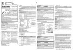
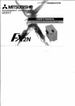
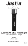
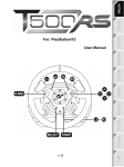
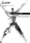
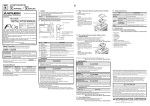
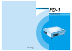
Side
B
JAPANESE
Side
ENGLISH
A
B
FX-232AWC-H
USER'S MANUAL
Unit : mm (inches)
25(0.99)
80(3.15)
RS-422
Connector
(D-SUB
25Pin
female)
I
POWER
FX
(RS422)
Manual Number
JY997D12601
Revision
G
Date
April 2015
4. Connecting Procedure
1.2 External Dimensions and Part Names
CONPUTER
(RS232C)
Side
60(2.37)
JY997D12601G
FX-232AWC-H
POWER Lamp
(Green)
Hole of screw for
the connector
fixation
[M2.6 (metric
screw thread)]
RS-232C Conne ctor
(D-SUB 25Pin female)
MASS (Weight) : 0.1kg(0.22lbs)
This manual describes the part names, dimensions, mounting, and specifications
of the product. Before use, read this manual and the manuals of all relevant
products fully to acquire proficiency in handling and operating the product. Make
sure to learn all the product information, safety information, and precautions.
Store this manual in a safe place so that it can be taken out and read whenever
necessary. Always forward it to the end user.
Registration:
The company and product names described in this manual are registered
trademarks or the trademarks of their respective companies.
Effective April 2015
Specifications are subject to change without notice.
© 2004 Mitsubishi Electric Corporation
Safety Precaution (Read these precautions before use.)
and
.
Indicates that incorrect handling may cause hazardous
conditions, resulting in death or severe injury.
Indicates that incorrect handling may cause hazardous
conditions, resulting in medium or slight personal injury
or physical damage.
Depending on the circumstances, procedures indicated by
also cause severe injury.
It is important to follow all precautions for personal safety.
2. Specification
may
Associated Manuals
Manual name
Manual No.
Description
FX Series User’s
Manual - Data
Communication
Edition
JY997D16901
MODEL CODE:
09R715
Explains N:N network, Parallel
Link, Computer Link, NonProtocol communication by RS
and RS2 instructions/FX2N-232IF.
How to obtain manuals
For product manuals or documents, consult with the Mitsubishi Electric dealer
from who you purchased your product.
• Use the product within the generic environment specifications described in PLC
main unit manual (Hardware Edition).
Never use the product in areas with excessive dust, oily smoke, conductive dusts,
corrosive gas (salt air, Cl 2 , H 2 S, SO 2 , or NO 2 ), flammable gas, vibration or
impacts, or expose it to high temperature, condensation, or rain and wind.
If the product is used in such conditions, electric shock, fire, malfunctions,
deterioration or damage may occur.
• Please contact a certified electronic waste disposal company for the
environmentally safe recycling and disposal of your device.
POWER Lamp is lit.
POWER Lamp is not lit.
The DC5V power supply from PLC is not supplied.
Confirm the items below.
• Ensure that the FX-232AWC-H and the
PLC are connected with the specified cable.
• Confirm whether the power supply is supplied to the
PLC.
(POWER Lamp of PLC lights when the power supply
is correctly supplied to the PLC.)
• Confirm whether the DC5V power supply capacity of
PLC is sufficient.
The PLC supplies DC5V to the special function
blocks.
(The PLC will not operate when a configuration
that exceeds the DC5V capacity is used.
It will also be impossible to communicate normally.)
2.1 General Specifications
The general specifications are equivalent to the PLC main unit.
For general specifications, refer to the manual of the PLC main unit.
2.2 Electrical Specifications
120mA or less
Bidirectional between RS-422 and RS-232C
Baud Rate
115200 bits per second, maximum
(The baud rate is different in connected equipment.)
3. System Configuration
The system configuration according to the connected equipment can be found in the
manual of the PLC main unit, positioning unit, programmable cam switch, or peripheral
equipment.
Additionally, when using Non-Protocol communication with the standard built-in port of
the FX3G Series PLC, refer to the FX Series User's Manual - Data Communication
Edition.
Remark
Compliance with all relevant aspects of
the standard. (Radiated Emissions and
Mains Terminal Voltage Emissions)
EN61131-2:2007
Programmable controllers
Equipment requirements and tests
Compliance with all relevant aspects of
the standard. (Radiated electromagnetic
field, Fast transient burst, Electrostatic
discharge, Damped oscillatory wave,
Conducted RF, High-energy surge, and
Power frequency magnetic field)
EN61000-6-2:2005
Electromagnetic compatibility
-Generic standards Immunity for
industrial environments.
Compliance with all relevant aspects of
the standard. (RF immunity, Fast
transients, ESD, Conducted, Surges,
Power magnetic fields, Voltage dips and
Voltage interruptions)
Attention
• This product is designed for use in industrial applications.
Note
• Authorized Representative in the European Community:
Mitsubishi Electric Europe B.V.
Gothaer Str. 8, 40880 Ratingen, Germany
Contents
The DC5V power supply from PLC is normally
supplied. Check the following when it is not possible to
communicate.
• Check if the correct cable is connected between the
FX-232AWC-H and the personal computer.
• Confirm whether the selection of the communication
setting and the connected model is correctly set
referring to the manual of the software which is
installed on the personal computer.
• The product is a precision instrument. During transportation, avoid any impacts.
Failure to do so may cause failures in the product.
After transportation, verify the operations of the product.
Level Conversion
User's Manual (this manual)
State of POWER Lamp
TRANSPORT AND STORAGE
PRECAUTIONS
Current consumption
FX-232AWC-H type interface unit
2) Connector cover
When it is not possible to communicate between the PLC (The positioning units and
the programmable cam switch are included.) and the personal computer via the
FX-232AWC-H, check the following depending on the status of the POWER Lamp of
the FX-232AWC-H.
DISPOSAL
PRECAUTIONS
5V DC power is supplied from the internal power
supply of PLC
Included items
Electromagnetic Compatibility
Standards (EMC)
EN61000-6-4:2007
Electromagnetic compatibility
-Generic standards - Emission
standard
for Industrial environment
Notes for compliance to the EMC regulation.
It is necessary to install the FX-232AWC-H module in a shielded metal control panel.
For more details please contact the local Mitsubishi Electric sales site.
3)
4)
5. Troubleshooting
• Do not disassemble or modify the PLC.
Doing so may cause fire, equipment failures, or malfunctions.
* For repair, contact your local Mitsubishi Electric distributor.
• Since the FX-232AWC-H case is made of resin, do not drop it or exert strong
impact to it.
Doing so may cause damage.
Power
Product
4) Fixing 4)
Connected
The FX-232AWC-H is a RS-422/RS-232C converter to connect the FX series PLC
with a personal computer.
Verify that the following product and items are included in the package:
3)
4)
1. Outline
1.1 Incorporated Items
●Note Concerning the CE Marking●
The CE marking does not guarantee that an entire mechanical module produced in
accordance with the contents of the notification comply with the following standards.
Compliance to EMC standards of the entire mechanical module should be checked
by the user / manufacturer.
Standards with which this product complies
Type: Programmable Controller (Open Type Equipment)
Models: Products manufactured from July 1st, 2004.
4)
7) POWER Lamp
INSTALLATION
PRECAUTIONS
STARTUP AND
MAINTENANCE
PRECAUTIONS
This manual classifies the safety precautions into two categories:
The procedure for connecting to peripheral equipment is shown.
1) Power off the PLC.
2) Remove the connector cover of the FX-232AWC-H.
3) Connect the cables to the connectors of the FX-232AWC-H.
(For the selection of the cable, refer to the manual of the connected equipment
or peripheral equipment.)
4) Fix the connector of the FX-232AWC-H and the connected cable with the fixing
screws.
5) Power ON the PLC.
6) Power ON the Personal computer.
7) Make sure the POWER Lamp of the FX-232AWC-H is lit.
(The POWER Lamp of the FX-232AWC-H lights when the power supply is
normally supplied by the PLC)
8) When the FX-232AWC-H is not in use, reattach the connector cover to prevent
dust from entering.
This manual confers no industrial property rights or any rights of any other kind,
nor does it confer any patent licenses. Mitsubishi Electric Corporation cannot be
held responsible for any problems involving industrial property rights which may
occur as a result of using the contents noted in this manual.
Warranty
Mitsubishi will not be held liable for damage caused by factors found not to be
the cause of Mitsubishi; opportunity loss or lost profits caused by faults in the
Mitsubishi products; damage, secondary damage, accident compensation
caused by special factors unpredictable by Mitsubishi; damages to products
other than Mitsubishi products; and to other duties.
For safe use
• This product has been manufactured as a general-purpose part for general
industries, and has not been designed or manufactured to be incorporated in
a device or system used in purposes related to human life.
• Before using the product for special purposes such as nuclear power, electric
power, aerospace, medicine or passenger movement vehicles, consult with
Mitsubishi Electric.
• This product has been manufactured under strict quality control. However
when installing the product where major accidents or losses could occur if the
product fails, install appropriate backup or failsafe functions in the system.
HEAD OFFICE : TOKYO BUILDING, 2-7-3 MARUNOUCHI, CHIYODA-KU, TOKYO 100-8310, JAPAN