1
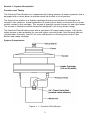
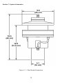
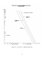
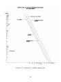
Filter Bucket Installation and Operation Manual Rev 06/01/2012 Part # ORS999004003 Table of Contents Section 1: System Description ………………………………………………………..…….. Section 2: System Installation ………………………………………………………….……. Section 3: System Operation ……………………………….……………..………………… Section 4: System Maintenance ………………………………………….…………….…… Section 5: System Troubleshooting ……………………………………….………………... Section 6: System Specifications ……………………………….……………………….….. Section 7: System Schematics ………………………………………………………………. Section 8: Replacement Parts List ………………….…………………….………………… Appendix A: Decontamination Procedures …………………………………………………. Warranty and Repair ……..………………………………………………..………………… 1 3 4 5 6 7 8 10 13 14 20 DOCUMENTATION CONVENTIONS This uses the following conventions to present information: An exclamation point icon indicates a WARNING of a situation or condition that could lead to personal injury or death. You should not proceed until you read and thoroughly understand the WARNING message. WARNING A raised hand icon indicates CAUTION information that relates to a situation or condition that could lead to equipment malfunction or damage. You should not proceed until you read and thoroughly understand the CAUTION message. CAUTION A note icon indicates NOTE information. Notes provide additional or supplementary information about an activity or concept. NOTE 2 Section 1: System Description Function and Theory The Geotech Filter Bucket is an independently floating passive oil-water separator that is equipped with a visual alarm to indicate when the bucket is full of product. The heart of the system is a floating cartridge that recovers product for storage in an integral 2-liter reservoir. Actual separation of product from water is carried out by a mesh screen located in the cartridge. This screen is specially treated to pass oil and repel water. The screen is therefore termed oleophilic/hydrophobic (oil loving /water hating). The Geotech Filter Bucket comes with a standard 100 mesh intake screen. A 60 mesh intake screen is also available for use with higher viscosity fluids. See Geotech Manual “Hydrocarbon Viscosity Test Kit” for more information on choosing the correct Filter Bucket and intake cartridge. System Components Figure 1-1 – Geotech Filter Bucket 3 Section 2: System Installation The Geotech Filter Bucket is placed in a sump, pond, or other body of water. It is easily deployed by holding the circumferential handle. The bucket and cartridge will float as shown in Figure 3-1. As it progressively fills, the bucket will sink into the water while the cartridge will remain at the water/product interface (Figure 3-3). When the bucket is full, remove it by its handle. Unscrew the cover and pour the product into a suitable receptacle. Clean any debris off the cartridge exterior if necessary. The cartridge surface is best cleaned with a soft brush and clean fuel. Care should be taken to remove debris without pushing it through the screen. Never clean with detergents, surfactants, or unknown solvents. If the Filter Bucket is left floating on water with little or no hydrocarbon present; the screen may eventually pass water and cause the bucket to sink. As a precaution against this possibility, tether the bucket by attaching a cord to the lifting handle. Attach the other end of the cord to the edge of the well or pond. 4 Section 3: System Operation When properly deployed, and before product has accumulated in the reservoir, the Filter Bucket should sit in the water as shown in Figure 3-1. As product passes through the cartridge, it falls into one of the two hoses and is gravity fed through the bucket wall and through a small check valve. When the cover of the bucket is removed, product can be seen flowing into the bucket. The rate of flow into the Filter Bucket is dependent upon the viscosity of the product and the thickness of the slick (See Section 6 - System Specifications). As product accumulates in the reservoir, the Filter Bucket will ride lower in the water as shown in Figure 3-3. At the same time, the product level indicator shaft will be extended through the top of the bucket. The Filter Bucket is designed so that the reservoir will cease taking on product just as the cartridge contacts the bucket handle. 5 Section 4: System Maintenance Although the separator screen has been designed to provide maximum surface area, build-up of debris will reduce the rate of hydrocarbon recovery. In most well sites, debris clogging is a minor problem because the hydrocarbon has already been filtered somewhat in moving through the earth. On settling ponds, where industrial waste oil must be recovered, screen clogging is potentially a more serious concern. Cleaning the Intake Screen and Filter Bucket The Geotech Filter Bucket will come with a floating cartridge containing a 100 or 60 mesh intake screen. When required, gently clean the screen with WD40 or kerosene, using a soft, bristle brush, to remove emulsified product, bio growth or other debris. Take care to avoid damaging the screen intake. Using warm soapy water, clean all debris and bio growth from the interior and exterior of the Filter Bucket. Rinse the cartridge assembly and bucket with clean water. Make sure the intake cartridge is completely dry before reconditioning the intake screen. Conditioning the Intake Screen Prior to initial deployment, and after every cleaning, the intake screen must be conditioned (or primed) with diesel fuel or other similar hydrocarbon. Use a soft, bristle brush to saturate the screen portion of the intake thoroughly. The optimum fluid would be to use the hydrocarbon to be recovered. Take care to avoid damaging the screen intake. 6 Section 5: System Troubleshooting If the Filter Bucket fails to perform properly, check for the following: Visually inspect the Filter Bucket for damage, such as loose fittings, cut hose, or cracks or splits in the reservoir. Verify that the intake screen is not clogged and can move up and down freely. Use the cleaning procedure in Section 4 if needed. Verify that there are no perforations to the screen. Check for clogging in the two hoses. Verify if the hydrocarbon can be “absorbed” with the type of mesh cartridge you are using (see User Manual “Hydrocarbon Viscosity Test Kit”. Section 8 contains a list of all serviceable parts. Also, technical support is available by contacting Geotech Environmental Equipment at 1-800-833-5978 or (303) 320-4764. 7 Section 6: System Specifications Dimensions Height: Diamter: Weight: Capacity: 16” (41 cm) 10” (25 cm) 7 lbs. (3.2 kg) .53 gallons (2 liters) Materials Body: Hose: Check valve: Cartridge: Polyethylene Polyethylene PTFE 100 mesh oleophilic/hydrophobic (blue) 60 mesh oleophilic/hydrophobic (green) System Limitations As with all systems, the Filter Bucket is limited by its components. These restrictions are classified into water product type recovered. Water Parameters The water parameters are classified into physical, chemical, and debris divisions. Physical State The physical bucket is designed as a surface follower to minimize its heave and pitch. When the water is rough due to current or wind conditions, the effect may reduce the ability of the cartridge to repel water. Under certain conditions, the cartridge will pass water. The slight density difference between product and water is inconsequential for the buoy flotation. If the unit is used exclusively in sea water, certain parts may eventually require replacement due to salt water corrosion. Chemical State Detergent or surfactant concentrations greater than 100 ppm (grams/liter) may cause the cartridge to pass water. Also, if the Filter Bucket is placed in an area with no product to “wet” the screen, a natural biological film will coat the screen and reduce its ability to repel water. Since this biological build-up (or fouling) is accelerated by warm temperatures, the cartridge will pass water more easily during the summer or in tropical environments. In general, oil/water emulsions will pass through the cartridge screen, and the extent of this problem is related to the relative amounts of product and water present. The oil/water interface always has both emulsion types present as well as high concentrations of surfactant. Whenever the Filter Bucket is deployed in thin layers of product, some water may pass through the cartridge. 8 Debris Presence of debris at the oil/water interface may reduce the product flow rate. Most debris accumulates on the mesh when a large volume of product enters the cartridge. Debris is easily removed when cleaning the cartridge. Often, the unit may be gently pulled up and down in its site area to remove some of the accumulated debris. Product Type Recovered The Filter Bucket will recover any non-polar liquid with a density less than water. This leaves out such dense materials as chloroform, carbon disulfide, carbon tetra-chloride and Freon. Certain materials will dissolve the housing and cartridge seals, but the unit may be used in an emergency or if concentrations of such materials are low. These materials are usually aromatics: common ones are benzene, xylene, toluene and styrene monomer. Materials that can readily be recovered include gasoline, kerosene, oils, hexanes, heptanes, octanes, petroleum, napthas, pentanes, or mixtures of the above. 9 Section 7: System Schematics Figure 7-1 – Filter Bucket Dimensions 10 Figure 7-2 – Time to Fill – 100 Mesh (Light Oil) 11 Figure 7-3 – Time to Fill – 60 Mesh (Heavy Oil) 12 Section 8: Replacement Parts List Parts Description Parts List SCREW,LID,CLOSURE ASSY CHECK VALVE,FILTER BUCKET HOSE,PVC FUEL,3/8"OD,1/16"WALL BALL,TFE,1/4" 2040005 00355 PPP001058 10097 ASSY,CARTRIDGE,100 MESH ASSY,CARTRIDGE,60 MESH MANUAL,TEST KIT,HYDROCARBON VISCOSITY TEST KIT,HYDROCARBON VISCOSITY MEDIUM OIL 2040002 2040003 26030020 86020001 MANUAL,FILTER BUCKET ORS999004003 13 Appendix A: Decontamination Procedures Some common decontamination solutions are listed below along with the contaminants they are effective against: Solution Effective Against Water Short-chain hydrocarbons, inorganic compounds, salts, some organic acids, other polar compounds. Basic (caustic or alkaline) compounds, amines, hydrazines. Acidic compounds, phenols thiols, some nitro- and sulfonic compounds. Non-polar compounds (such as some organic compounds) Dilute Acids Dilute Bases Organic solvents The use of organic solvents is not recommended because: 1) 2) organic solvents can permeate and/or degrade protective clothing and they are generally toxic and may result in unnecessary employee exposure to hazardous chemicals. When in doubt, use a dish washing liquid detergent. As a decontamination solution, it is readily available, is the safest of all the above, and is usually strong enough if used generously. The use of steam can also be effective for decontamination. A water-lazer (pressurized water) is exceptionally valuable. The following substances are noted for their particular efficiency in removing certain contaminants or for decontaminating certain types of equipment. Solution Effective Against Penetone PCB Contamination (since penetone may also remove paint, it is a good idea to spot-test before use) Liquinox Contaminated pumps Ivory liquid Oils Diluted HTH Cyanides Radiac Low level radioactivity Isopropanol Biological agents (should not be used on rubber products since it will break down rubber) Hexane Certain types of lab or sampling equipment (use of hexane is discouraged due to its flammability and toxicity) Zep General purpose cleaning Alconox General purpose cleaning 14 Decontamination Solutions to Avoid Some decontamination solutions should be avoided because of their toxicity, flammability, or harmful effects to the environment. Halogenated hydrocarbons, such as carbon tetrachloride, should not be used because of their toxicity, possible incompatibility, and some because of their flammability. Organic decontamination solutions should not be used on Personal Protective Equipment (PPE) because they may degrade the rubber or other materials comprising the PPE. Mercurials are sometimes used for sterilization. They should be avoided because of their toxicity. Chemical leaching, polymerization, and halogen stripping should all be avoided because of possible complications during decontamination. Sand-blasting, a method of physical removal, should be avoided because the sand used on the contaminated object usually needs to be disposed of as hazardous waste, a very costly proposition. Also, sand-blasting exposes personnel to silica, a carcinogen. Freon is known to be particularly effective for the cleansing of PCB's but its effect on the ozone layer is extremely harmful. Its use is discouraged. Strong acids or bases should not be used when cleaning metals and gaskets or tools or other equipment because of the possibility of corrosion. Disposal of Decontamination Solutions and Waste Water All solutions and water used for decontamination must be collected. If lab analysis indicates that the water and/or solutions exceed allowable contamination levels, they must be treated as hazardous waste. Alternatively, the solutions and water may be treated onsite to lower the contamination levels and render them non hazardous. Containers such as 55 gallon (208 liter) drums should be available for storage of wastes. Spent decontamination solutions can be collected by using heavy-duty plastic sheets, visqueen sheets, kiddie pools, or if needed, a larger containment basin. The decontamination of equipment must be performed on the sheets or in the basins. They could be placed on a slight angle so that the spent decontamination solutions drain into a collection basin or drum. Recommended Supplies for Decontamination of Personnel, Clothing and Equipment The list below contains recommendations for supplies which would be on hand for the decontamination of personnel, clothing and equipment. Depending on the site activities, not all of these items may be needed. Alternatively, some additional items not listed here may be required. Drop cloths of plastic or other suitable material, such as visqueen, for heavily contaminated equipment. 15 Disposal collection containers, such as drums or suitably lined trash cans for disposable clothing and heavily contaminated personal protective clothing or equipment to be discarded. Lined box with adsorbent for wiping or rinsing off gross contaminants and liquid contaminants. Wash tubs of sufficient size to enable workers to place booted foot in and wash off contaminants (without a drain or with a drain connected to a collection tank or appropriate treatment system). Rinse tubs of sufficient size to enable workers to place booted foot in and wash off contaminants (without a drain or with a drain connected to a collection tank or appropriate treatment system). Wash solutions selected to wash off and reduce the hazards associated with the contaminated wash and rinse solutions. Rinse solution (usually water) to remove contaminants and contaminated wash solutions. Long-handled, soft-bristled brushes to help wash and rinse off contaminants. Lockers and cabinets for storage of decontaminated clothing and equipment. Storage containers for contaminated wash and rinse solutions. Plastic sheeting, sealed pads with drains, or other appropriate method for containing and collecting contaminated wash and rinse water spilled during decontamination. Shower facilities for full body wash or at a minimum, personal wash sinks (with drains connected to a collection tank or appropriate treatment system). Soap or wash solution, wash cloths and towels. Clean clothing and personal item storage lockers and/or closets. 16 NOTES 17 NOTES 18 NOTES 19 The Warranty For a period of one (1) year from date of first sale, product is warranted to be free from defects in materials and workmanship. Geotech agrees to repair or replace, at Geotech’s option, the portion proving defective, or at our option to refund the purchase price thereof. Geotech will have no warranty obligation if the product is subjected to abnormal operating conditions, accident, abuse, misuse, unauthorized modification, alteration, repair, or replacement of wear parts. User assumes all other risk, if any, including the risk of injury, loss, or damage, direct or consequential, arising out of the use, misuse, or inability to use this product. User agrees to use, maintain and install product in accordance with recommendations and instructions. User is responsible for transportation charges connected to the repair or replacement of product under this warranty. Equipment Return Policy A Return Material Authorization number (RMA #) is required prior to return of any equipment to our facilities, please call our 800 number for appropriate location. An RMA # will be issued upon receipt of your request to return equipment, which should include reasons for the return. Your return shipment to us must have this RMA # clearly marked on the outside of the package. Proof of date of purchase is required for processing of all warranty requests. This policy applies to both equipment sales and repair orders. FOR A RETURN MATERIAL AUTHORIZATION, PLEASE CALL OUR SERVICE DEPARTMENT AT 1-800-833-7958. Model Number: ________________ Serial Number: ________________ Date of Purchase: ________________ Equipment Decontamination Prior to return, all equipment must be thoroughly cleaned and decontaminated. Please make note on RMA form, the use of equipment, contaminants equipment was exposed to, and decontamination solutions/methods used. Geotech reserves the right to refuse any equipment not properly decontaminated. Geotech may also choose to decontaminate the equipment for a fee, which will be applied to the repair order invoice. 20 Geotech Environmental Equipment, Inc. 2650 East 40th Avenue Denver, Colorado 80205 (303) 320-4764 ● (800) 833-7958 ● FAX (303) 322-7242 email: [email protected] website: www.geotechenv.com