1
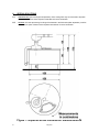
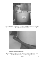
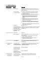
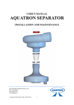
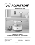
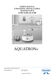
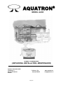
AQUATRON
®
MODEL 4x300
USER’S MANUAL
(UNPACKING, INSTALLATION, MAINTENANCE)
© Aquatron International
Aquatron International AB
Lisselberga 1
SE-725 93 Vasteras
Sweden
Teléfono / Fax:
+46 (0)21-560 20
May 2007
www.aquatron.se
[email protected]
Table of contents
Item
Page
2
Table of contents, table of pictures
1
Introduction
3
2
Unpackning
4
3
Preparations
4
4
4.1
4.2
4.3
4.4
4.5
4.6
Installation of the Aquatron system
Arrangement of the Bio Chamber
Installing the Separator
Pipe installation WC to Separator
Fluid outlet pipe installation
Installation of ventilation in the Bio Chamber
Flushing test
4
4
4
5
5
5
5
5
5.1
5.2
Composting
Startup
Vermi composting
5
5
5
6
6.1
6.2
Special solutions
Urine diversion
UV Units
6
6
6
7
7.1
7.2
7.3
7.4
7.5
7.6
Maintenance instructions for the Aquatron 4x300 models
The monitoring of an Aquatron system in use
Separator
Maintenance and drainage of the Bio Chamber
Composting
Vermi composting
Emptying a Bio Chamber section
10
10
10
10
10
10
10
8
8.1
8.2
8.3
8.4
8.5
8.6
8.7
Error Checking
Wet bio-bed
Odour in the room
Odour when windy
Stoppage in the Separator
Stoppage in the fluid outlet of the Separator
Stoppage in the fluid outlet of the system
Flies in the Bio Chamber
11
11
11
11
11
11
12
12
Table of pictures
Picture:
1
2
3
4
5
6
7
2
Aquatron 4x300 installation measurements
Separator installation
Connecting Separator and inlet pipe in coupler double socket
Angled double socket for inlet pipes longer than 1 metre
Some examples of horizontal pipe bends
Fluid outlet from Aquatron 4x300 system
showing the 4” vertical connection pipe
Connecting the Bio Chamber drain to
the pipe from the fluid outlet of the Aquatron Separator
May 2007
Page
6
7
7
8
8
9
9
1.
INTRODUCTION
IMPORTANT!
For optimal functionality it is very important that this installation manual
and the maintenance instructions are being followed closely. In case of
problems please contact the main supplier.
This is how it works – the solution is given by nature itself!
The liquid is flushed to a separator where urine and water is separated from faeces and paper. The
liquid will then pass through an Ultra Violet unit and may thereafter be infiltrated into the ground or
into a suitable receptacle. The solid waste is being composted in a Bio Chamber. If so wished,
composting worms may be added in order to accelerate the composting process.
1.
Aquatron uses standard Water Closets (flushing volume 3-6 litres) or special models where the urine is
mechanically diverted from the flushing water and the solid waste in the bowl itself.
2.
When the toilet is flushed, the contents of the bowl are transported to the Aquatron Separator where
approx. 98% of the liquid fraction is separated by using the momentum of the flushing water, centrifugal
force and gravity. The Aquatron Separator needs no moving parts.
3.
The solid waste (paper and faeces) falls down into the Bio Chamber where it is composted by bacteria
and, if desired, by worms. If using worms, the volume of the solid waste will be reduced by approx.
90%. The need for emptying and handling the waste is therefore reduced to a minimum. Optionally,
after installing an Aquatron System, some 250-300 worms are placed into the Bio Chamber. The
number of worms needed to maintain the composting process will be adjusted automatically by nature.
Optimal temperature for the composting is 12-25 degrees Celsius, a temperature level recommended
for year-round inhabited homes. Freezing will kill the worms. The composting process is free from odour
and flies because the Bio Chamber is ventilated and the small amount of liquid following the paper
down into the Bio Chamber is removed by a drain at the base of the Bio Chamber. When the Aquatron
90 and 400 models are emptied, the refuse must be composted to soil in the garden together with the
normal garden and kitchen waste. However, the models 4x100, 4x200 and 4x300, require no further
composting.
4.
The liquid proceeds to the UV unit where it is exposed to Ultra Violet light which kills bacteria and
viruses. The liquid may then be treated as Grey Water (bath, dish washing and laundry water) which
means that the toilet wastewater may be infiltrated into the ground or into a suitable receptacle. Since
the liquid fraction is separated from the solid waste, Aquatron Systems are not sensitive to peak load
usage.
Congratulations to your decision to buy the biological toilet system Aquatron!
Our experiences from many satisfied customers during more than 20 years is
that a correctly installed and properly maintained Aquatron system will serve
you and your guests well for many years to come.
Henry Steffensen
Managing Director,
Aquatron International,
Amberes AB
May 2007
3
2.
UNPACKNING
The following parts are packed into the Bio Chamber: Separator, hose clip to fix the Separator parts
together, Wire-ring, a branch to be attached to the Bio Chamber outlet, connection pipes between the
Separator outlet and branch, 90o Coupler double bend socket connecting the Separator and branch, turning
pole, a shovel for the emptying of compost and a ventilation fan. For pitch changes of the 110 mm inlet pipe,
a special angled coupler double socket is provided. For height adjustments of the separator, a triangular tray
with adjusting knobs is provided.
3.
PREPARATIONS
To install the AQUATRON toilet system you will need the following material in addition to the WC.
Components marked with an asterisk (*) are included in the shipment. Other items are to be purchased
locally if needed.
PIPES:
WC – Separator
4" Bend x 90º to WC
4” Coupler double sockets
4” Angled coupler double socket (*)
4” Pipes
Amount depending on number of
Water Closets to be connected
Amount depending on installation
For 4 % change of inlet pipe pitch
Amount depending on installation
Separator – Grey Water
sewage
4” Connecting pipes, 2 items (*)
For the fluid outlet of the separator,
- for vertical connection, 75 cm,
- for horizontal connection, 80 cm
4” Coupler double sockets, 2 items (*) For connections
4” Coupler double socket 90o bend,
2 items (*)
4” Coupler single socket 90o bend (*)
T-branch 110 mm / 50 mm socket (*) Connecting the Bio Chamber drain
2” Coupler single socket 90o bend (*) Single socket for Bio Chamber drain
MISCELLANEOUS:
(purchase separately)
Bark grinds
Platform (*)
Ventilation fan, AC 230 V (*)
100 mm ventilation pipes
4.
INSTALLATION OF THE AQUATRON SYSTEM
4.1
Arrangement of the Bio Chamber
4.1.1
4.1.2
4.2
4.2.1
4.2.2
4.2.3
4
100 litres (2 bags at 50 litres)
For the Bio Chamber
For the 100 mm ventilation channel
For the Bio Chamber ventilation
Position the platform firmly and horizontally, then place the Bio Chamber steadily on the platform.
For measurements see Figure 1.
The Aquatron system should be installed in a frost free compartment:
- optimal composting temperature is minimum 12° C (55° F);
- at ermin composting a temperature above 15° C (60° F) is recommended;
- if necessary, insulate the compartment and install a thermostat controlled electric heater.
Installing the Separator
Put together the upper and lower parts of the Separator unless they are already assembled. Check
that the Wire-ring is fully pushed down into the Separator neck and that the wires are not crossed.
The upper part of the Separator (Cyclone) should rest upon the Wire-ring. Tighten the hose clip just
as much as needed to keep the upper and lower parts of the Separator together. There must be no
space between the Cyclone and the Wire-ring, see Figure 2.
Place the triangular height adjustment tray on top of the Bio Chamber. Position the separator on top
of the tray and with the separator fluid outlet facing towards the perimeter of the Bio Chamber. Turn
the inlet of the Cyclone towards the pipe coming from the Water Closets. Check that the Cyclone
rests firmly on the Wire-ring and tighten the hose clip.
The Separator must be installed in a vertical position, see Figure 2.
May 2007
4.3
4.3.1
Pipe installation WC to Separator
Use 4” pipes between WC and Separator.
NOTE: Only WC should be connected to the inlet of the Aquatron Separator.
Separate pipes should be used for sewage from bath, kitchen, laundry etc. If
these pipes are to be connected, it should be done after the Aquatron system.
4.3.2
4.3.3
4.3.4
4.4
4.4.1
4.4.2
4.4.3
4.5
The Separator should be connected to a 4” double socket. NOTE: The Separator must be horizontal
and its vertical line (see Figure 2) perpendicular to the Bio Chamber. The inlet pipe must be fully
inserted into the socket, see Figure 3.
The horizontal distance between the WC and the Separator must be minimum 1 metre and that last
metre (closest to Separator) should be pitched at 5% (5 cm), see Figure 4. At further distances the
earlier part of the pipe should have a 1% horizontal slope, or as national standards. If needed, use
the special 4 % angled coupler double socket in order to achieve the pitch transition, see Figure 4.
(NOTE: Turn the colour mark of the angled coupler double socket downwards). Furthermore, check
that the inclination of the inlet pipe is smooth and that there are no depressions where fluid waste
may gather.
If horizontal bends are needed on the Separator inlet pipe, see Figure 5.
Fluid outlet pipe installation
For the pipes between the fluid outlet of the separator and the Grey Water sewage, there are two 4”
connecting pipes included in the delivery. The 75 cm pipe is for the vertical connection and is
connected to the horizontal connection pipe (length 80 cm) by the 90 degree bent double coupler
socket see Figure 6. To this connection pipe is also connected the drain outlet from the Bio Chamber
(2” diameter) by the 2” Coupler single socket 90o bend and a branch. See figure 7.
The outlet should be firmly attached to the supporting Aquatron 4x300 platform.
One 110 mm diameter Water Seal must be installed before the connection to the regular sewer in
order to prevent odours from the sewer system to enter the toilet/composting system.
Installation of ventilation in the Bio Chamber
The ventilation fan should be connected to the 100 mm attachment on top of the Bio Chamber and further to
a separate vent channel. The ventilation fan should be connected to a grounded AC 230 V electrical outlet.
NOTE! The ventilation must have a separate vent pipe extending over the roof and
must not be connected to the other sewer ventilation of the house, as this may
cause problems with odour and flies.
4.6
Flushing test
Ask someone to flush the WC with water only and check how much water is entering into the Bio Chamber.
If correctly installed, when flushing with water only, a maximum of 0.5 decilitres should go that way. If too
much water enters into the Bio Chamber there are two explanations:
4.6.1 If the water enters the Bio Chamber at the beginning of the flushing the velocity of the incoming
fluid is too high and the pitch is too large – decrease the pitch of the inlet pipe.
4.6.2 If the water enters the Bio Chamber at the end of the flushing the velocity of the incoming fluid is too
low and the pitch is too small – increase the pitch of the inlet pipe.
5.
COMPOSTING
5.1
Start up
Drainage of the Bio Chamber: Spread a 4-6 centimetre course bark grinds layer (NOTE: Not peat moss!)
into each composting compartment of the Bio Chamber. The bark grinds should be evenly spread at the
bottom of each compartment. Add some compost from the garden in order to insert micro-organisms. By this
the composting process will get a more rapid start.
5.2
Vermi composting
See Item 7.5.
May 2007
5
6.
SPECIAL SOLUTIONS
6.1
Urine diversion (Urine sorting/Urine separation): Urine sorting WCs may be connected to Aquatron
toilet systems. Please contact Aquatron International for more information.
6.2
UV Units: UV Units (accessory) for killing of the bacteria in the fluid outlet (after separation) could be
installed as an option. Please contact Aquatron International for more information.
Figure 1: Aquatron 4x300 installation measurements
6
May 2007
Figure 2: Separator installation
Figure 3: Connecting Separator and inlet pipe in coupler
double socket
May 2007
7
The horizontal distance between the WC and the Separator must be
minimum 1 metre and that last metre (closest to Separator) should be
pitched at 5% (5 cm). At further distances the earlier part of the pipe should
have a 1% horizontal slope, or as national standards.
Figure 4: Angled double socket for inlet pipes longer than 1
metre
Figure 5: Some examples of horizontal pipe bends
8
May 2007
Figure 6: Fluid outlet from Aquatron 4x300 system showing the
4“ vertical connection pipe
Connection of 50 mm drain from the 4x300 Bio Chamber to the horizontal
pipe from the Aquatron Separator (coming from right) before the connction
to the Water Seal (direction towards left).
Figure 7: Connecting the Bio Chamber drain to the pipe from
the fluid outlet of the Aquatron Separator
May 2007
9
7.
MAINTENANCE INSTRUCTIONS FOR THE AQUATRON 4x300 MODELS
7.1
The monitoring of an Aquatron system in use
It is recommended that an Aquatron system in use should be inspected at two week intervals (approximately). By discovering possible disturbances at an early stage (and to correct them immediately),
corrections can be made more easily as compared to cases where a minor disturbance over time have “built”
up to a major functional disturbance. The Items 7.2 – 7.7 below give advice about checks and measures for
such regular inspections. In Item 8 a special Error Check List is also included.
7.2
Separator
On the top of the Separator is an inspection lid. Occasionally paper may get stuck in the Wire-ring. Open the
lid and push the paper down by using a stick or a small pole. Too soft paper may “felt” too soon and there is
then a risk that it may stick to the wires which may cause too much water to fall into the Bio Chamber. To
avoid this it is recommended that you switch to another type of toilet paper. Depending on water quality
(water containing e.g. high contents of Calcium or Iron) a coating may develop on the wires. If heavily
coated, remove the parts and clean them with a brush.
7.3
Maintenance and drainage of the Bio Chamber
Check regularly the drainage of the Bio Chamber and the consistency of the compost. Also check that the
paper in the Bio Chamber does not build up a pyramid which reaches up to the Separator since that might
cause a stoppage in the Separator. If so, tilt the pyramid with a suitable tool, alternatively turn the
composting chamber slightly or switch to the next composting compartment. In the Bio Chamber there must
be a 4-6 cm layer of bark grinds evenly spread at the bottom. Add some compost from the garden in order to
insert micro-organisms. By this the composting process will get a more rapid start. It is important to use
coarse bark grinds NOTE: Not peat moss. If it is too smooth it may block the drainage grid which will cause a
wet compost. Suitable material is bark from pine or similar which may be acquired from garden shops or
shops marketing composting products. After using the Aquatron for a couple of years the drainage layer may
have to be renewed.
7.4
Composting
A balance between Carbon and Nitrogen is required for an optimal compost. In a latrine compost the Carbon
comes mainly from the toilet paper and saw-dust (if inserted as sprinkling powder) while the Nitrogen is in
the faeces. In the Aquatron systems a good balance between Carbon/Nitrogen is achieved when using
normal amounts of toilet paper. If the compost, having a correctly installed Separator, is still wet; the reason
might be too little Carbon. Then sprinkle some saw-dust over the compost.
7.5
Vermi composting
To accelerate the composting process and to effectively reduce the volume (reduction with approx. 90% of
the original volume), earthworms may be added (Eisenia Foetida, also called Dung Worm or Red Wiggler; or
an equivalent specimen). The worms should be added after a couple of weeks of usage.Compost worms can
normally be bought in gardening shops or in stores selling ecological products and equipments. The worms
may also be found in garden compost heaps. The vermi composting process works best at temperatures
between +12 and 25° C. In year-round living a temperature above +15° C is recommended in the room
where the Bio Chamber is installed. At temperatures below +10° C the composting process and the activities
of the worms is slowing down and their “food supply” will last longer which may be an advantage in summer
houses which are inhabited for a longer period of time.
After having switched to a new composting compartment the worms will remain in the previous filled
compartment until it is fully composted. Then the worms will migrate to the active composting compartment
in their seeking for “fresh food”.
The Bio Chamber must be installed in a frost free area for the survival of the
compost worms!
7.6
Emptying a Bio Chamber section
When the first used composting compartment reaches the emptying hole, remove the compost using a small
shovel but leave a layer of approx. 5 centimetres thickness. This way you will leave the drainage layer intact
(unless the layer has to be renewed). If the refuse has not become fully composted into soil, further
composting might be needed.
10
May 2007
8.
ERROR CHECKLIST
TYPE OF ERROR
CAUSE
MEASURE
8.1 Wet bio-bed
- Bad drainage
Check that the drainage holes are not blocked and that
the drainage layer is in accordance with the manual, see
Items 5.1 and 7.3.
- Too much water
in the Bio Chamber
A: Check that the Separator was installed horizontally
and that its vertical line is perpendicular to the Bio
Chamber, see Figure 2.
B: Check that the Wire-ring is positioned correctly and
that the wires do not stick to the inside of the the
Separator neck. The wires should be slightly bent
towards the middle of the Separator neck, see
Figure 2.
C: Check that the cyclone is fully pushed down into the
Separator neck and it rests firmly on the Wire-ring.
See Item 4.2.1 and Figure 2.
D: Check pitch of the inlet pipe. At too large pitch, fluid
enters the Bio Chamber at beginning of the flushing;
at
too low pitch, fluid enters the Bio Chamber at the end
of the flushing. See Item 4.6.
E: Repair the WC.
- Leaking WC
- When flushing there is Check the pitching of the inlet pipe. It must have a smooth
a surge or after flushing slope and no depressions where fluid waste may gather,
there is still a small
see Item 4.3.3.
string of fluid or batches
of fluid entering the
Separator
8.2 Odour in the room - Wet bio-bed
- Wrong ventilation
See above.
A: The ventilation pipe is too short, it does not extend
over the roof.
B: The ventilation is coupled together with the other
sewer ventilation of the house.
C: Check the waterseal to assure that no odour is
coming from the sewer system.
8.3 Odour when windy - Air is pressed into
the ventilation
The ventilation pipe does not extend high enough above
roof. It must be lengthened. Mount a vane on the
ventilation pipe.
8.4 Stoppage in the
Separator
- A too high pyramid
of paper has been built
up in the Bio Chamber
Tilt the pyramid with a suitable tool, alternatively turn the
composting chamber slightly or switch to the next
compartment if needed.
- The wires in the Wirering of the Separator
are bent or crossed
Straighten the wires.
- The inlet of the
Separator is not fully
inserted into the socket
Adjust, see Figure 8.
- The flushing water is
entering the Separator
at too high speed
The pipe between WC and Separator has a too
large inclination. See Items 4.3.2, 4.3.3 and 4.6.
8.5 Stoppage in the
fluid outlet of
the Separator
May 2007
11
8.6 Stoppage in the
fluid outlet of the
system
- Sediments or foreign
objects in the fluid
outlet
Check that the fluid is not stopped in the waterseal in the
fluid outlet of the system. If necessary clean the waterseal
from sediments and foreign objects.
8.7 Flies in the
Bio Chamber
- Wet bio-bed
See Item 8.1 and 8.2 above.
Spray the inside of the Bio Chamber with an appropriate
insecticide.
12
May 2007