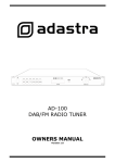
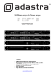
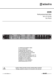
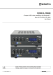
1
1U Mixer-amps & Slave amps A121 A251 S121 S251 Mixer-amp + USB/FM 120W Mixer-amp + USB/FM 250W Slave amp 120W Slave amp 250W 952.904 952.906 952.908 952.911 User Manual Features: 2 Mixer-amp models and 2 Slave versions Transformer coupled output for 100V or 4-16Ω operation USB/FM audio player on mixer-amp models Compact 1U rack-mount format Dual fan-cooled High efficiency toroidal transformers 32V phantom power for Mic 1 (switchable) www.avsl-adastra.com Introduction: Thank you for choosing this Adastra 1U amplifier This product has been designed to offer reliable, high quality amplification for various installation and PA applications. In order to gain the best results from this equipment and avoid damage through misuse, please read and follow these instructions and retain for future reference. Warning: To prevent the risk of fire or electric shock, do not expose any of the components to rain or moisture. If liquids are spilled on the surface, stop using immediately, allow unit to dry out and have checked by qualified personnel before further use. Avoid impact, extreme pressure or heavy vibration to the unit. There are no user serviceable parts inside the amplifier – refer all servicing to qualified service personnel. Safety Check that the mains lead is in good condition and that the supply voltage selector switch matches the supply voltage. Ensure signal leads and speaker cable(s) are in good condition Do not use the USB connector as a general purpose power source or charger. Do not allow any foreign particles or liquids to enter the amplifier through the cooling vents Do not cover or obstruct cooling vents or fan grilles. Placement Keep out of direct sunlight and away from heat sources. Keep away from damp or dusty environments. When rack-mounting, secure firmly in place and avoid positioning heavy items directly on top of the unit Ensure adequate access to controls and connections and pay attention to cooling air-flow Cleaning Use a soft cloth with a neutral detergent to clean the housing as required Use a soft brush to clear debris from the cooling vents and connectors Do not use strong solvents for cleaning the unit. Front Panel 1. 2. 3. 4. 5. 6. Combo MIC1 input – Balanced XLR/6.3mm mic. input - channel MIC1 – Volume control for MIC channel 1 MIC2 – Volume control for MIC channel 2 LOW – Bass EQ control for MIC channels HIGH – Treble EQ control for MIC channels VOX – Auto voice-over control for MIC channels 7. 8. Cooling vents LINE1 – Volume control for Line input 1 9. LINE2 – Volume control for Line input 2 10. USB/FM/AUX – Volume control for USB/FM/AUX channel 11. 12. 13. 14. 15. 16. 17. 18. 19. LOW – Bass EQ control for LINE and USB/FM/AUX channels High – Treble EQ control for LINE and USB/FM/AUX channels MASTER – Main output volume control USB input for storage device LED power, level and limit indicators USB/FM display USB/FM transport and mode controls 3.5mm stereo jack for AUX input (channel 3) POWER – Mains On/Off switch Rear Panel 20. 21. 22. 23. 24. IEC mains inlet and integral fuse Voltage selector 110/240Vac Mono 6.3mm speaker jack outputs (4-16Ω only) 100V speaker output terminals Cooling Fans 25. 26. 27. 28. 29. FM antenna connection OUTPUT – 2 x RCA line output LINE1 + LINE2 – 2 x RCA line inputs MIC1 + MIC 2 – 2 x balanced 6.3mm jack MIC inputs Phantom power switch (32V) for MIC1 Connection The Adastra A-series mixer-amps and S-series slaves can drive EITHER 100V line OR 4-16Ω speakers. Both types of speaker should NOT be connected together to the same amplifier. 100V Line Speakers 100V line speakers must be connected using the “100V” and “COM” screw terminals (23) on the rear panel. All 100V line wiring should be run with double-insulated cable rated to the max current for the system. For example, in a 250W system @ 100Vmax, 250W/100V=2.5A, so the speaker cable should be rated to 2.5A minimum Each speaker must be connected in a parallel chain and the total wattage for all speakers should not exceed 90% of the amplifier’s rated output. Please see the diagram below to show an example arrangement. Cooling fans Low Impedance Speakers If standard low impedance (4Ω, 8Ω or 16Ω) speakers are being used, these should be connected to the 6.3mm output sockets on the rear panel using quality speaker jack leads. Both of these outputs are fed from the same amplifier section, which is mono. The minimum impedance of the total speaker load connected to either or both of these sockets must be no lower than 4Ω. The impedance is calculated using an inverse calculation as shown below. _________1________ Impedance Speaker 1 + _________1________ Impedance Speaker 2 = _________1________ Overall Impedance = _1_ 4Ω … therefore, for 2 speakers – each 8Ω impedance… _1_ 8Ω + _1_ 8Ω … so the overall impedance is 4Ω for both speakers connected in parallel. The diagram below gives an example of this… Inputs – Slave amplifiers The S121 and S251 slave amplifiers accept a LINE IN via 2 x RCA connectors at the rear and the same signal can be sent out to further amplifiers from the LINE OUT pair of RCA connectors. Since the amplifier is mono, all stereo inputs are summed together. Inputs – Mixer-amplifiers A microphone can be connected to MIC1 channel by either 6.3mm jack or XLR to the front panel combo input. If required, there is also a 6.3mm jack connection on the rear panel for MIC1 channel. A further microphone can be connected to MIC2 channel via a 6.3mm jack on the rear panel. For microphones which require phantom power, a switch on the rear panel can apply +32V phantom to MIC1 front combo and MIC1 rear jack inputs. * ENSURE THAT ONLY TRS JACK PLUGS ARE USED FOR MIC1 WHEN PHANTOM POWER IS SWITCHED IN Line inputs (e.g. CD, DVD, mp3 players) can be connected to LINE1 and LINE2 channels via pairs of RCA connectors on the rear panel. Alternatively, for the USB/FM/AUX channel, a stereo 3.5mm socket on the front panel can be used instead – ideal for portable mp3 players etc. There is also a USB type A connector on the front panel for playback of digital audio files stored on a USB pen. The overall mix can be connected to further amplifiers via the OUTPUT pair of RCA connectors. Operation With all volume levels and VOX control turned down, connect the amplifier to the mains supply (ensure correct supply voltage) using a suitable IEC lead (as supplied) and switch POWER on. HIGH and LOW EQ controls should be initially set to the vertical “12 o’clock” position. If microphones are being used, turn up the MASTER control approximately half way and gradually increase MIC1 rotary level control whilst speaking into the microphone until the required volume is reached. Repeat for MIC2 volume control. Adjust HIGH and LOW EQ controls to alter the overall bass and treble response of both microphones as needed. For any line level devices connected to line input channels, adjust the LINE1 and LINE2 level controls in the same way as for the microphone channels. Overall tone of the line inputs (including the USB/FM/AUX) can be adjusted via the HIGH and LOW controls. For the USB/FM/AUX channel, pressing MODE toggles between the USB device, FM tuner or AUX input as a sound source. Turning the USB/FM/AUX level control increases the level of the playback through the amplifier For the FM tuner, an initial channel search can be performed by pressing “CH –“ followed by “PLAY/PAUSE” . The USB/FM/AUX transport controls are as follows… • Control USB FM Tuner AUX Press & Hold PRE CH Previous track Search down Volume down • • NEXT PLAY CH+ PAUSE Next track Pause / Play / Track Time Search up Halt search No function FM channel/frequency USB Volume up Pause/Total No. tracks • MODE Toggle USB/FM/AUX The player status is indicated by a small backlit LCD screen to the immediate left of the transport buttons. For MIC channels priority, increasing the VOX control will cause the level of playback through the LINE or USB/FM/AUX channels will be reduced when speaking into MIC1 or MIC2. Adjust this control to achieve the required amount of “ducking” of the other channels when MIC channels are used. SPECIFICATIONS Model Power supply Output: RMS @ 4Ω Mic input front Mic inputs rear Line input front Line inputs rear Mic controls Line controls USB/FM/AUX player controls LED indicators Phantom power Line output Speaker outputs: 4Ω - 16Ω Speaker outputs: 100V line Dimensions Weight A121 A251 S121 Switchable 110/240Vac, 50/60Hz (IEC) 120W 250W 120W MIC1 combo connector (XLR/jack) N/A MIC1 & MIC2 6.3mm jacks N/A AUX stereo mini jack 3.5mm N/A LINE1 & LINE2 RCA (pairs) N/A MIC1 & MIC2 Levels, Low/High EQ, VOX N/A LINE1, LINE2, USB/FM/AUX Levels, Low/High N/A Play/pause, PRE (CH -), NEXT (CH +), MODE N/A On, -24/18/12/6/0dB, Limit 32V switchable (Mic 1) N/A RCA (L+R) with Master volume control 2 x 6.3mm jack (4 ohms min) Com/100V screw terminals 483 x 44 x 325mm (1U) 7.8kg 8.4kg 7.5kg S251 250W N/A N/A N/A N/A N/A N/A N/A 8.0kg Troubleshooting No power LED on control panel Power LED is on but no other LEDs and no output No output from condenser microphone Power light and output LEDs lighting but no output FM tuner drifts from programme channel USB player will not play audio from media Output is very loud or LIMIT LED is on constantly Output is working but at very low level Feedback (loud squealing or howling from mics) Amplifier is getting very hot Ensure IEC lead is in good condition and connected properly Ensure mains outlet voltage is same as voltage selector Check mains inlet fuse Ensure POWER switch is on Check input signals and condition of input connection leads Check MASTER, MIC or LINE controls are not turned fully down Turn down VOX control Ensure Phantom Power is switched on (turn Master down first) Check that condenser microphone is not plugged into MIC2 Check speaker leads are in good condition and connected properly Check speakers are working (test on another amp if available) Attach an FM antenna to the F connector on the rear panel Switch unit off and then on again (tuning may drift with temperature) Press CH- then PLAY/PAUSE to perform channel search + store Press PLAY on transport controls Check memory device is connected properly (remove and re-insert) Check file types – standard compressed digital audio files required Check memory device works on a PC or Mac for standard playback Check level of input signal is not too high Reduce channel volume and EQ settings Reduce MASTER level until LIMIT light stops flashing Ensure Hi-Z line level input(s) not connected via MIC1 or MIC2 Check input audio source level is not too low Increase channel volume and EQ settings if turned down Increase MASTER level Check for quiet recording of media files on USB Face microphone away from speakers and monitors Reduce channel volume and EQ settings Reduce MASTER level Make sure fans are working properly and not obstructed Ensure cooling vents are clear from debris and dust Check that 4Ω or 8Ω speakers are not connected to 100V terminals Ensure total 100V speaker wattage is not more than amplifier rating Ensure that 100V and 4Ω or 8Ω speakers are not both connected Ensure that total load across speaker jack outputs is not less than 4Ω Note: for further troubleshooting, refer equipment to qualified service personnel for testing © Adastra 2012