1
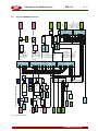
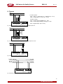
BIO - IAQ Sensor for Indoor Air Quality
Metal Oxide Indoor Air Quality (VOC) Sensor
User Manual
October, 2014
AUTOMATIKPRODUKTER
IAQ Indoor Air Quality Sensor
BIO 010
Oct. 14
1
Intended Use ........................................................................................................................................3
2
Functional Description .......................................................................................................................3
2.1
2.2
2.3
2.4
2.4.1
2.4.2
3
VOC Sensor ................................................................................................................................3
VOC Measurements ....................................................................................................................3
Temperature Measurement (option)............................................................................................4
Functions .....................................................................................................................................5
Sensor Function.....................................................................................................................5
Controller Function................................................................................................................6
Installation............................................................................................................................................7
3.1
Mounting Instructions ..................................................................................................................7
4
Electrical Connection ..........................................................................................................................7
5
ModBus ................................................................................................................................................8
5.1
5.2
5.3
5.4
5.5
5.6
5.7
General ........................................................................................................................................8
Physical Port ................................................................................................................................8
Time Response ...........................................................................................................................8
ModBus Functional Description ...................................................................................................9
Troubleshooting .........................................................................................................................10
ModBus Register Description ....................................................................................................11
Overview ModBus Functions .....................................................................................................13
6
Commissioning .................................................................................................................................14
7
Specifications ....................................................................................................................................15
8
Figures................................................................................................................................................16
9
Notes and General Information ........................................................................................................19
9.1
9.2
9.3
10
Installers’ Responsibilities .........................................................................................................19
Maintenance ..............................................................................................................................19
Limited Warranty .......................................................................................................................19
Part Disposal......................................................................................................................................19
2
AUTOMATIKPRODUKTER
IAQ Indoor Air Quality Sensor
BIO 010
Oct. 14
IAQ Indoor Air Quality (VOC) Sensor
1 Intended Use
The BIO IAQ air quality sensor with digital processing of the measuring values and temperature compensation
is used for measuring and controlling the air quality in indoor areas within environmental conditions specified in
the Technical Data.
The intended sites are all areas being directly connected to the public low voltage supply, e.g. residential,
commercial and industrial ranges as well as small enterprises (according to EN50 082).
The BIO IAQ sensor must not be used in potentially explosive atmospheres. The sensor must only be
employed in areas within the environmental conditions as specified in the Technical Data.
Electronics can be destroyed by static electricity. Therefore, do not touch the equipment without a
wrist strap connected to ground or without standing on a conductive floor (acc. to EN 61340-5-1).
2 Functional Description
2.1 VOC Sensor
The semi-conducting metal oxide sensor measures the electrical conductivity of the nanocrystalline metal oxide
coated on a heatable substrate. The typical operating temperature is between 300 and 400 °C. The doping of
the metal oxide with noble metals results in a positive sensibility to combustible gases like VOCs, carbon
monoxide and natural gas. The doping permits the adaptation to the demands of the measuring task. VOCs are
partially or totally burnt at the sensor surface by the oxygen of the metal oxide. The electrons released in the
semi-conductor by this process lead to an increase of the electrical conductivity. At the end of the combustion
process, the metal oxide returns to its initial state by incorporating oxygen from the air, with the conductivity
also adopting the initial value. The change of the conductivity is evaluated via the internal micro-controller and
output as a standard signal.
2.2
VOC Measurements
The VOC content in indoor areas is mainly determined by the persons present and their activities. See table 1.
When for example working with cleaning agents or when cooking, VOCs (Volatile Organic Compounds) are set
free, but also human respiration is a constant source of volatile metabolism products (VOCs). The air quality
sensor detects the increasing VOC level and calculates the proportional CO2 value. The VOC/CO2 correlation
was determined by taking measurements under real conditions. See diagram 1.
To this day, there aren’t any standard signals for the VOCs; therefore the IAQ air quality sensor reduces the
measured VOC values to CO2 equivalents with the unit ppm. This grants the compatibility to existing CO2
ventilation standards.
Each time the IAQ air quality sensor is switched on, it runs through a warm-up period of 20 minutes. During this
warm-up period there aren’t any measurements; the sensor outputs the signal of 80% of the measuring range.
After the warm-up period, the sensor interprets the currently read VOC value as zero-point, independently from
the actual concentration. An internal algorithm continuously updates the zero-point by taking the lowest
measured VOC value. Therefore the ambient air should be of low VOC content after the warm-up period. This
can be obtained by shortly venting when starting the measurements with the 80% signal.
If the sensor isn’t started at low VOC concentrations, it can take a couple of days until the internal algorithm
has updated the zero-point so far that effective measuring results are available.
The natural sensor drift and ageing is corrected by the implemented control algorithms.
3
AUTOMATIKPRODUKTER
IAQ Indoor Air Quality Sensor
Indoor Air
Contamination
Source
BIO 010
Typical Substances
Emission Source
VOCs
Oct. 14
Ventilation
Others
Acetone, Ethanol, Isoprene
CO2
Humidity
Nonanal, Decanal, α-Pinene
*Skin respiration &
transpiration
Humidity
*Flatus
Methane, Hydrogen
Human Being
*Cosmetics
Limonene, Eucalyptol
*Household Supplies Alcohols, Esters, Limonene
Unburnt Hydrocarbons
*Combustion
CO
(Engines,
Appliances, Tobacco CO2
Smoke)
Humidity
*Paints
Formaldehyde, Alkanes,
*Adhesives
Alcohols, Aldehydes,
*Building Material
*Solvents
Ketones, Siloxanes
*Furniture
*Carpets
*Office Equipment
*PVC
Toluene, Xylene, Decane
+Consumer Products
*Printers/Copiers,
Benzene, Styrene, Phenole
Computers
*Breath
demand
controlled
permanent
(5-10%)
Table 1 – Typical indoor air contaminants (VOC and others)
VOCs
CO2
Window
opened/closed
Odors
VOCs
0
CO2
1hr
2h
3h
4h
Diagram 1: Correlation CO2- VOC (records from a business meeting session)
2.3
Temperature Measurement (option)
The temperature measurement is done via an internal sensor. The signal is output as a linear 0 – 10 V signal.
A customer’s application with passive signal is possible as an option.
Additional heat sources in the flash-mounted box have an influence on the temperature
measurements and have therefore to be avoided.
4
AUTOMATIKPRODUKTER
IAQ Indoor Air Quality Sensor
2.4
BIO 010
Oct. 14
Functions
2.4.1
Sensor Function
The IAQ sensor shows the VOC value (0 – 4000 ppm or 0 – 2000 ppm) in form of a 0- 10 V signal at the analog
output AO1. The temperature (0 – 50 °C) is also available as a 0 – 10 V signal at the analog output AO2.
In ModBus operation, the VOC value is displayed at the read register 01 and the temperature value at the read
register 02.
The IAQ sensor offers a great number of options. The function can be defined according to the application via
the ModBus interface by means of the ModBus function diagram (fig. 5). The definition of the function can be
provided in the factory as well as on site by using the ModBus tool.
Option Setpoint Potentiometer
The temperature output can be adjusted by ± 3 °K.
Option Digital Output DO1
The digital output is activated in dependence of the programming via the following functions.
•
Depending on the VOC value via the internal switch threshold (threshold = write register 03)
•
Depending on the temperature value via the internal switch threshold (threshold = write register 03)
•
Switch threshold can be selected via internal potentiometer.
•
Via digital input 1 or 2.
•
Via the operation mode switch.
Option Digital Output DO2
Function is the same as for digital output DO1.
The digital output DO2 takes the place of the analog output AO2, meaning that with two digital outputs, there is
only one analog output available.
Option Status LED 1
The Status LED is activated in dependence of the programming via the following functions.
•
Via digital input 1 or 2.
•
Via the operation mode switch.
•
Via digital output 1 or 2.
•
ModBus command.
Option Status LED 2
•
Function the same as for Status LED 1
Option Operation Mode Switch
The switch activates the digital outputs (DO1/DO2) and/or the status LEDs (LED1/LED2) in dependence of the
programming.
Option IAQ Power
The IAQ Power Module offers a 230 VAC supply voltage for the IAQ sensor. A wet switch contact (230 V) is
available in addition. The switch contact is activated via the digital output DO1.
The IAQ Power Module is mounted in the in-wall box. See fig. 10 and 11.
5
AUTOMATIKPRODUKTER
IAQ Indoor Air Quality Sensor
2.4.2
BIO 010
Oct. 14
Controller Function
The standard control function described here can be changed via the ModBus interface by means of the
ModBus function diagram (paragraph 5.7).
Air quality control function
The controller outputs the control signal (AO1 / 0- 10V) within the defined control range of 700 to 1200 ppm in
dependence of the VOC concentration. The output signal is suppressed for all values below 700 ppm in order
to grant a dead band.
The green LED is on for “good air quality”, that means the measured VOC value is < 700 ppm.
The orange LED is on for „bad air quality“, meaning that the measured VOC value is > 700 ppm.
The control parameters are factory-set, but can be adjusted to the application via ModBus.
Temperature control function
The pre-set temperature of 21°C can be changed via the potentiometer by +/- 3°K.
When the function “heating” is selected and the temperature falls below the set value, the PID controller
delivers a signal at the analog output (AO2/ 0-10V) until the desired temperature is obtained and keeps this
temperature up. The function of the air quality control (AO1) is blocked when the temperature falls below the
set minimum temperature of 18°C.
When the measured temperature exceeds the set maximum temperature of 26°C (+ summer DIN increase),
the air quality control is forced to 100% (10 V at the output).
The control parameters are factory-set, but can be adjusted to the respective configuration via ModBus (see
point 5.6 and 5.7).
Fig. 1: Output signal VOC control
Option
Status LED
Option
Betriebsarten Schalter
Potentiometer
intern
IAQ
IAQ
IAQ
Option
Sollwert Potentiometer
Fig. 2: Views:
Sensor
Complete version
Internal potentiometer
6
AUTOMATIKPRODUKTER
IAQ Indoor Air Quality Sensor
BIO 010
Oct. 14
3 Installation
3.1 Mounting Instructions
When choosing the mounting site please pay attention to the following:
•
Do not mount the sensor next to doors, windows, air inlets and outlets.
•
Free air supply must be granted.
•
Vertical mounting (air inlet at the sensor down/up)
•
Avoid direct sunlight.
•
No heat sources around in case of temperature measurement.
60mm
Recommended mounting height is 1.0 m (3 feet) to 1.5 m (5 feet) above floor.
83,4mm
•
= 3mm
60mm
78,3mm
Fig. 3: Mounting IAQ Sensor
For IAQ-Power Module see also fig. 10 and 11
4
Electrical Connection
•
Installation of the electrical wiring should only be executed by a trained specialist according to the
connection diagram, without any power applied to conductors and according to the corresponding
regulations!
•
The connection is done via screw-type terminals with a section of 0.25 to 1.5 mm2.
•
The connection of the different applications is shown in the figures 7 to 11.
•
Avoid any influence of external interference by using shielded cables for the signal line, but do not
connect the shield.
•
For ModBus wiring we recommend using the cable Y(St)Y 2x2x0.8 LG, in line topology and without
any branch lines. Please consider in addition all regulations concerning the wiring of RS-485 field bus
wiring.
7
AUTOMATIKPRODUKTER
IAQ Indoor Air Quality Sensor
5
BIO 010
Oct. 14
ModBus
5.1
General
The ModBus protocol was developed for the data exchange between information processing units,
programmable logic controllers and other intelligent systems. A master computer communicates with maximum
247 connected devices via a serial data link of RS-485 standard. There is only one device (host, master) per
bus line determining the telegramming. The other devices (clients, slaves) only react on the request of the
master and are never allowed to send data on the bus line without request of the master device.
The data are transmitted in form of data telegrams. There are two possible formats within the ModBus protocol,
the ASCII and the RTU format. Only the RTU format is used and described in here.
The RTU telegram settings don’t include any tag delimiters.
The beginning and the end of data telegrams are realized by short stops.
The syntax is as follows:
Address
Command
Data
CRC16
The data are transmitted with binary code. The address and the command are 1 byte each. When requested
from the master, the data may contain for example address, order and the initial address and the number of
data to be retrieved.
The answer from the slave is structured in the same way. The data may contain, besides the address and the
order, for example the number of sent data bytes and the data.
CRC16 is a 2-bytes Cyclical Redundancy Check.
The end of the data telegram is recognized if there is an idle period of minimum 2 characters.
The slaves react to valid requests after a certain timeout after receipt of the last character by giving the
corresponding answer. The master then expects the start of the answer. If it doesn’t come, the master can
occupy the bus anew and give new commands. The slave answers after a silence of 3.5 characters at the
earliest. In case of transmission errors or not executable commands, the slave doesn’t answer or respond with
an error message (see troubleshooting).
5.2
Physical Port
The communication between master and slaves uses a serial data link of RS-485 standard.
The port settings are as follows:
9600 Baud,
5.3
1 Start Bit,
8 Data Bits,
Parity none,
1 Stop Bit
Time Response
Transmission telegram:
The master can start a data exchange. The master sends a data telegram to a slave containing:
•
Address of the slave
•
Function requested from the slave (order)
•
Data field (variable depending on the order)
• Control characters
The slave starts uploading a telegram after each idle period of 3.5 characters. If the first character is the slave’s
own address or the address 0 (all), it processes with the telegram. If there is a silence of 2 characters at least,
it considers the telegram finished and checks the CRC.
If the telegram is without errors, it executes the function and composes an answer.
8
AUTOMATIKPRODUKTER
IAQ Indoor Air Quality Sensor
BIO 010
Oct. 14
Answer telegram:
•
Address of the slaves
•
Executed function (order)
•
Data field (e.g. data length and data)
• Control characters
The answer is sent at the earliest after a silence of 3.5 characters after the end of the master’s telegram.
In case of an error, the slave waits for the end of the telegram and the period of 3.5 characters, and then
returns an error message.
The master awaits the answer of the slave or a timeout (see table) before starting a new exchange in order to
avoid complications resulting from mutual transmissions.
Data organization
The devices offer properties and states generally described here as objects. These objects can be asked
specifically as bit or byte ranges by the master and changed by it.
An input object can only be read.
An output object can be read or written.
ModBus functions
The following functions are available with the communication protocol ModBus:
•
The main functions granting the data exchange.
• The additional functions for the control and the diagnosis of the data exchange.
The table below indicates the functions managed here.
The functions “Read” and “Write” refer respectively to the action of the master.
Function
5.4
Description
Implemented
03
Reading of N output registers
Yes (max 32 reg.)
16
Writing of N output registers
Yes (max 22 reg.)
ModBus Functional Description
Function 03: Reading of N output registers
This function enables to read the output registers; these are the registers the master can read or write in the
slave.
This function enables to read the input registers; these are the registers the master only can read.
Example:
Reading of N registers; function 3
Request:
Slave address
1 - 254
Function
03
Start address
Number of words
CRC16
1 Byte
1 Byte
2 Bytes
2 Bytes
2 Bytes
Slave address
1 – 254
Function
03 or 04
Number of sent bytes
Data
CRC16
1 Byte
1 Byte
1 Byte
n Bytes
2 Bytes
Answer:
9
AUTOMATIKPRODUKTER
IAQ Indoor Air Quality Sensor
5.5
BIO 010
Oct. 14
Troubleshooting
If there is any parity, framing, overrun or CRC error during receipt of a telegram, the slave doesn’t accept and
answer it.
If the slave cannot execute the requested order, it sends an error message.
Format of an error message:
Slave address
1 - 254
1 Byte
Answer code:
Answer code
Error code
CRC16
1 Byte
1 Byte
2 Bytes
Order function code + 0x80 (the most significant bit is set to 1).
10
AUTOMATIKPRODUKTER
IAQ Indoor Air Quality Sensor
5.6
BIO 010
Oct. 14
ModBus Register Description
Register
0
1
2
3
4
5
6
7
8
9
10
11
12
13
14
15
16
17
18
19
20
21
22
23
24
25
26
27
28
29
30
31
Read register Request with command 0x03
Description
Range
Sensor type
(defined by product type)
Measured value VOC
0- max (defined in register 11)
Measured value Temperature 0- max (defined in register 12)
PID output value VOC
0-10000
PID output value Temp
-10000 to +10000
PID sign Temp
+1 = heat; -1 = cool
res
res
res
Potentiometer position
0-10000
Own MODBus address
1-255
Measuring range VOC
0-32767
Measuring range Temp.
0-32767 (50 with 1 decimal place)
Alarm threshold 1
0- max (defined in register 11 o 12)
Alarm threshold 2
0- max (defined in register 11 o 12)
Hysteresis 1
0- max (defined in register 11 o 12)
Hysteresis 2
0- max (defined in register 11 o 12)
Max-temp_limit
0- max (defined in register 12)
Min-temp_limit
0- max (defined in register 12)
Ao1 switch
0-6
Ao1_Do2 switch
0-21
Do1 switch
0-21
PID kp parameter
PID ki parameter
PID kd parameter
PID setpoint VOC
PID- setpoint Temp.
res
LED1 switch
0-24
LED2 switch
0-24
Day/ night setback value
0- max (defined in register 12)
Relay status of Bus
0-3
Write register Command with command 0x10 (16d)
Register Function
Possible Range
Sensor MODBus
0
address
1-255
1
Measuring range VOC
0-32767
2
Measuring range Temp. 0-32767 (50 with 1 decimal place)
3
Alarm threshold 1
0- max (defined in register 11 o 12)
4
Alarm threshold 2
0- max (defined in register 11 o 12)
5
Hysteresis 1
0- max (defined in register 11 o 12)
6
Hysteresis 2
0- max (defined in register 11 o 12)
7
Max-temp_limit
0- max (defined in register 12)
8
Min-temp_limit
0- max (defined in register 12)
9
A01 switch
0= OFF
1= ACTUAL VOC
2= ACTUAL Temp
3= PID Heating
4= PID Cooling
5= PID Heating + Cooling
6= PID VOC
7= PID VOC (acc. to DIN)
Default
19505
254
2000
500
100
Dep. on version
Dep. on version
Dep. on version
10
40
10
Dep. on version
Dep. on version
Dep. on version
Dep. on version
Default
Note
254
2000
500
1000
500
1
VOC
11
AUTOMATIKPRODUKTER
IAQ Indoor Air Quality Sensor
10
A02_D02 switch
as analog out 2
0= OFF
1= ACTUAL VOC
2= ACTUAL Temp.
3= PID Heating
4= PID Cooling
5= PID Heating + Cooling
6= PID VOC
7= PID VOC (acc. to DIN)
11
D01 switch
(Function depending on
version)
12
13
14
15
16
17
18
19
20
21
PID kp parameter
PID ki parameter
PID kd parameter
PID setpoint VOC
PID setpoint Temp
res
LED1 switch
0= OFF
11= ACTUAL VOC
12= ACTUAL Temp
13= PID Heating
14= PID Cooling
15= PID Heating + Cooling
16= PID VOC
17= DI1
18= DI2
19= Switch position 1
20= Switch position 2
21= Switch position middle
0-100
0-100
0-100
0- max (defined in register 11)
0- max (defined in register 12)
0= OFF
17= DI1
18= DI2
19= Switch 1
20= Switch 2
21= Switch middle
22= Bus_Di
23= Dig Out 1
24= Dig Out 2
25= Invert. LED2
LED2 switch
0= OFF
17= DI1
18= DI2
19= Switch 1
20= Switch 2
21= Switch middle
22= Bus_DI
23= Dig Out 1
24= Dig Out 2
25= Invert. LED1
Day/night setback value 0- max (defined in register 12)
0-3 (1= LED1, 2= LED2,
Relay status of Bus
3= both)
BIO 010
as digital out 2
(optional)
11= ACTUAL VOC
12= ACTUAL Temp.
13= PID Heating
14= PID Cooling
15= PID Heating +
Cooling
16= PID VOC
17= DI1
18= DI2
19= Switch pos. 1
20= Switch pos. 2
21= Switch pos. middle
Oct. 14
4
TempCooling
0
free
10
40
10
1200
210
0
0
5
12
AUTOMATIKPRODUKTER
A> B
A< B
OR
MAX
[4]Temp
PID out
0
0
11
12
13
14
15
16
0
1
2
3
4
5
6
[10] Ao2 + Do2
Switch
3-step
Switch
optional
[20]
Setback
A-B
17
18
19
20
21
0= OFF
11= ACT. VOC
12= ACT. Temp
13= PID Heating
14= PID Cooling
15= PID Heat+cool
16= PID VOC
17= DI1
18= DI2
19= Swtich 1
20= Swtich 2
21= Swtich middle
11= ACT. VOC [4]Switch
12= ACT. Temp level2
13= PID Heating
14= PID Cooling [6]Hysteresis2
15= PID Heat+cool
16= PID VOC
17= DI1
18= DI2
19= Swtich 1
20= Swtich 2
[3]Switch
21= Swtich middle
level1
[5]Hyster. 1
0= OFF
0-10V
1= ACT. VOC
2= IST Temp
2-10V
3= PID Heating
4= PID Cooling
5= PID Heat+cool
6= PID VOC
0= OFF
0-10V
1= ACT. VOC
2= IST Temp
2-10V
3= PID Heating
4= PID Cooling
5= PID Heat+cool
6= PID VOC
In > switchl
In > switchl
0
0
Jumper 5
ON=2-10V
LED 1
optional
optional
Digital Out 1
Digital Out 2
21
22
23
24
LED 2
OFF
17= DI1
18= DI2
19=Switch 1
20=Switch 2
[19]LED1 Sch.
21=Switch middle
0
22=Bus_Di
17
23=Dig Out 1
18
24=Dig Out 2
19
optional
20
0
17
18
19
20
21
22
23
24
[18]LED1 Sch.
OR
OR
Analog 2Out 0/2-10V
Analog 1Out 0/2-10V
BIO 010
AUTOMATIKPRODUKTER
[21]Bus_DI
[16]TempSoll
0
11
12
13
14
15
16
[11] Do1
Switch
[8]Tempmin
[7]Tempmax
Soll
[14]
KD
Act.> Set
PID Controller
Act.< Set
[13]
KI
0
Digital In 2
Su
IST
[12]
KP
Act. > set
PID Controller
Act. < set
0
1
2
3
4
5
6
[9]Ao1
Switch
Digital In 1
+-10%
0-100%
[2]Temp
Soll
IST
0
17
18
19
20
21
Potentiom.
optional
[2]TempMeas. Range
TEMPActual value
optional
[15]VOCSetpoint
[1]VOC
2011.04
[3]VOC
PID out
5.7
[1]VOCMeas. Range
VOCActual value
VOC Functional diagram Version V7
IAQ Indoor Air Quality Sensor
Oct. 14
Overview ModBus Functions
Fig. 5: Functional diagram
13
IAQ Indoor Air Quality Sensor
BIO 010
Oct. 14
6 Commissioning
General
•
Check mounting location.
•
Check power voltage at the terminals 1 (+) and 2 (GND) at X2.
Operation mode sensor
•
Check output tensions 0 – 10 V.
•
Check digital output
•
Option internal potentiometer: Check/ adjust switch threshold at the internal potentiometer.
•
Option IAQ Power Module: Check fan activation by lowering the switch threshold to 450 ppm.
Operation mode ModBus
•
Addressing in the operation mode ModBus (see point 5, ModBus)
•
Check/ adjust the parameters. See read-write register.
•
Check VOC value at the read register 01, temperature value at the read register 02.
Operation mode control
•
Check/ adjust the parameters. See read-write register.
•
Check output control signal(s).
14
AUTOMATIKPRODUKTER
IAQ Indoor Air Quality Sensor
BIO 010
Oct. 14
7 Specifications
Electrical
Supply voltage
Power consumption
VOC sensor data
Gas type
Sensor element
Measuring range
Accuracy
Repeatability
Response time
Warm-up time
Expected life time
Temperature sensor data
Sensor element
Measuring range
Accuracy
Output signal
AO1 = analog, VOC 0 – 4000 ppm
AO2 = analog, temperature 0 -50 °C
DO1 = digital
Ambient conditions
Humidity
Temperature operation
Temperature storage
Pressure range
Serial interface
Transceiver
Protocol
Physical
Housing
Colour
Dimensions (W x H x D)
Weight
Wire connection
Directives
Specifications IAQ Power Module
Electrical
Supply voltage
Output voltage
Power consumption
Switch output for fan/ valve
Physical
Dimensions (W x H x D)
Weight
24 VAC/DC ±20%, 50 Hz
Approx. 30 mA + power digital outputs
VOC (see table 1)
Metal oxide semi-conductor
0 – 4000 ppm or 0 – 2000 ppm
± 150 ppm
± 5 % of reading
t90 = 60s
20 min.
> 10 years/ normal ambient conditions
NTC
0 – 50 °C (32 to 122°F)
± 1% of reading
0- 10 V proportional, max. 2mA
0- 10 V proportional, max. 2mA
24 VDC, max. 200 mA
15 – 90 % RH non condensing
0 °C to + 50 °C (32 to 122 °F)
5 °C to + 50 °C (41 to 122 °F)
Atmosphere ± 10 %
RS 485 / 9600 Baud
ModBus
Plastic ABS
Pure white similar to RAL 9010
78 x 84 x 25 mm (3.07 x 3.31 x 0.98 in.)
Approx. 95g (0.21 lb.)
Screw-type terminal 0.25 to 1.5 mm2
24 to 16 AWG
EMC Directives 2004 / 108 / EEC
EN 61000-6-2. EN 61000-6-3
72/23/EEC: EN 60730
230 VAC ± 10%, 50/60 Hz
24 VDC, max. 80 mA (unregulated)
1,5 VA
Normally open contact, wet 230 VAC
max. 2A (inductive load)
35 x 41 x 32 mm (1.38 x 1.61 x 1.26 in.)
Approx. 250 g (0.55 lb.)
15
AUTOMATIKPRODUKTER
IAQ Indoor Air Quality Sensor
BIO 010
Oct. 14
8 Figures
Function sensor:
AO1 = VOC: 0 – 4000 ppm or 0 – 2000 ppm (0 – 10 V)
AO2 = Temperature: 0 – 30 °C (0 – 10 V)
Load max.
0,2 A/ 24 V
0 -10 V
0 -10 V
24 V ~
GND
AO2
AO1
DO1
X2 1 2 3 4 5
Function control
AO1 = Control signal ventilation (0 – 10V)
AO2 = Control signal heating/ cooling (0 – 10V)
X1 4 3 2 1
DO1 = Digital output: (24 V 0,2 A)
IAQ - X
Fig. 6: Electrical connection: Analog output AO1, AO2, digital output DO1
DO2
AO1
DO1
X2 1 2 3 4 5
DO1/DO2
Load max.
0,2 A/ 24 V
0 -10 V
24 V ~
GND
X1 4 3 2 1
IAQ - X
Fig. 7: E Electrical connection: Analog output AO1, digital output DO1, DO2
24 V ~
GND
IAQ - X
X1 4 3 2 1
DI1
DI2
X2 1 2 3 4 5
Fig 8: Electrical connection: Digital input DI1, DFI2
24 VDC
0 VDC
Bus_B
Bus_A
X1 4 3 2 1
IAQ - X
Bus_B
Bus_A
X2 1 2 3 4 5
Fig. 9: Electrical connection: MODBus
16
AUTOMATIKPRODUKTER
IAQ Indoor Air Quality Sensor
BIO 010
Oct. 14
Connect the IAQ Power Module on the primary side and put it into the flash-mounted socket
Connect the IAQ transmitter on the secondary side and put it onto the flash-mounted socket
=black (feed line 230VAC 50/60Hz)
=blue
=brown (switch contact venitator 230VAC/5A)
= red (+24VDC)
Side view
=gray
=green (switch signal VOC 24V/0,2A)
Flush-mounted box
IAQ transmitter
VOC
L
N
L1
+
GND
VOC
1 2 3 4 5 X2
green
(signal)
Red
(+24V)
Gray
(GND)
IAQ Power
1 2 3 4 X1
62mm
230V feed line
IAQ-Power
230VAC/5A switch contact
Fig. 10: Mounting/connection of IAQ Power Module
Optional connection to
PS, DDC or other
evaluation units
+24VDC/AC
e
n
li
d
e
e
F
z
H
0
6
/
0
5
V
0
3
2
L / black
N / blue
re
w
o
P
Q
A
I
VOC / green
24V/0,2A switch signal
GND
0-10V Input
GND / gray
+ / red
X2 1 2 3 4 5
1
1
O O
A D
L1 / brown
X1 4 3 2 1
IAQ - X
VOCS or 450 – 2000 ppm
230VAC/2A Switch contact inductive load
AO1 = VOC: 450-4000ppm (0-10V) optional: Connection to SPS, DDC...
DO1 = Relay output (relay switch threshold adjustable via internal potentiometer)
Fig. 11 Electrical connection of the IAQ sensor wit IAQ Power Module
17
AUTOMATIKPRODUKTER
IAQ Indoor Air Quality Sensor
BIO 010
Oct. 14
Option
Switch
LED1
LED2
X1
4 3 2 1
VOC
Sensor
Option
Temp.
Sensor
Option
Poti
1 2 3 4 5
X2
Fig. 12: PCB
Levels to set up for controlling the air quality by the ventilation system
Measurement starts at 450 ppm. At 10 volt output signal it becomes approximately 11% at 4000 ppm and
22% at 0 to 2000 ppm.
18
AUTOMATIKPRODUKTER
IAQ Indoor Air Quality Sensor
BIO 010
Oct. 14
9 Notes and General Information
It is important to read this user manual thoroughly and clearly in order to understand the information and
instructions. The IAQ sensor must be used within product specification capabilities. The appropriate operating
and maintenance instructions and recommendations must be followed.
Due to on-going product development, the manufacturer reserves the right to change specifications without
notice. The information contained herein is based upon data considered to be accurate. However, no
guarantee is expressed or implied regarding the accuracy of this data.
9.1 Installers’ Responsibilities
It is the installer’s responsibility to ensure that the IAQ sensor is installed in compliance with all national and
local codes and OSHA requirements. Installation should be implemented only by technicians familiar with
proper installation techniques and with codes, standards and proper safety procedures for control installations
and the latest edition of the National Electrical Code (ANSI/NFPA70). It is also essential to follow strictly all
instructions as provided in the user manual.
Attention:
- The electrical connections of the device have to be made according to the legal
requirements.
- To avoid personal injuries and/or equipment or other property damages, please take
care to always disconnect power supply before working on the electrical wiring.
- For avoiding property damages, the device must only be employed within the
- intended use.
Attention:
The circuits used in the device react to electrostatic discharge.
Please take appropriate precautions!
9.2 Maintenance
It is recommended to check the IAQ sensor regularly. Due to regular maintenance any performance deviations
may easily be corrected. Re-calibration and part replacement in the field may be implemented by a qualified
technician and with the appropriate tools. Alternatively, the IAQ sensor may be returned for service to the
manufacturer.
9.3 Limited Warranty
The manufacturer warrants the IAQ sensor for a period of one (1) year from the date of shipment against
defects in material or workmanship. Should any evidence of defects in material or workmanship occur during
the warranty period, the manufacturer will repair or replace the product at their own discretion, without charge.
This warranty does not apply to units that have been altered, had attempted repair, or been subject to abuse,
accidental or otherwise. The warranty also does not apply to units in which the sensor element has been
overexposed or gas poisoned. The above warranty is in lieu of all other express warranties, obligations or
liabilities.
This warranty applies only to the IAQ sensor. The manufacturer shall not be liable for any incidental or
consequential damages arising out of or related to the use of the IAQ sensors.
10 Part Disposal
Since August 2005 there are EC-wide regulations defined in the EC Directive 2002/96/EC and in national
codes concerning the disposal of waste electrical and electronic equipment and also regarding this device.
For private households there are special collecting and recycling possibilities. For this device isn’t registered for
the use in private households, it mustn’t be disposed this way. You can send it back to your national sales
organisation for disposal. If there are any questions concerning disposal please contact your national sales
organisation.
Outside the EC, you have to consider the corresponding directives.
19
AUTOMATIKPRODUKTER