1
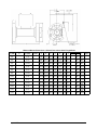
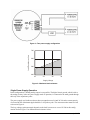
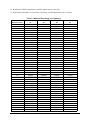
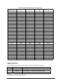
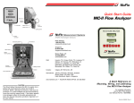
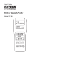
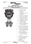
NUFLOTM
Series 1000
Watercut Monitor
User Manual
Manual No. 100080001, Rev. 01
© 2007 Cameron International Corporation (“Cameron”).
All information
contained in this publication is confidential and proprietary property of Cameron. Any
reproduction or use of these instructions, drawings, or photographs without the
express written permission of an officer of Cameron is forbidden.
All Rights Reserved.
Printed in the United States of America.
Manual No. 100080001, Rev.01
April 2007
Table of Contents
Introduction .............................................................................................................. 1
Specifications........................................................................................................... 1
Installation................................................................................................................ 1
Electrical Connections .......................................................................................... 4
Power Supply Configurations................................................................................. 5
Two Power Supply Operation ............................................................................... 5
Single Power Supply Operation............................................................................ 6
Calibration ................................................................................................................ 7
Calibration of the Crystal Controlled Oscillator ..................................................... 8
Analog Output Calibration..................................................................................... 8
Spare Parts List...................................................................................................... 10
April 2007
i
ii
April 2007
Introduction
The NuFlo Series 1000 Watercut Monitor consists of the NuFlo Capacitance Probe and additional circuit
cards. The frequency generated by the probe oscillator circuit varies according to the watercut of the
emulsion flowing through the capacitance probe. This frequency, however, does not vary linearly with the
watercut; the additional circuitry compensates for this non-linearity and yields a linear 4-20-mA current
output signal.
NuFlo watercut monitors are CSA-certified as explosion-proof for Division 1, Class I, Group C & D
hazardous locations.
Specifications
Watercut Range
0 to 100 percent (other watercut ranges are available - consult
your Cameron representative)
Input Power
(terminals 3 & 4)
12 to 30 VDC at 150 mA max.
Current Loop Power
(terminals 1 & 2)
24 to 30 VDC at 24 mA max. Power is customer-supplied and
must have less than 5mVac ripple.
Output Current Operating
Range
4 mA to 20 mA (adjustable)
Accuracy
±1% watercut over 0 to 50% range with homogeneous emulsion*
Pressure Rating
Varies with end connection (see pages 2 and 3)
Operating Temperature
0°F to 158°F (-17°C to 70°C)
Probe Body Material
Stainless Steel 316/316L
Probe Flange Material
Carbon Steel – ANSI B16.5, Mat’l Group 1.1
* Due to changes in the phase of oil that occur at watercuts above 50% and the inability to
determine the point at which these changes will occur, the accuracy of watercut measurements
above 50% cannot be predicted.)
Installation
Watercut monitors must be installed vertically, with either end up. This orientation helps maintain a
constant liquid fill with no trapped air. The monitor’s position should allow easy access to the circuit
board housing to facilitate calibration and maintenance. See pages 2 and 3 for dimensions of watercut
monitors with various style and size connections.
April 2007
1
Watercut Monitor Dimensions—NPT Male Threaded Ends
Nom. Size
Thread
in. (mm)
Type
2
2-in. API LP
(50)
Max. WP
psi (MPa)
1000
(6.9 Mpa)
Part No.
A
100079704 10.00
(254)
B
2.37
(60.2)
C
D
E
8.23
6.21
3.49
(209) (157.7) (88.6)
Watercut Monitor Dimensions—Victaulic Grooved Ends
Nom. Size
in. (mm)
2
(50)
3
(80)
2
Groove
Type
2-in. ES
3-in. ES
Max. WP
psi (MPa)
1000
(6.9 Mpa)
1000
(6.9 Mpa)
Part No.
A
B
C
D
E
F
G
H
100079705 10.00
2.37
8.23
6.21
2.25 0.255 0.562 3.49
(254) (60.2) (209) (157.7) (57.2) (6.5) (14.3) (88.6)
101002253 12.00
3.50
9.16
6.76
3.34 0.255 0.562 4.04
(304.8) (88.9) (232.7) (171.7) (84.8) (6.5) (14.3) (102.6)
April 2007
Watercut Monitor Dimensions—Raised-Face Carbon Steel Flanged Ends
Flange Size (ANSI)
in. (mm)
lb
2
150
(50)
2
300
(50)
2
600
(50)
3
150
(80)
3
300
(80)
3
600
(80)
4
150
(100)
4
300
(100)
4
600
(100)
6
150
(150)
6
300
(150)
6
600
(150)
April 2007
Max. WP
psi (MPa)
285
(1.96)
740
(5.10)
1480
(10.20)
285
(1.96)
740
(5.10)
1480
(10.20)
285
(1.96)
740
(5.10)
1480
(10.20)
285
(1.96)
740
(5.10)
1480
(10.20)
Part No.
A
100079706 10.00
(254)
100079707 10.00
(254)
100079708 10.00
(254)
101002254 12.00
(304.8)
101002255 12.00
(304.8)
101309649 12.00
(304.8)
100079709 12.00
(304.8)
101211166 12.00
(304.8)
101002256 12.00
(304.8)
100079710 12.00
(304.8)
120125478 12.00
(304.8)
101001289 12.00
(304.8)
B
6.00
(152.4)
6.50
(165.1)
6.50
(165.1)
7.50
(190.5)
8.25
(209.6)
8.25
(209.6)
9.00
(228.6)
10.00
(254)
10.75
(273.1)
11.00
(279.4)
12.50
(317.5)
14.00
(355.6)
C
9.86
(250.4)
10.11
(256.8)
10.11
(256.8)
11.17
(283.7)
11.54
(293.1)
11.54
(293.1)
12.42
(315.1)
12.92
(328.2)
13.30
(337.8)
14.50
(368.3)
15.25
(387.4)
16.00
(406.4)
D
6.21
(157.7)
6.21
(157.7)
6.21
(157.7)
6.77
(172)
6.77
(172)
6.77
(172)
7.27
(184.7)
7.27
(184.7)
7.27
(184.7)
8.35
(212.1)
8.35
(212.1)
8.35
(212.1)
E
3.62
(91.9)
3.62
(91.9)
3.62
(91.9)
5.00
(127)
5.00
(127)
5.00
(127)
6.19
(157.2)
6.19
(157.2)
6.19
(157.2)
8.50
(215.9)
8.50
(215.9)
8.50
(215.9)
F
0.69
(17.5)
0.81
(20.6)
1.00
(25.4)
0.88
(22.4)
1.06
(26.9)
1.25
(31.8)
0.88
(22.4)
1.19
(30.2)
1.5
(38.1)
0.94
(23.9)
1.38
(35.1)
1.88
(47.8)
H
G
Bolt Qty.
0.06
4
(1.6)
0.06
8
(1.6)
0.25
8
(6.4)
0.06
4
(1.6)
0.06
8
(1.6)
0.25
8
(6.4)
0.06
8
(1.6)
0.06
8
(1.6)
8
0.25
(6.4)
0.06
8
(1.6)
0.06
12
(1.6)
0.25
12
(6.4)
Dia.
3/4
(19.1)
3/4
(19.1)
3/4
(19.1)
3/4
(19.1)
7/8
(22.2)
7/8
(22.2)
3/4
(19.1)
7/8
(22.2)
1
(25.4)
7/8
(22.2)
7/8
(22.2)
1 1/8
(28.6)
I
Angle, °
3.49
45
(88.6)
3.49
22.5
(88.6)
3.49
22.5
(88.6)
4.05
45
(102.9)
4.05
22.5
(102.9)
4.05
22.5
(102.9)
4.55
22.5
(115.6)
4.55
22.5
(115.6)
4.55
22.5
(115.6)
5.61
22.5
(142.5)
5.61
15
(142.5)
5.61
15
(142.5)
3
Electrical Connections
To maintain the explosion-proof rating of this device, the electrical installation must conform to all
applicable electrical code requirements. The watercut monitor must be connected to a substantial earth
ground and a conduit seal must be installed within 18 in. of the instrument. The conduit seal may be
purchased locally.
To connect the earth ground to the watercut monitor, perform the following steps:
1. Unscrew the circuit card housing cover.
2. Note the orientation of both circuit cards, and then carefully remove them.
3. Connect the ground using the grounding screw and wire terminal in the bottom of the card housing.
4. Reinstall the Lower Watercut Monitor circuit card (Part No. 100005135) as follows:
a. Insert the two banana plugs on the card into the jacks in the bottom of the card housing.
b. Insert the antenna connection screw through the center hole of the card and tighten securely.
5. Reinstall the Upper Watercut Monitor circuit card (Part No. 100005136) as follows:
a. Insert the connecting pins on the bottom of the upper card into the socket on the lower card.
b. Place two screws through the upper card into the lower card standoffs to attach the upper card to
the lower card, and tighten securely.
6. Reinstall the housing cover.
The watercut monitor’s flexible design allows it to be easily connected to its host equipment (see Figure
1). The 4-20-mA output is optically isolated from the other circuitry in order to provide a floating analog
output. This mode of operation requires two power supplies that are isolated from the host system or the
use of the optional isolating power supply board.
In any configuration, the load in the current loop must be placed between the “-“ output terminal of the
4-20 mA output (terminal 2) and the power supply common.
4
April 2007
Figure 1—Electrical connections
Power Supply Configurations
Two Power Supply Operation
In this configuration, a floating analog output is possible. In the two-power supply mode of operation, the
4-20 mA is powered by one supply, while the second power supply runs the digital circuitry. Because the
digital circuit ground is almost always connected to the earth ground through the body of the capacitance
probe, this power supply cannot be floating.
The digital circuitry power supply must have an output of 12 to 30 Vdc. The watercut monitor should be
wired as shown in Figure 2. A minimum 200-mA current capacity is recommended for this power supply.
Maximum ripple should be 5 mV peak-to-peak.
The power supply for the analog output must have an output between 24 and 30 Vdc, depending on the
load. Maximum ripple should by 5 mV peak-to-peak. Refer to Figure 3 for the loop voltage required.
April 2007
5
Figure 2—Two power supply configuration
Load Resistance, ohms
700
600
500
400
24
26
28
30
Supply Voltage
Figure 3—Maximum load resistance
Single Power Supply Operation
In this configuration, a floating analog output is not possible. The digital circuit ground, which is tied to
the analog circuitry in the one-power-supply mode of operation, is connected to the earth ground through
the body of the capacitance probe.
The power supply used in this mode must have an output between 24 and 30 Vdc and a current capacity
of at least 200 mA. Maximum ripple should be 5 mV peak-to-peak. The watercut monitor must be wired
as shown in Figure 4.
The loop voltage requirement again depends on the load, but can never exceed 30 Vdc in this configuration. Refer to Figure 3 for maximum load resistance values.
6
April 2007
Figure 4—Single power-supply configuration
Calibration
Every NuFlo Capacitance Probe is calibrated before it leaves the factory. However, since the crude oil
chemistry and fluid temperature used during the factory calibration may differ from the chemistry and
temperature of fluid at the field location, adjustment of the capacitance probe is usually necessary.
For proper calibration, the probe must be completely liquid filled with no air trapped inside. The probe
may be installed or removed from the flow line during calibration.
To check the calibration of a capacitance probe, perform the following steps:
1. Fill the probe with clean, dry crude oil from the location to be served. Alternately, a sample of oil
with a non-zero watercut may be used if the watercut percentage is accurately known and the
emulsion is homogeneous.
2. Set the probe output frequency.
•
If clean dry crude oil is used, set the probe output to 1025.000 kHz.
•
If a crude sample with a non-zero watercut is used, perform the following:
a. Verify the exact watercut percentage.
b. Look up the frequency that corresponds to the watercut percentage and probe size in Table 1,
pages 9 and 10, and set the probe output accordingly.
3. Bring the entire assembly to the temperature it will experience in service.
Note—This step is extremely important since differences between calibration temperature and operating
temperature can cause significant measurement inaccuracies.
4. Observing polarity, connect a 12- to 30-Vdc power supply to terminals 3 and 4 and check the
frequency on terminals 5 and 6 with a frequency counter. Allow the unit to stabilize until the output
frequency remains constant. The target frequency may be found in Table 1, pages 9 and 10.
April 2007
7
5. If the probe frequency is not within 15 Hz of the value specified in the table, adjust the probe
oscillator as follows:
a. Unscrew the pipe plug in the trimmer capacitor access hole.
b. Using a non-metallic tool, adjust the trimmer capacitor on the probe circuit assembly until the
output frequency agrees with the table entry.
c. Replace the pipe plug in the trimmer capacitor access hole. This is the only adjustment required
to calibrate the capacitance probe.
Calibration of the Crystal Controlled Oscillator
The crystal-controlled oscillator, which controls the gate period during which probe pulses are counted, is
calibrated at the factory and should not require adjustment. However, the frequency may be adjusted by a
trimmer capacitor on the Lower Watercut Monitor circuit card.
For best accuracy, bring the unit to operating temperature and allow it to stabilize before adjusting the
trimmer capacitor.
A hole in the Upper Watercut Monitor circuit card allows easy access to the trimmer capacitor with a
small adjustment screwdriver. The trimmer cap should be adjusted until the frequency from the oscillator
is 32.768 kHz, plus-minus 1 Hz. The crystal frequency may be monitored on test point T1 on the Upper
Watercut Monitor circuit card.
Analog Output Calibration
The analog output is calibrated at the factory and should not require adjustment. If field adjustment is
needed, note that optimum accuracy will be achieved by calibrating the unit at the temperature it will see
in service.
1. Connect the watercut monitor as per Figure 2 or Figure 4, replacing the load in either case with an
accurate milliammeter that reads to 0.01 mA accuracy.
2. Connect a frequency generator to terminals 5 and 6.
3. Set the output of the generator for a 0- to 2-volt square wave at 1025.000 kHz plus-minus 15 Hz.
4. Adjust the “ZERO” potentiometer on the Upper Watercut Monitor circuit card until the analog output
is 4.00 mA.
5. Remove the frequency generator signal from pins 5 and 6.
6. Place a jumper across terminals 5 and 6 to short the terminals together.
7. Adjust the “SPAN” potentiometer, which is also on the Upper Watercut Monitor circuit card, until the
analog output is 20.0 mA.
8. Remove the jumper from terminals 5 and 6.
9. Reapply the 1025.000 kHz signal to terminals 5 and 6.
10. Adjust the “ZERO” potentiometer for 4.00 mA loop current.
11. Remove the signal and reconnect the jumper to terminals 5 and 6.
8
April 2007
12. Readjust the “SPAN” potentiometer until the output current is 20.0 mA.
13. Repeat Steps 8 through 12 several times if necessary until the adjustments cease to interact.
Table 1—Watercut Percentage vs. Frequency
Watercut Percent
0.0
0.1
0.2
0.3
0.4
0.5
0.6
0.7
0.8
0.9
1.0
1.1
1.2
1.3
1.4
1.5
1.6
1.7
1.8
1.9
2.0
2.5
3.0
3.5
4.0
4.5
5.0
5.5
6.0
6.5
7.0
7.5
8.0
8.5
9.0
9.5
10.0
11.0
12.0
13.0
14.0
15.0
16.0
April 2007
2" Probe Frequency 3" Probe Frequency 4" Probe Frequency 6" Probe Frequency
Hz
Hz
Hz
Hz
1025000
1025000
1025000
1025000
1024890
1024908
1024966
1024930
1024780
1024816
1024932
1024860
1024670
1024724
1024898
1024790
1024560
1024632
1024864
1024720
1024450
1024540
1024830
1024646
1024334
1024445
1024740
1024572
1024218
1024350
1024650
1024494
1024102
1024255
1024560
1024416
1023986
1024160
1024470
1024338
1023870
1024065
1024380
1024260
1023754
1023970
1024290
1024182
1023638
1023875
1024200
1024104
1023522
1023780
1024110
1024026
1023406
1023685
1024020
1023948
1023290
1023590
1023930
1023870
1023170
1023491
1023838
1023788
1023050
1023392
1023746
1023736
1022930
1023293
1023654
1023684
1022810
1023194
1023562
1023572
1022690
1023095
1023470
1023460
1022090
1022600
1023010
1023049
1021475
1022090
1022530
1022630
1020860
1021580
1022050
1022207
1020225
1021055
1021555
1021770
1019590
1020530
1021060
1021330
1018935
1019990
1020550
1020875
1018280
1019450
1020040
1020417
1017610
1018890
1019515
1019915
1016940
1018330
1018990
1019414
1016250
1017760
1018445
1018965
1015560
1017190
1017900
1018520
1014850
1016600
1017340
1018020
1014140
1016010
1016780
1017519
1013415
1015405
1016210
1017010
1012690
1014800
1015640
1016499
1011950
1014175
1015050
1015970
1010445
1012915
1013850
1014895
1008900
1011625
1012620
1013790
1007325
1010300
1011360
1012655
1005730
1008945
1010065
1011490
1004120
1007560
1008745
1010295
1002470
1006140
1007400
1009070
9
Table 1—Watercut Percentage vs. Frequency
Watercut Percent
17.0
18.0
19.0
2" Probe Frequency 3" Probe Frequency 4" Probe Frequency 6" Probe Frequency
Hz
Hz
Hz
Hz
1000740
1004685
1006010
1007815
998960
1003120
1004570
1006530
997160
1001480
1003085
1005210
20.0
21.0
22.0
23.0
24.0
25.0
26.0
27.0
28.0
29.0
30.0
31.0
32.0
33.0
34.0
35.0
36.0
37.0
38.0
39.0
40.0
41.0
42.0
43.0
44.0
45.0
46.0
47.0
48.0
49.0
50.0
995320
993435
991495
989490
987430
985320
983155
980965
978715
976385
974050
971700
969315
966920
964505
962070
959620
957155
954675
952175
949660
947130
944580
942015
939435
936840
934290
931695
929025
926395
923810
999835
998140
996395
994600
992755
990860
988915
986925
984885
982790
980645
978450
976205
973830
971385
968850
966270
963745
961180
958585
955950
953305
950600
947830
945055
942245
939395
936510
933635
930845
928085
1001545
999955
998315
996620
994880
993090
991245
989355
987415
985420
983380
981270
979085
976850
974560
972215
969820
967370
964865
962310
959700
957035
954315
951545
948720
945840
942910
939980
937155
934420
931710
1003860
1002315
1000730
999265
997740
996155
994510
992800
991035
989210
987320
985370
983350
981285
979170
977000
974800
972555
970260
967920
965530
963090
960605
958070
955485
952850
950165
947430
944650
941895
939245
Spare Parts List
The following spare parts are recommended for the Series 1000 Watercut Monitor:
Quantity
1
1
1
Part Number
100005135*
100005136
100015379
Description
Circuit Assembly – Lower Watercut Monitor Board
Circuit Assembly – Upper Watercut Monitor Board
Antenna O-ring
* Specify probe size and watercut range.
10
April 2007
WARRANTY - LIMITATION OF LIABILITY: Seller warrants only title to the products,
software, supplies and materials and that, except as to software, the same are free
from defects in workmanship and materials for a period of one (1) year from the date
of delivery. Seller does not warranty that software is free from error or that software
will run in an uninterrupted fashion. Seller provides all software "as is". THERE ARE
NO WARRANTIES, EXPRESS OR IMPLIED, OF MERCHANTABILITY, FITNESS
OR OTHERWISE WHICH EXTEND BEYOND THOSE STATED IN THE
IMMEDIATELY PRECEDING SENTENCE. Seller's liability and Buyer's exclusive
remedy in any case of action (whether in contract, tort, breach of warranty or
otherwise) arising out of the sale or use of any products, software, supplies, or
materials is expressly limited to the replacement of such products, software,
supplies, or materials on their return to Seller or, at Seller's option, to the allowance
to the customer of credit for the cost of such items. In no event shall Seller be liable
for special, incidental, indirect, punitive or consequential damages. Seller does not
warrant in any way products, software, supplies and materials not manufactured by
Seller, and such will be sold only with the warranties that are given by the
manufacturer thereof. Seller will pass only through to its purchaser of such items the
warranty granted to it by the manufacturer.