1
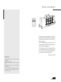
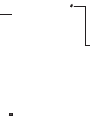
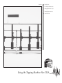
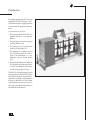
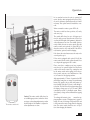
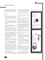
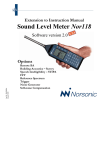
user documentation
nor211A
The Nor-211A is a mains operated tapping machine with optional battery operation designed
to meet the requirements given
in ISO 140 parts 6 and 7 stating
that a tapping machine is
needed as sound source for impact noise measurements.
Although the tapping machine
comes with steel hammers as
standard, a rubber hammer version retrofit is also available.
For convenience a remote on/off
control is available as an option.
tapping machine
Im211A _1Ed1R2En – May2004
Nor-211A User Guide
Im211A_1Ed1R2En – May 2004 Edition
Production Notes: This manual was created
electronically using Adobe PageMaker 6.5.
Artworks were made with Adobe PhotoShop
5.5 and FreeHand 8. Proofs were made on HP
LaserJet 4050PS and 4MV PostScript printers.
RIP and final printout were made at Allkopi,
Høvik, Norway.
Norsonic is a registered trademark of Norsonic
AS. All other brand or product names are
trademarks or registered trademarks of their respective companies.
Every effort has been made to supply complete and accurate information. However, Norsonic AS assumes no responsibility for the use
of – nor for the consequential damages of the
use of – this information and/or the instrumentation described herein. Furthermore Norsonic
AS assumes no responsibility for any infringement of the intellectual property rights of third
parties, wherever applicable, which would result from such use.
Norsonic AS reserves the right to amend any
of the information given in this manual in order
to take account of new developments.
If you wish to communicate with us, please
feel welcome. Our address is:
Norsonic AS, P.O. Box 24, N-3421 Lierskogen,
Norway.
Tel: +47 3285 8900,
Fax: +47 3285 2208
e-mail: [email protected]
Find us on the world wide web:
www.norsonic.com
Copyright © Norsonic AS 1994–2004.
All rights reserved
Preface to this Edition
Thank you for choosing Norsonic. The tapping machine Nor-211A has been designed
to provide you with many years of safe, reliable operation.
We recommend that you take your time to
read through this little booklet before you
start using the equipment.
For optimum use of the tapping machine
we recommend that you get yourself a
copy of relevant standards applicable to
you tapping machine application.
Tranby, May 2004
Caution!
The tapping machine Nor-211A is IP20
protected.
For indoor use only!
The unit must be protected from rain and
dust.
Moving parts! Never move the unit while
it is powered.
Remove the mains cable before making
any check of hammer height or adjustments to the unit.
3
4
Contents
06 Introduction
07 Fall Height Adjustments
08 Changing Hammer Type
09 Making Measurements
10 Specifications
10'4"
16'8"
Using the Tapping Machine Nor-211A
Introduction
The tapping machine Nor-211A has been
designed to fulfil ISO 140 parts 6 and 7.
This Standard requires a tapping machine
as sound source for impact noise measurements.
The requirements are as follows:
• The tapping machine should have five
hammers placed in a line spanning
400 mm
• The time between successive impacts
should be 100 ms ± 5 ms
• The effective mass of each hammer
should be 0.5 kg (within 2.5%)
• The dropping of a hammer on a flat
floor should be equivalent – with respect to the momentum – to a free,
frictionless drop of 40 mm (within
2.5%).
• The part of the hammer that strikes the
floor should be a cylinder made of brass
or steel, 3 cm in diameter, with a spherical end having a radius of 50 cm.
The Nor-211A has been designed to meet
these requirements. The Nor-211A/02 has
been further extended to also meet the requirements for rubber coated hammers to
be used on delicate floors. These rubber
coated hammers are, however, easy to replace with conventional steel hammers as
described later in this manual.
6
Fall Height Adjustments
Before you make measurements with your
Nor-211A, the fall height of all the hammers
should be checked and adjusted, if needed.
The check should be carried out on a flat,
horizontal floor or a horizontal table. A
tool for this is included, viz. the small rod
mounted onto the tapping machine – see
the Fig to the left.
The length of this rod is 40.8mm. The
0.8mm extra has been added to compensate for the friction occurring during the fall,
thereby ensuring that the effective fall is the
required 40mm.
Do as follows:
1. Turn the main gear until one of the hammers is at its maximum height
2. Place the rod under the hammer and
verify that the hammer is less than 1mm
above the top of the rod.
Detach this rod and use it to
check the fall height of the
hammers – see text for details
3. Repeat for all hammers.
The feet are locked in
position by means of
the screw and the nut
If adjustments are needed:
1. Adjust the three feet of the tapping machine until the correct fall height
(40.8mm – see above) is obtained. Make
sure the machine is standing level (in both
directions) while doing this.
2. Once an acceptable fall height has been
reached (for all hammers) lock the position of each foot using the enclosed
19 mm wrench on the screw and the nut.
Put the fall height control rod back in
place.
7
Changing Hammer Type
Change of hammer type applies to units
supplied with extension 1 (rubber tipped
hammers) only.
The extension 1 includes a pin tool which
fits into the hole of each hammer and a
14 mm wrench.
Do as follows:
1. Insert the pin in the hole of the hammer
2. Use the 14 mm wrench as shown in the
Fig.
3. Give the pin a quick push (knock it) to
loosen the hammer. Do not attempt to
unscrew slowly and gently as this may
cause pin deformation.
4. The rubber hammers are mounted on a
bracket on the end panel of the machine.
The replaced set of hammers fit on the
same bracket.
The two types of hammers are of the same
length, However, we still recommend that
you verify the fall height after hammer
replacement.
Use the pin and the wrench when
unscrewing a hammer. Give the pin
a quick push rather than slowly unscrewing to avoid pin deformation
8
Operation
In its standard version the unit is operated off
mains, but the units equipped with option 211A/
01 can also be battery operated by means of a buildin battery. This option cannot be installed as a retrofit.
LED
When connected to mains a green LED is lit.
Start button
The mains switch has three positions; off, ready
and start/stop.
The switch shall always be set to off (upper position) for safety reasons when the unit is not in use
or when the fall height of the hammer is adjusted or
other adjustments are done. The middle position,
ready, enables the unit to receive signals from the
remote control unit (optional). A green LED is lit
when the switch is set to ready mode. If the LED is
red, batteries (optional) need recharging.
Push down the mains button starts the unit, and a
second push stops it.
If the unit is equipped with option 211A/03 the
remote control can be used to operate the unit. Press
on to begin the tapping and off to end it.
Please note that a complete start/stop sequence
must always be operated either from the mains
switch or the remote control. E.g. starting the unit
by the mains switch and stopping it from the remote control unit may cause malfunction of the
on/off control of the tapping machine.
After approximately 1.5 hours of operation the LED
will change from green to orange colour indicating
battery low (applies only to units with battery option installed) and after 2-3 hours it will change to
red colour. The Nor211A will stop functioning when
the battery voltage gets too low. The unit is RPM
controlled by means of a feedback system. Hence,
a low battery voltage will not influence the tapping
speed.
The remote control unit
Caution! The mains switch shall always be
set to Off (upper position) when the unit is
not in use or when charging batteries or when
the fall height of the hammer is adjusted or
other adjustments are done.
To recharge the batteries, just c
onnect the tapping machine to mains. Charging time is approximately 12 hours. No damage is imposed if the unit
is left connected to mains longer than the charging
time. The mains switch should be set to off position when charging the batteries.
9
Making Measurements
A measurement according to the ISO 140
part 7 will normally yield repeatable results when the room volume exceeds
25 m3.
Do as follows:
machine positions. For each tapping
machine position in the sending room,
one of six randomly distributed microphone positions is chosen in the receiving room.
1. Choose six positions at random on the
floor. No position should be closer to
the room boundaries (the walls) than 1.0
metre.
The measuring time should always exceed
5 seconds.
In cases of non-isotropic floor constructions (as will be the case with rib beam
constructions), more positions may be
required.
Alternatively a rotating microphone boom
(available separately from Norsonic AS)
may be used. A minimum sweep radius of
0.7 metre is then required. The plane of the
traverse should be inclined relative to the
room boundaries and the microphone
should never be closer to any of the room
boundaries than 0.5 metre.
2. The Nor-211A should be oriented at 45°
to the direction of the beams or ribs
3. The measurement of impact noise is
based on absolute sound level measurements (as opposed to e.g. the relative
measurements used when capturing
decays for reverberation time calculations). Hence, you should calibrate your
measuring equipment before you start
making measurements. Consult the
documentation accompanying the rest
of your equipment.
4. Measure the background noise level in
the receiving room. Use a bandwidth of
1/3 octave bands in the range 100 Hz to
3.15 kHz. This is the standard range for
building acoustics measurements.
No microphone position should be closer
to the room boundaries than 0.5 m.
The averaging time when measuring with
a rotating boom should be equal to the
traverse time of the boom, but never
shorter than 30 seconds.
7. Sequentially select, measure and average the results from the other tapping
machine positions in order to average
out local phenomena.
8. Measure the reverberation times for the
individual 1/3 octave band frequencies
in the receiving room. At least three
positions are required and at least two
measurements should be made in each
position.
5. In the sending room, start the tapping
machine and verify that the excitation
level is at least 10 dB above the background noise level. Check this for each
individual frequency band. If this requirement fails to be met, special precautions must be taken.
The equivalent absorption area A may now
be calculated from A = [0.163 × V]/T and
the normalised impact sound pressure
level L’n may then be calculated from:
6. In the receiving room measure the
sound level for the six different tapping
in which A0 equals 10 m2. You will now be able
to calculate Ln,W as described in ISO 717.
10
L’n = Li + 10 × log(A/A0) [dB]
1234567890123456789012345678
1234567890123456789012345678
1234567890123456789012345678
1234567890123456789012345678
SENDING ROOM
1234567890123456789012345678
1234567890123456789012345678
1234567890123456789012345678
1234567890123456789012345678
Use altogether six
1234567890123456789012345678
1234567890123456789012345678
randomly selected
1234567890123456789012345678
positions on the floor.
1234567890123456789012345678
1234567890123456789012345678
1234567890123456789012345678
1234567890123456789012345678
1234567890123456789012345678
1234567890123456789012345678
1234567890123456789012345678
1234567890123456789012345678
1234567890123456789012345678
1234567890123456789012345678
1234567890123456789012345678
1234567890123456789012345678
1234567890123456789012345678
1234567890123456789012345678
The tapping machine should
1234567890123456789012345678
1234567890123456789012345678
be oriented 45° to the direction
1234567890123456789012345678
1234567890123456789012345678
of beams or ribs
1234567890123456789012345678
1234567890123456789012345678
1234567890123456789012345678
1234567890123456789012345678
1234567890123456789012345678
1234567890123456789012345678
RECEIVING ROOM
1234567890123456789012345678
1234567890123456789012345678
1234567890123456789012345678
1234567890123456789012345678
1234567890123456789012345678
1234567890123456789012345678
1234567890123456789012345678
1234567890123456789012345678
Use one of six
1234567890123456789012345678
1234567890123456789012345678
randomly selected
1234567890123456789012345678
1234567890123456789012345678
microphone
1234567890123456789012345678
1234567890123456789012345678
positions per
1234567890123456789012345678
tapping machine
1234567890123456789012345678
1234567890123456789012345678
location, or use a
1234567890123456789012345678
1234567890123456789012345678
rotating boom
1234567890123456789012345678
1234567890123456789012345678
1234567890123456789012345678
1234567890123456789012345678
1234567890123456789012345678
1234567890123456789012345678
1234567890123456789012345678
1234567890123456789012345678
1234567890123456789012345678
1234567890123456789012345678
1234567890123456789012345678
1234567890123456789012345678
1234567890123456789012345678
1234567890123456789012345678
1234567890123456789012345678
1234567890123456789012345678
1234567890123456789012345678
1234567890123456789012345678
1234567890123456789012345678
1234567890123456789012345678
Specifications
Hammers:
Five hammers @ 500 g
Effective fall height:
40 mm (adjustable)
Tapping sequence:
10 impacts per second, rpm controlled
via feedback loop
Power:
100–120 V/60Hz or 200–240 V/50 Hz
Battery operation (optional):
from built-in Li-Ion rechargeable battery
Battery operating time before recharging is required: Typ. 2 hours
Battery charging time: 12 hours
Fuse:
0.4 A (100–120 Vac)
0.2 A (200–240 Vac)
CE conformity:
EMC compliance according to
EN 50081-1 and EN 50082-1
Electrical safety according to
EN 61010-1-1993
Machine directive 89/392
Accessories included:
Mains cable, 17 mm wrench, pin for
removal of the small rod used for
verification of the fall height.
Units equipped with option 2 (rubber
hammers) are in addition supplied with:
14 mm wrench and a special pin for
removal of rubber hammers and the
small verification rod. The latter replaces
the pin supplied with standard versions
of the Nor-211A.
Power consumption:
15 W
Dimensions:
72.5 × 23.0 × 32.0 [cm] (w × d × h)
Weight:
10 kg (22 lbs)
12.5 kg (28.5 lbs) including option 1
(rubber hammers)
Specifications subject to change without
further notice.
11
Declaration of Conformity
We, Norsonic AS, Gunnersbråtan 2, Tranby, Norway, declare under our sole responsibility that the product:
Tapping Machine NOR-211A
FROM SERIAL NUMBER 18220
to which this declaration relates, is in conformity with the following standards or
other normative documents:
Safety:
EN61010-1:1993 for portable equipment and pollution category 2.
EMC:
EN 50081-1
EN 50082-1
following the provisions of the LVD-, EMC- and Machine Directive.
This product has been manufactured in compliance with the provisions of the relevant internal Norsonic production standards.
All our products are tested individually before they leave the factory.
This Declaration of Conformity does not affect our warranty obligations.
Tranby, January 1996
Dagfinn Jahr
Quality Manager
The declaration of conformity is given according to EN 45014 and ISO/IEC Guide 22.
Norsonic AS, P.O. Box 24, N-3420 Lierskogen, Norway