1
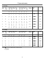
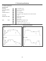
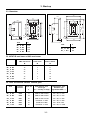
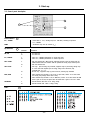
GE Power Controls
STATIC
SOFT STARTER
ASTAT-SD
USER MANUAL
REMARKS :
1. Read this manual throughly before using the ASTAT-SD, and store in a safe place
for reference.
2. Make sure that this manual is delivered to the end user
3. CE MARKING
When using ASTAT-SD in the EU, compliance with EMC is required.
ASTAT-SD is according with the generic EN 50081-2 and EN 50082-2
Index
Section 1. Types and powers ........................................................................................................
1-1
1-2
1-1
IEC ratings ........................................................................................................................
UL ratings ..........................................................................................................................
1-1
1-1
Section 2. Technical specifications ..............................................................................................
2-1
2-1
2-2
2-3
General specifications .......................................................................................................
Operating modes ...............................................................................................................
Recommended diagrams ..................................................................................................
2-1
2-2
2-3
Section 3. Start-up. ........................................................................................................................
3-1
3-1
3-2
3-3
3-4
3-5
3-6
3-7
Equipment installation .......................................................................................................
Dimensions .......................................................................................................................
ASTAT-SD total losses at 100% rated current ....................................................................
Fuses and isolation contactor selection guide ...................................................................
Control panel description ...................................................................................................
Start-up .............................................................................................................................
Error detection ...................................................................................................................
ii
3-1
3-2
3-2
3-2
3-3
3-4
3-5
ASTAT-SD . Static soft starters
1. Types and powers
1-1. IEC Ratings
Current
rating
Max.
starting
current
Standard duty (300%, 30 sec.)
220V / 380V / 440V 480V /
240V 415V
500V
Heavy duty (450%, 30 sec.)
220V / 380V / 440V 480V /
240V 415V
500V
Degree of
protection
TYPE
(1)
Cooled
A
A
kW
HP
kW
HP
kW
HP
kW
HP
kW
HP
kW
HP
kW
HP
kW
HP
5
25
1,1
1,5
2,2
3
2,2
3
3
4
1,1
1,5
2,2
3
2,2
3
3
4
IP-20
QS o BNA
Natural
9
45
2,2
3
4
5,5
4
5,5
5,5
7,5
2,2
3
4
5,5
4
5,5
5,5
7,5
IP-20
QS o DNA
Natural
12
60
3
4
5,5
7,5
6,3
7,5
7,5
10
3
4
5,5
7,5
6,3
7,5
7,5
10
IP-20
QS o FNA
Natural
16
80
4
5,5
7,5
10
7,5
10
10
13,5
3,7
5
6,3
7,5
7,5
10
10
13,5
IP-20
QS o GNA
Natural
22
110
5,5
7,5
10
13,5
11
15
13
18
5,5
7,5
10
13,5
11
15
13
18
IP-20
QS o HNA
Natural
34
170
7,5
10
15
20
18,5
25
20
25
7,5
10
15
20
17
20
20
25
IP-00
QS o INA
Natural
Degree of
protection
TYPES
(1)
Cooled
1-2. UL Ratings
Current Max.
rating
starting
current
Standard duty (300%, 30 sec.)
200V 230V 460V
Heavy duty (450%, 30 sec.)
200V 230V 460V
A
A
HP
HP
HP
HP
HP
HP
5
25
1
1
3
1
1
3
IP-20
QS o BNA
Natural
9
45
2
2
5
2
2
5
IP-20
QS o DNA
Natural
12
60
3
3
7,5
3
3
7,5
IP-20
QS o FNA
Natural
16
80
3
5
10
3
5
10
IP-20
QS o GNA
Natural
22
110
5
7,5
15
5
7,5
15
IP-20
QS o HNA
Natural
34
170
10
10
25
7,5
7,5
20
IP-00
QS o INA
Natural
(1) Replace o by one of the following numbers, according line voltage :
1 = 200 - 440 V
2 = 460 - 500 V
1-1
2. Technical specifications
2-1. General specifications
Control
Specifications
Control system
Digital system with microcontroller. Starting ramp with progressive increase
in voltage and current limitation
Initial voltage (pedestal)
%
40 - 90 Un
Starting torque
%
15 - 80 Mdirect start
Kick start
%
90 Un (80% Mdirect start), 400ms
Current limitation
Acceleration ramp time
Inputs / Outputs
Protections
s
0,5 to 60
Energy savings
Output voltage reduction according to power factor
Override
Fixed output voltage permanently equal to supply voltage
Deceleration time by ramp
Operation
2 to 5 x In
s
max. 2 x t acceleration ramp (as per energy savings state)
External control
Start - Stop
Acceleration phase
Adjustable time
Permanent phase
Energy savings / override choice
Stop phase
Power cut-off / ramp choice
Inputs
2 optical couplings for Run / Stop commands
Outputs
1 relay for Run / End of ramp (1NO) - Selectable
Current limit
Adjustable from 2In to 5In
Loss on input phase
s
Trip at 3
Thyristor short circuit
ms
Trip at 200
Loss on output phase
s
Trip at 3
Supply frequency error
Hz
If f < 48 ór f > 62, will not start
Error (CPU)
ms
60
Environmental
Temperature
ºC
0 to +55 (1)
conditions
Relative humidity
%
95 without condensation
Max. altitude
m
3000 (2)
Mounting positions
Vertical
Description of
1L1, 3L2, 5L3
Power supply inputs (max. 440 or 500 V, according Types) +10%, -15%
terminals
2T1, 4T2, 6T3
Outputs to motor
A1 / A2 , B1 / B2
Command supply inputs (110/120 - 220/240V AC) +10%, -15%
11, 14
Run/End of ramp internal relay output (1NO)
1, 57
Run command input
2, 57
Stop command input
3, 4
For future use
Output contact
Max. usage voltage
Vac
380
specs.
Thermal current Ith
A
8
AC-15
V/A
220 / 3 - 380 / 1
DC-15
V/A
max. 30 /3.5
Usage specifications
(1) Derate output current by 1,5% / ºC above 45ºC
2-1
(2) Derate output current by 1% / 100m above 1000 meters
2. Technical specifications
2-2. General specifications
Operating modes
Initial ramp
1
5 main frequency cycles
Initial voltage (pedestal)
1a
40 to 90% Un (adjustable)
Kick start
2
90% Un (choice)
Acceleration ramp (tramp)
3
0.5 to 60s (adjustable)
3a
Fast increase of output voltage when the motor reaches rated speed
Current limit
4
2 to 5 In
Permanent state Choice
5
Nominal voltage (Override)
5a
Nominal current
6
Energy savings
7
Motor power cut-off (stopped by inertia)
8
Deceleration ramp. Max. time 2 x tramp
8a
Evolution of current in deceleration ramp mode
Brake
Choice
Starting by current limitation
Starting by voltage ramp
Override
Override
t
t
Energy savings
Energy savings
t
t
2-2
2. Technical specifications
2-3. Recommended diagrams
Contacts with pulse function
Permanent contact
control voltage
110/120V AC
Start / Stop
control voltage
110/120V AC
F1
Start
Stop
FT1
F1
FT1
control voltage
220/240V AC
control voltage
220/240V AC
(1)
(1)
ASTAT SD
ASTAT SD
FT1
(2)
FT1
(2)
Pulse function with line contactor
Permanent contact with line contactor
control voltage
110/120V AC
Control
voltage
Start / Stop
control voltage
110/120V AC
F1
Start
Control
voltage
Stop
FT1
FT1
DC1
control voltage
220/240V AC
DC1
control voltage
220/240V AC
(*)
ASTAT SD
F1
(*)
(1)
ASTAT SD
FT1
(2)
(1)
FT1
(2)
(*) RUN function enabled
(*) RUN function enabled
(2) Use thermal relay if required by
local rules, selecting it according
to motor current
(1) These contacts allow for direct
action on contactors up to type
CL10A at 220V AC. See usage
characteristics for determining
the need for an auxiliary relay
2-3
3. Start-up
3-1. Equipment installation
CAUTION! DISCONNECT POWER BEFORE INSTALLING OR SERVICING
ONLY SPECIALIZED PERSONNEL SHOULD INSTALL THE EQUIPMENT AND ONLY AFTER
HAVING READ THIS USER'S GUIDE.
THE USER ITSELF IS RESPONSIBLE FOR ANY PHYSICAL INJURY OR MATERIAL DAMAGE
RESULTING FROM MISHANDLING THE EQUIPMENT.
IF YOU HAVE ANY DOUBTS ABOUT ANY PROCEDURE, PLEASE CONTACT YOUR
DEALER.
When installing equipment, keep the following points in mind
- The equipment should be installed vertically and hang over a platform
or bars. The vertical position is essential for proper cool air circulation
- Equipment should be well ventilated, at least keeping clearances as
indicated in the following illustration.
- Do not install equipment in environments containing explosive or
flammable gases, or near important heat sources
- When equipment is to be mounted on a platform subject to strong
vibrations, there should be an elastic base to protect the equipment.
- Do not install capacitors to correct the power factor between equipment
output and motor
- Signal wiring should be no longer than 5m, and should be separate
from power wires (line, motor, command relays, etc.) by at least 10cm,
and if they cross, they should do so at a 90º angle
- Relays and contactors located in the same housing as the equipment
should have an RC suppressor parallel to the coil (or a reverse diode,
if controled by DC).
3-1
3. Start-up
3-2. Dimensions
170
115,5
140
92
92
M4
40
128,5
200
118
A
118
80
128,5
M4
14,2
Ø 6
Ø 7
120
160
14,2
50
155
170
TYPE
A
QS _ B - N A
QS _ D - N A
QS _ F - N A
QS _ G - N A
150
150
180
180
TYPE
A
QS _ H - N A
QS _ I - N A
200
250
3-3. ASTAT-SD total losses at 100% rated current
TYPE
Power losses at
100% rated current
W
Control
circuit losses
W
Total losses
Power & Control
W
QS _ B - N A
15
2
17
QS _ D - N A
29
2
31
QS _ F - N A
35
2
37
QS _ G - N A
47
2
49
QS _ H - N A
73
2
75
QS _ I - N A
84
2
86
3-4. Fuses and isolation contactor selection guide
TYPE
Isolation
contactor
Fuses aM
A
Semiconductor fuses
Ferraz type
(xx = according to design)
Semiconductor fuses
Bussmann type
(typower Silcu 660V ~)
QS _ B - N A
CL00
12
6,600 CP URD 22-58/32
Size = 00, In = 32A
QS _ D - N A
CL00
16
6,600 CP URD 22-58/32
Size = 00, In = 32A
QS _ F - N A
CL01
20
6,600 CP URC 14-51/40
Size = 00, In = 40A
QS _ G - N A
CL02
25
6,6 URD 30 xx 0063
Size = 00, In = 50A
QS _ H - N A
CL03
32
6,6 URD 30 xx 0080
Size = 00. In = 80A
QS _ I - N A
CL04
63
6,6 URD 30 xx 0100
Size = 00, In = 100A
3-2
A
250
105,5
3. Start-up
3-3. Control panel description
3
1
2
Potentiometers
1
ILT / TORQUE
- Current limit (2 - 5 Ir) / Starting torque (15 - 80% DOL), according to dip-switch
ILT / TORQUE
RAMP
- Acceleration ramp time (in seconds) (t ramp)
Dip-Switches
2
Position
Function
HD / SD
1
0
- For future use
- For future use
ILT/ TORQUE
1
0
- Select ILT / TORQUE potentiometer as current limit level
- Select ILT / TORQUE potentiometer as initial torque level
KICK START
1
- Kick start function ON. When started, equipment generates a 0.9 Un voltage pulse for
400ms duration and later continues with the preselected starting torque and ramp time.
- Kick start function OFF.
0
SOFT STOP
1
0
EOR / RUN
1
0
OVERRIDE
LED's
1
0
- Soft stop. Upon receiving stop command, equipment stops by decreasing voltage ramp
in a time frame that depends upon the energy savings state selected by stop
command (max. 2 x tramp).
- No soft stop. Equipment stops by power cut-off by receiving stop command.
- Select internal relay (terminals 11-14) as Up to speed relay: contact 11-14 closes when
the starting ramp voltage reaches end of ramp
- Select internal relay (terminals 11-14) as RUN relay: contact 11-14 closes when the RUN
order is given to the unit, and opens either the STOP order is given or an error is found
- Override function ON. There is not energy saving
- Override function OFF. There is energy saving
3
3-3
3. Start-up
3-4. Start-up
- Make sure equipment wiring corresponds to one of the recommended routing diagrams or equivalent
- Make sure the control wiring corresponds to the control voltage used.
- Set starting parameters according to
your application:
Voltage ramp or current limit
Acceleration ramp time
Kick start feature
- Set braking paramete according to your
application:
Soft stop / Power cut-off
- Set the rest of the parameters as
needed:
Select relay output (contact 11-14) as RUN or
End of Ramp (up to speed) relay
- Send run command to equipment and make sure that operation is correct.
3-4
Select full voltage or energy
saving at steady state
3. Start-up
3-5. Error detection
Symptom or Error
Possible Cause
Measures to be taken
No control voltage
Check wire harness and control voltage
Defective control PCB,s
Change control PCB,s
Equipment does not respond to
STOP / START controls
Defective control PCB,s
Change control PCB,s
Frequency error
(admits 48Hz < f main < 62Hz)
No 1L1 phase or frequence is out of range
Check 1L1 phase and/or main frequence
Phase sequence loss
Disturbance in mains supply
Check notches or dropouts in power line
Defective thyristor
Check thyristors
No input phases
Check 1L1, 3L2 and 5L3 phases
Synchronism loss
Phase 1L1 lost
Check 1L1 phase
Phase U, V, W thyristor
Shortcircuited thyristor
Check thyristor module
No output phases
Check 2T1, 4T2 and 6T3 phases
No input / output phases
Check power wire harness for 1L1, 3L2,
5L3, 2T1, 4T2 and 6T3
Defective thyristor or bad wire harness
Verify gate and cathode wire harness.
Verify thyristors
Microcontroller malfuanction
Check that IC2 are correctly inserted in its socket
LED "0" off
No phase U, V, W conduction
Internal failure
3-5
GE Power Controls
Belgium
Portugal
Vynckier
Nieuwevaart, 51
B-9000 Gent
EC - Material Eléctrico
Rua 28 de Janeiro, 350
Apartado 1515
P-4401 Vila Nova de Gaia
France
Spain
Power Controls France
BP642 Route de Guise
F-02322 Saint-Quentin
Power Controls Ibérica
Marqués de Comillas, 1
E-08225 Terrassa (Barcelona)
Germany
United Kingdom
Deutsche Vynckier
Ernst-Weyden-Straße, 7
D-51105 Köln
Power Controls UK
Units 21 & 22,
Admiralty Way
Blackwater Industrial Estate
Camberley
Surrey GU15 3DT
Holland
Power Controls Nederland
Vanadiumweg, 8
NL-3812 PZ Amersfoort
Export
Italy
CGE Compagnia Generale Elettromeccanica
Via Tortona, 27
I-20144 Milano
Power Controls
Export Department
Nieuwevaart, 51
B-9000 Gent
Belgium