1
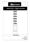
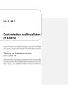
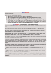
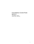
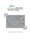
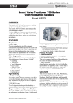
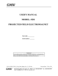
VS-3S, VS-3P, VS-3R
LiPoly-Controller
including
voltage converter,
electronic FET switch
uC-battery monitor
User Manual
1.
D e sign a n d V e r sions
This sm all dev ice cont ains t hree fu nct ions:
elect ronic FET securit y sw it ch ( not VS- 3R)
uC- bat t ery m onit or
v olt age conv ert er
VS- 3S and VS- 3P are t echnical ident ical but in different
pack ages. VS- 3S has a plast ic case and a carbon fiber
front panel. Size and m ount ings are sim ilar t o st andar d
serv os w hich m ak es it easy t o put it int o serv o m ount s.
VS- 3P com es in a heat shrink ing t ube and can be m ount ed
w it h double sided adhesiv e servo t ape. VS- 3R ist t he sam e
as VS- 3P but w it hout t he elect r onical sw itch.
2.
Fun ct io na l Pr inciple :
Many receiv ers, serv os and ot her elect ronic dev ices are
designed t o be pow ered w it h 4- cell NiCd bat t ery pack s.
Therefore t he m ax im um allow ed v olt age is 6 v olt s. The
usage of a 2- cell LiPoly bat t ery pack is not allow ed since it
has 7,4 Volt nom inal. This requires a v olt age conv ert er
w hich reduces t he LiPoly volt age t o t he low er
receiv er/ serv o volt age.
VS- 3S/ P/ R has a built - in v olt age regulat or w hich w ork s
w it h 2 or 3 LiPoly cells or 5 t o 7 MiCd/ NiMH cells. The
reduced out put v olt age can be adj ust ed bet w een 5 and 6
v olt s by t he user.
3.
Con ne ct ion:
VS- 3S/ P/ R has silicon cables for t h e bat t ery connect ion.
RED is t he posit iv e pole, BLACK is t he negat iv e pole.
Double- check t he correct connect ion. Rev erse connect ion
w ill dest roy t he device.
Mak e t he usual t ransm ission range t est before operat ing
y our m odel !
4.
V olt a ge Adj u st m e n t :
The out put v olt age can be adj ust ed w it h a sm all
pot ent iom et er. Connect a v olt age m et er t o t he out put
w ires and adj ust t he v olt age t o any v alue bet w een 5 and 6
v olt s. Usually t he best v olt age is 5,5 v olt s, w hich is set up
from t he fact ory . The out put volt age cannot be higher
t han t he bat t ery v olt age. When t he set t ing is done, put
som e glue on t he pot ent iom et er.
5.
V olt a ge Conv e r t e r
This LiPoly Cont roller has an ex t rem ely low - loss v olt age
regulat or. Even w hen t he bat t ery is alm ost em pt y it can
produce a st able out put v olt age. The qualit y of t he out put
v olt age depends m ainly on t he bat t ery qualit y and t he
w iring in y our m odel. Especially for digit al serv os t he
w iring m ust be done w it h t hick w ir es.
-
Use short cables bet w een bat t ery and VS- 3x and use
only good gold- plat ed plu gs.
Use only high current bat t eries lik e m odern LiPoly
cells and put as m any LiPoly cells in parallel as
required t o get sufficiant cur rent for y ou r m odel.
6.
Ele ct r on ic Sw it ch
VS- 3S/ P is equipped w it h a highly reliable elect ronic safety
sw it ch. I t is ident ical t o ou r w idly used ES- 2 and uses t he
advant ages of bot h, t he elect ronical and m echanical sw itch
in parallel.
7.
uC- Ba t t e r y M onit or
Monit oring t he v olt age of LiPoly cells is absolut ely
necessary . These cells can easily be dam aged if
discharged below 2,5 v olt s. Therefore t his dev ice has a
built - in bat t ery m onit or w hich m easures t he v olt age 100
t im es a second and st ores t he m inim um value du ring
operat ion of y our m odel.
A dual- colour LED show s t he st at us of t he bat t ery :
GREEN const ant light
Bat t ery full
GREEN blink ing
Bat t ery m ore t han ½ filled
GREEN/ RED blink ing
Bat t ery ½ filled
RED blink ing
Bat t ery less t han ½ filled ( charge ! )
RED const ant light
Bat t ery alm ost em pt y ( charge
im m ediat ely ! )
The bat t ery m onit or is set up by the fact ory t o a w arning
v olt age of 6 v olt s for operat ion w it h 2 LiPoly cells.
To adapt it t o y our m odel, a re- adj ust m ent is required
w hen it is m ount ed in t he m odel or w hen anyt hing has
been changed ( bat t eries, serv os ...) :
To adj ust t he bat t ery m onit or discharge y our bat t ery
com plet ely . Then charge about 15% of t he t ot al capacit y .
Then m ov e all cont rol st ick s ( m ov e all serv os) for 30
seconds. The LED should be j ust const ant ly ON in RED
color. This v alue can be adj ust ed w it h a pot ent iom et er, but
ONLY if t he pow er is sw it ched OFF ! Aft er m ov ing t he
pot ent iom et er, sw it ch ON again and t est t he new set t ing.
When t he set t ing is done, put som e glue on t he
pot ent iom et er.
8.
Ba t t e r y W a r n ing LED
VS- 3S/ P/ R has an ex t ernal 10m m ex t relem y bright red
LED. This LED light s and blink s lik e t he sm all LED on t he
dev ice. I t can be m ount ed in a good v isible posit ion of
y our m odel. When t his LED is blink ing, charging is
recom m ended. I f it is const ant ly ON, im m ediat e chargin g
is absolut ely necessary since t he bat t ery is em pt y .
Also t his w arning LED requires a correct set up of t he
bat t ery m onit or pot ent iom et er.
9.
Coolin g
Coling is not required under norm al operat ing condit ions.
For securit y reasons VS- 3x has a heat sink for ex t rem ly
condit ions. Do n ot cov er t his heat sink .
1 1 . M ou nt in g
VS- 3S is designed for serv o m ount s w hich are av ailable in
m any m odels. Use t he four rubbers and riv et s as usual for
serv o m ount s. The four holes are posit ioned t o be
com pat ible w it h JR/ Graupner and Fut aba/ Robbe servo
m ount s.
VS- 3P/ R are m ount ed w it h double sided adhesive t ape or
sim ilar. Tak e care for v ibrat ion dam ping w it h foam or
serv o t ape.
1 2 . Te ch nica l D a t a
Maxim um Current :
short peak current :
Bat t ery volt age:
regulated out put voltage:
bat t ery m onit or:
Warning- LED:
Weight VS- 3S:
Size VS- 3S case:
Weight VS- 3P/ R:
Gr??e VS- 3P/ R:
funct ional priciple:
1 0 . Posit ion of Pot e nt iom et e r s
V S- 3 S:
15 A ( for u sual load in m odels, not
perm anent load)
50 A
6 - 12 v olt s ( Cells: 2- 3 LiPoly, 5- 7 NiCd /
NiMH)
abt . 5 - 6 volts
dual- color- LED show s 5 bat t ery st at es
10m m ex trem ely bright
abt . 45 g incl. cables
38 x 20 x 25 m m ( LxWxH) ,
front panel 58 x 21,5 m m ( servo size)
abt . 35 g incl. cables
49 x 19 x 20 m m ( LxWxH)
disort ion free MOSFET technics ( no noisy
swit ching regulat or ! )
Ope r a t in g Con dit ions a nd Lim it a t ion s
Operat ion is per m it t ed only for use in R/ C m odels. Under
any circum st ances t he operat ion is not perm it t ed in
m anned aircraft s, m edical inst rum ent s or in any
environm ent s, in w hich an inst rum ent failure m ay cause
hum ans com e t o harm !
Dam aged or w et dev ices m ust not be operat ed. A
connect ion w it h a 230 V a.c. m ains is illegal. An operat ion
in elect rom agnet ic or elect rost at ic dist urbed places is not
adm issible.
V S- 3 P/ R:
I nst allat ion, operat ion and use of t his pr oduct cannot be
w at ched. Therefore t he user is responsible for t he correct
use of t he product . The product m ay only be t aken in
operat ion, if t he user underst ands and handles all risks
and dangers w hich can result from t he operat ion of t he
inst rum ent . The m anufact urer does not t ak e any adhesion
for personal inj u ries, dam ages t o propert y , losses or cost s,
w hich result from incorrect use or operat ion of t his product
or are connect ed in any w ay w it h it . That applies in
part icular t o claim s for dam ages, w hich w ere released by
failure or m alfunct ioning.
The legal w arrant y
ex cluded.
periods apply . All ot her request s
The product m eet s t he relev ant
guidelines and st andar ds.
and m andat ory EEC