1
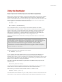
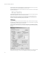
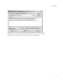
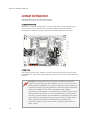
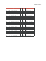
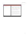
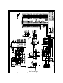
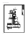
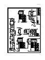
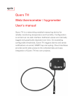
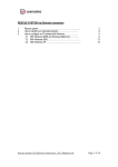
Ethernut Version 3.0 Hardware User`s Manual Manual Revision: 1.0 Issue date: November 2005 Copyright 2005 by egnite Software GmbH. All rights reserved. egnite makes no warranty for the use of its products and assumes no responsibility for any errors which may appear in this document nor does it make a commitment to update the information contained herein. egnite products are not intended for use in medical, life saving or life sustaining applications. egnite retains the right to make changes to these specifications at any time, without notice. All product names referenced herein are trademarks of their respective companies. Ethernut is a registered trademark of egnite Software GmbH. Contents About the Ethernut 3.0 Board . . . . . . . . . . . . . . . . . . . . . . . . . . . . . . . . . . . . . . .1 Ethernut Features . . . . . . . . . . . . . . . . . . . . . . . . . . . . . . . . . . . . . . . . . . . . . . .1 Block Diagram . . . . . . . . . . . . . . . . . . . . . . . . . . . . . . . . . . . . . . . . . . . . . . . . .2 LED Indicators . . . . . . . . . . . . . . . . . . . . . . . . . . . . . . . . . . . . . . . . . . . . . . . . .2 Serial Ports . . . . . . . . . . . . . . . . . . . . . . . . . . . . . . . . . . . . . . . . . . . . . . . . . . . .3 Ethernet Port . . . . . . . . . . . . . . . . . . . . . . . . . . . . . . . . . . . . . . . . . . . . . . . . . . .3 Expansion Port . . . . . . . . . . . . . . . . . . . . . . . . . . . . . . . . . . . . . . . . . . . . . . . . .3 Power Supply . . . . . . . . . . . . . . . . . . . . . . . . . . . . . . . . . . . . . . . . . . . . . . . . . .4 Watchdog Timer . . . . . . . . . . . . . . . . . . . . . . . . . . . . . . . . . . . . . . . . . . . . . . . .4 System Clock . . . . . . . . . . . . . . . . . . . . . . . . . . . . . . . . . . . . . . . . . . . . . . . . . .4 Flash ROM . . . . . . . . . . . . . . . . . . . . . . . . . . . . . . . . . . . . . . . . . . . . . . . . . . . .4 Static RAM . . . . . . . . . . . . . . . . . . . . . . . . . . . . . . . . . . . . . . . . . . . . . . . . . . . .4 EEPROM . . . . . . . . . . . . . . . . . . . . . . . . . . . . . . . . . . . . . . . . . . . . . . . . . . . . . .5 Configuration Jumpers . . . . . . . . . . . . . . . . . . . . . . . . . . . . . . . . . . . . . . . . . .5 Upgrading from Previous Ethernut Revisions . . . . . . . . . . . . . . . . . . . . . . .5 Quick Start . . . . . . . . . . . . . . . . . . . . . . . . . . . . . . . . . . . . . . . . . . . . . . . . . . . . . . .6 Prerequisites for Operation . . . . . . . . . . . . . . . . . . . . . . . . . . . . . . . . . . . . . . .6 Precautions . . . . . . . . . . . . . . . . . . . . . . . . . . . . . . . . . . . . . . . . . . . . . . . . . . . .6 Board Installation . . . . . . . . . . . . . . . . . . . . . . . . . . . . . . . . . . . . . . . . . . . . . . .7 Using the Bootloader . . . . . . . . . . . . . . . . . . . . . . . . . . . . . . . . . . . . . . . . . . . . . .9 TFTP Server . . . . . . . . . . . . . . . . . . . . . . . . . . . . . . . . . . . . . . . . . . . . . . . . . .10 Jumper Configuration . . . . . . . . . . . . . . . . . . . . . . . . . . . . . . . . . . . . . . . . . . . .12 Jumper Overview . . . . . . . . . . . . . . . . . . . . . . . . . . . . . . . . . . . . . . . . . . . . . .12 JTAG Port . . . . . . . . . . . . . . . . . . . . . . . . . . . . . . . . . . . . . . . . . . . . . . . . . . . .12 Hardware Expansion . . . . . . . . . . . . . . . . . . . . . . . . . . . . . . . . . . . . . . . . . . . . . .14 Expansion Port . . . . . . . . . . . . . . . . . . . . . . . . . . . . . . . . . . . . . . . . . . . . . . . .14 Troubleshooting . . . . . . . . . . . . . . . . . . . . . . . . . . . . . . . . . . . . . . . . . . . . . . . . .16 Schematic . . . . . . . . . . . . . . . . . . . . . . . . . . . . . . . . . . . . . . . . . . . . . . . . . . . . . .20 About the Ethernut 3.0 Board About the Ethernut 3.0 Board Low-ccost Ethernet capability can be added to many embedded applications. Since its introduction in the year 2000, Ethernut boards have been used to develop some of the most innovative products. Using the hardware, firmware, software and tools, developers have everything they need to develop leading networked devices rapidly and affordably. The board is well suited for application development in a wide range of applications. Some areas are: Networked sensors Remote monitoring equipment Alarm service providing Remote diagnose and service Industrial Ethernet applications Home and building control Ethernut Features Ethernut 3.0 is a small (80 x 100 mm) board combining Atmel's AT91R40008 RISC microcontroller with Davicom's DM9000E Ethernet controller. The main features are: ARM7TDMI RISC microcontroller with up to 75 MIPS throughput Full duplex IEEE 802.3 compliant 10/100 Mbps Ethernet controller with onboard RJ- 45 connector RS-232 at DB-9 connector with full handshake Multimedia Card Socket 4 MByte in-system programmable Flash ROM 256 kByte SRAM 512 Byte in-system programmable EEPROM 24 programmable digital I/O lines Real time clock with two alrams Three 16-bit timer/counters Watchdog timer for enhanced reliability LED indicators for power supply and Ethernet activity Single power supply DC 5-24V 1 Ethernut Hardware Manual Block Diagram The block diagram shows the main components. Definitely the most important part is the AT91R40008 microcontroller. It’s a quite complex chip and described in detail in Atmel’s AT91R40008 data sheet. Almost all I/O ports are routed to the Ethernut expansion port, a 64-pin connector, which can be used to add custom hardware like the Medianut MP3 decoder with LCD interface. The microcontroller provides two UART channels, which are routed to the onboard RS-232 level shifters. A Xilinx CPLD is used to implement the glue logic. While Ethernut’s software offers serveral bootloader capabilities over RS-232 or Ethernet, program code is initially uploaded through the JTAG interface. The connector layout conforms to Atmel’s 10-pin AVR JTAG interface. a WARNING: Ethernut 3 uses the same JTAG connector layout as its predecessors Ethernut 1 and 2, which is not compatible with the standard ARM 14-pin or 20-pin connectors. A cable adapter will be required to attach standard ARM JTAG adapters. 2 About the Ethernut 3.0 Board LED Indicators The Ethernut 3.0 board is equipped with four LEDs. Two of them are integrated in the reset switch, a red LED to indicate power supply and a green LED, which is available for user applications. Another two LEDs are integrated in the RJ45 Ethernet connector. The green LED indicates the network link status and is lit when the link status is OK. The yellow LED indicates receive and transmit activity from and to the network. Serial Ports Ethernut provides an on-board DB-9 male connector for RS-232 serial communication. IC6 is used to convert the required voltage levels for RS-232 from the 5V power supply. Any of the two serial interfaces of the microcontroller can be routed to the RS232 connector via selection registers within the CPLD. In the default configuration the first interface (UART0) is routed to the RS-232 connector while the second interface (UART1) is not used. Ethernet Port Ethernut provides an on-board modular RJ-45 connector with an integrated 100/10Base-T transformer/filter for its twisted pair Ethernet port. This port is connected to the Davicom DM9000E Ethernet controller. The interface supports the maximum cable length of 100 meters between the Ethernet board and a hub or switch. Expansion Port Add-on boards can be added to the expansion port. These boards may contain simple I/O circuits driven by the Ethernut board, or may be equipped with their own CPU, using the Ethernut board as an Ethernet I/O processor only. 3 Ethernut Hardware Manual Power Supply The I/O logic of the Ethernut 3 board is driven by a 3.3V power supply, while the CPU core runs at 1.8V. The board provides its own voltage regulators (IC8 and IC9). It only requires an unregulated power supply of DC 5-24V with a minimum current of 200 mA. Two different methods may be used to connect an external power supply. 1 A standard 2.1 mm barrel connector. This input is protected by a fuse (F1), a fast transient voltage suppressor (D1) and a rectifier bridge (D4, D5, D6 and D7). 2 The DC signal is routed to the Ethernut expansion connector to either supply add-on boards or to receive power supply from an add-on board. This input is unprotected. As soon as power is attached to any of the inputs, the red LED in the reset switch will lit. Watchdog Timer Software bugs, temporary hardware failures caused by electrical transients or interference and many other problems might cause the system to malfunction. The AT91R40008 microcontroller (IC1) provides an on-chip watchdog timer, which forces a system reset, if the application program fails to periodically update this timer. System Clock Driven by a 25 MHz crystal, all high speed clock signals are generated by a programmable clock generator (IC5). The microcontroller clock is configured at 73.728 MHz, while the Ethernet Controller runs from a 25 MHz clock signal. Two additional clocks are available for the CPLD, but are not used in the standard configuration. A second crystal (Y2) with 32.768 kHz drives the on-board RTC chip (IC7). a WARNING: Note, that changing any frequency will alter the Ethernut board's EMC characteristics and require re-testing. Static RAM The AT91R40008 CPU provides 256 kBytes of high speed 32-bit on-chip SRAM, which can be used for code execution and data storage. Flash ROM The AT91R40008 provides no on-chip flash memory. An external flash memory chip had been added to permanently store program code and read-only data. This memory is organized as 4 Mb x 8 bits and can be (re-)programmed by the CPU. To achive this, a simple flash utility is programmed into the CPU RAM and started via the JTAG interface. This utility will then communicate via the JTAG adapter and burn the received flash image into the external memory chip. 4 About the Ethernut 3.0 Board EEPROM The Xicor X1226 Realtime Clock/Calendar chip has a integrated 512 Byte EEPROM, typically used for configuration data storage. This chip is accessed via a TWI (I2C) interface. However, as the CPU doesn’t contain any TWI hardware, software bit-banging must be used. Configuration Jumpers In opposite to its predecessors, almost all configuration settings are done in the CPLD (IC3). Only a single jumper area is left to configure the JTAG chain. For historical reasons this jumper is named JP5. Jumpers JP1 to JP4 do not exist. Upgrading from Previous Ethernut Revisions Ethernut has undergone many changes since its initial release in the year 2000, but board dimensions and positions of main connectors remained unchanged. Also, the software still supports all previous Ethernut Boards, even revision 1.1 with the ATmega103 microcontroller, which is no longer in production. However, there are a few things to consider. The most important change to notice is the different CPU used on Ethernut 3. Thus you can’t use programming adapters shipped with previous starter kits, because Ethernut 3.0 needs a specific JTAG adapter for an ARM CPU. SPI programming is not supported. Never plug your SPI adapter into Ethernut 3.0 programming socket. Also note, that the ARM7TDMI used on Ethernut 3 has a different I/O port layout compared to the AVR CPUs used on previous boards. Care has been taken to keep the expansion port as compatible as possible. 5 Ethernut Hardware Manual Quick Start This chapter will help you quickly set up and start using the Ethernut board. Prerequisites for Operation The following items are necessary to run the Ethernut board: A standard PC equipped with Linux or Windows, an available serial COM port and a twisted pair Ethernet adapter card. Terminal emulation software, such as TeraTerm or Hyperterminal. TFTP server, such as TFTPD32. An unregulated power supply matching your local mains. It should supply DC 5-24V, 200 mA minimum, on a standard 2.1 mm barrel connector. Two straight-through twisted pair cables together with 100 or 10 Base-T hub or switch or a twisted pair cross cable, if you don't got a hub or switch. The following items are included in the Ethernut Starter Kit: A JTAG compatible programming adapter. A crossed serial communication cable with DB-9 female connector at both ends. It is further assumed, that you got some basic knowledge about digital hardware and TCP/IP networking. This manual will not present any of these basics, but you can find excellent books or web resources about these topics. Precautions Born out of an Open Source Project, the Ethernut board is a commercial product, from which you expect some kind of fail safe operation. But also keep in mind, that a bare electronic circuit is a fragile product, which demands careful handling. In the first place learn how to avoid problems caused by electrostatic discharge. 6 Quick Start Board Installation 1 Remove the board from the antistatic bag. Visually inspect the board to verify that it was not damaged during shipment. Do not use the antistatic bag as a underlying pad for Ethernut, because it’s electroconductive. Put the board on a wooden surface or simply on a piece of paper. Plastic surfaces may be harmful because of electrostatic discharge. a WARNING: As with all computer equipment, the Ethernut board may be severely damaged by electrostatic discharge (ESD). Be sure to take proper precautions before removing the Ethernut board from the antistatic bag. Never pass the board from one person’s hand to another. 2 Connect Ethernut`s DB-9 RS232 port to an available COM port using the serial cable. 3 Use one twisted pair cable to connect Ethernut's RJ-45 connector to the hub or switch and the other twisted pair cable to connect the hub or switch with the network adapter in the PC. If you are not using a hub or switch, then directly connect the Ethernut board with the PC’s network adapter using a twisted pair cross cable. 4 Connect the power supply to the barrel connector on the Ethernut board. The Ethernut board is equipped with its own rectifier bridge and voltage regulator. Therefore the polarity of the barrel connector isn't important. a WARNING: The power supply should not be plugged into an electrical outlet before connecting it to the Ethernut board. 5 Apply power to the Ethernut board by connecting the power supply to an electrical outlet. When the board is powered up, the red power LED should go on. 6 Start the terminal emulation program at 115200 baud, no parity, 8 data bits, and 1 stop bit. Disable hardware (RTS/CTS) and software (XON/XOFF) flow control. Baudrate The baudrate of the Ethernut board is specified by the CPU clock (IC5, 73.720 MHz by default) and a baudrate divisor ranging from 0 to 65535. The actual baudrate can be calculated by baudrate = CPU clock / (16 * divisor) 7 Ethernut Hardware Manual 7 Reset the Ethernut board by depressing and releasing the reset switch located near the MMC socket. Hold down the spacebar on the terminal emulation program and wait until the BootMon welcome message is displayed. See the next chapter for a detailed description of the BootMon program. 8 Bootloader Using the Bootloader Using the preloaded BootMon firmware to load Ethernut applications. When using a terminal emulation program like described in the previous chapter, hold down the space bar on the PC keyboard and press and release the reset button on the Ethernut board. This is the tiny push button with the red LED at the board’s edge near the MMC socket. After some seconds the following output should appear in the terminal emulation window: BootMon 1.0.1 MAC address (000698300000): Your preloaded version may be higher and the MAC address will differ. The bootloader is resident, which means, that it is started each time you apply power to the board or press the reset button. However, it will normally work silently in the background, using any previously entered configuration. To change this configuration, a space character must be send to the serial port immediately after starting. Let’s enter a new configuration now. The MAC address should have been correctly set. Press enter to confirm this parameter. A MAC address, also referred to as the hardware or Ethernet address is a unique 48 bit number assigned to every Ethernet node. The upper 24 bits are the manufacturer's ID, assigned by the IEEE Standards Office. The ID of Ethernut boards manufactured by egnite Software GmbH is 000698 hexadecimal. The lower 24 bits are the board's unique ID assigned by the manufacturer of the board. Boards produced by egnite do have a unique ID, which is written on the board. BootMon will ask for the IP Address of the board. IP address (0.0.0.0): If your network provides a DHCP service, you can leave the IP address at all zeros. However, for a first test it is recommended to specify an individual address, which fits to your local network. For example, let’s assume, that your PC got IP address 192.168.0.3, than 192.168.0.4 should work, provided that no other device in your network is using this address. Enter the individual IP address and press enter. BootMon will prompt for the network mask. Net mask (255.255.255.0): You must use the same network mask as it is used with your PC. In general, all nodes within a local IP network must have the same network mask. After entering a network mask, BootMon asks for a default route. Default route (0.0.0.0): This should be the IP address of your router, used to connect to the Internet. This information is only required, if the Ethernut board will be accessed from or will 9 Ethernut Hardware Manual access another node via the Internet. For now we can leave this entry at 0.0.0.0, which means, that no Internet gateway should be used. Finally BootMon will ask for the TFTP Server IP and for the name of the image to load from this server. TFTP IP (192.168.192.2): TFTP Image (threads.bin): The IP address should be the one of your PC. The name of the image is actually the Ethernut Application we will load into the board. After pressing enter to confirm the TFTP image name, all parameters will be stored in non-volatile EEPROM memory and BootMon will immediately try to load the specified file from the specified TFTP server. TFTP Server There are a number of TFTP servers available, many of them are free of charge. For Windows, TFTPD32 is a good choice. With Linux, a TFTP daemon is typically installed already, it just needs to be activated. The following screenshot shows a sample configuration of TFTPD32. The Base Directory point to the directory that contains the precompiled Nut/OS application binaries. After pressing the reset button, BootMon will request the binary image from the TFTP server running on your PC. On TFTPD32 the following should appear. 10 Bootloader The sample contained in threads.bin demonstrates NUT/OS multithreading capabilities and outputs a series of Hs, Ms and Ls. You may want to check the source code of this sample now or try some of the other samples. 11 Ethernut Hardware Manual Jumper Configuration Adapting Ethernut to specific requirements. Jumper Overview Almost any available configuration is done in the CPLD except setting up the JTAG chain. For this, JP5 is used. The picture below shows the default configuration, where the JTAG connector is directly attached to the CPU. JTAG Port The angled, boxed 10-pin header connector allows serial programming of the AT91R40008 as well as the CPLD without physical removal of the chips from the system. a WARNING: Unlike previous board revisions, Ethernut 3.0 doesn`t support programming with ISP Adapters. Thus, you can`t use one of the programming adapters from previous Ethernut boards. Make sure to either use the programming adapter of the Ethernut 3.0 Starter Kit, Atmel`s ATJTAGICE or any other compatible JTAG adapter. Connecting an ISP adapter to the Ethernut 3.0 JTAG connector will at least blow the board`s fuse or in worst cases destroy your Ethernut. Also note, that the adapter from the Ethernut 3.0 Starter Kit provides both, ISP and JTAG programming, using two clearly marked cables. Never plug the ISP cable into the Ethernut 3.0 programming connector. Always use the cable, which is clearly marked with the label “JTAG”. 12 Network Configuration JP5 Jumper JP5 routes the JTAG signals to the AT91R40008, if pins 1 and 2 and pins 5 and 6 are shortened. JP5 Routing the JTAG interface to the CPLD is provided by shortening pins 1 and 3, 4 and 6, 7 and 8 as well as pins 9 and 10. However, you need a special Xilinx adapter for programming the CPLD via JTAG. JP5 As an alternative, the Ethernut is able to program its own CPLD. The required jumper configuration is shown on the left. 13 Ethernut Hardware Manual Hardware Expansion Ethernut and custom hardware. Many applications will do just fine with nothing else than the Ethernut or external hardware may be connected to the RS-232 port. However, if more is required, the Ethernut expansion port is the first choice to add custom designed hardware. Expansion Port Add-on boards can be added to the expansion port. This connector contains partial CPU data and address bus, memory read/write signals, digital I/O ports, reset signal and power supply. Nearly all microcontroller pins are available at the expansion port connector, providing an interface with several features like 2-wire interface (I2C) or counter inputs and outputs. It is strictly recommended to consult the AT19R40008 data sheet before attaching hardware to the expansion port. Many signals are routed through the CPLD and may be redefined by reprogramming this chip. Although available at the connector, some signals are used internally by Ethernut and can’t be used by external hardware. Carefully check the schematic. The following table lists the expansion port’s pin assignment. 14 Hardware Expansion Pin Signal Description 1 VCC3 Regulated +3.3V 3 NC Not connected 5 GND Signal ground 7 GND Signal ground 9 MR\ Reset input 11 NC Not connected 13 RD\ Memory read signal 15 D0 Data bus bit 0 17 D2 Data bus bit 2 19 D4 Data bus bit 4 21 D6 Data bus bit 6 23 A0 Address bus bit 0 25 A2 Address bus bit 2 27 A4 Address bus bit 4 29 A6 Address bus bit 6 31 A8 Address bus bit 8 33 A10 Address bus bit 10 35 A12 Address bus bit 12 37 A14 Address bus bit 14 39 P15 UART 0 Receive 41 P13 UART 0 Clock 43 P9 External IRQ0 45 P11 External IRQ2 47 P0 Timer 0 Clock 49 P2 Timer 0 I/O B 51 P4 Timer 1 I/O A 53 P6 Timer 2 Clock 55 P17 GPIO 57 P22 UART 1 Receive 59 P23 GPIO 61 P19 GPIO 63 NC Not connected Pin Signal Description 2 VCC3 Regulated +3.3V 4 NC Not connected 6 GND Signal ground 8 GND Signal ground 10 DC Unregulated supply 12 NC Not connected 14 WR\ Memory write signal 16 D1 Data bus bit 1 18 D3 Data bus bit 3 20 D5 Data bus bit 5 22 D7 Data bus bit 7 24 A1 Address bus bit 1 26 A3 Address bus bit 3 28 A5 Address bus bit 5 30 A7 Address bus bit 7 32 A9 Address bus bit 9 34 A11 Address bus bit 11 36 A13 Address bus bit 13 38 A15 Address bus bit 15 40 P14 UART 0 Transceive 42 P8 Timer 2 I/O B 44 P27 Chip select 3 46 P12 Fast IRQ 48 P1 Timer 0 I/O A 50 P3 Timer 1 Clock 52 P5 Timer 1 I/O B 54 P7 Timer 2 I/O A 56 P16 GPIO 58 P21 UART 1 Transmit 60 P20 UART 1 Clock 62 P18 GPIO 64 NC Not connected 15 Ethernut Hardware Manual Troubleshooting 16 Problem BootMon produces garbage output and the yellow LED at the RJ45 goes on after a few seconds. Solution BootMon was unable to detect a space characters at the required baudrate. The terminal emulator may use a wrong baudrate not send any characters because of handshake settings or other RS-232 communication issues. The red LED does not go on when applying power. The fuse may be blown. Remove any kind of attached hardware and remove all jumpers. Make sure the board is placed on a non conductive surface like a piece of paper. Replace the fuse (0.6A superfast) and supply the board via the barrel connector J2 only with not more than 24V DC. Best use a lab power supply with current control and carefully increase the voltage starting from 3V. The board should not draw more than 150 milliamps. The green LED at the RJ45 connector does not go on after pressing the reset button. The green LED will go on only if Ethernut is connected to an Ethernet network and the Ethernut software properly initialized the LAN controller hardware on the Ethernut. Load the board with BootMon image via JTAG. Replace the Ethernet cable and try the same connection with your PC to make sure that the network link is working. Troubleshooting Problems Solution Ethernut doesn’t respond to pings. The yellow LED does not go on. Configuring TCP/IP looks generally simple after one has understood the principle, but may still become confusing under some circumstances. For example, changing Ethernut’s MAC address can disable a link, which had been running fine before the change. This happens, because the PC remembers the MAC/IP relations for some minutes. Check your configuration again. Make sure, that Ethernut and the PC are located in the same network, sharing the same IP mask and network IP address. If you don’t know what all this means, check the WWW for some excellent TCP/IP tutorials. 17 Ethernut Hardware Manual Sick Ethernuts Is there still life in it? Our warranty scheme is simple. All boards have been extensively tested before shipment and we feel responsible, that it continues to work reliable after passing it to you. If the trouble shooting guide doesn’t help or if it results in the conclusion, that your Ethernut is broken, you should send an email to [email protected], including the following information: Ethernut Revision, printed on the back side of the board. MAC address of your Ethernut, written on top of the board and on the invoice. BaseMon output, if applicable. Or software revision you’re using, noted on the first page of the API documentation. Description of your problem. You may keep it simple, we may request details later. Please understand, that we are not able to provide any warranty, if you destroyed the board because of ignoring our ESD precautions advises or attaching badly designed hardware. In such cases we may ask at least for a refund of our shipping costs. Anyway, whatever happened, we will do anything possible to revitalize your Ethernut. Or, if it finally passed away, let it rest in peace and send a replacement back to you at the least possible costs. 18 19 Ethernut Hardware Manual 20 Schematic 21 Ethernut Hardware Manual 22 Schematic 23 egnite Software GmbH Erinstr. 9 44575 Castrop-Rauxel Germany Phone +49 (0)23 05-44 12 56 Fax +49 (0)23 05-44 14 87 Email [email protected] http://www.egnite.de http://www.ethernut.de