1
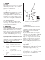
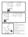
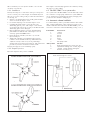
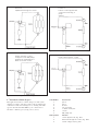
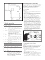
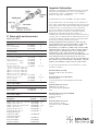
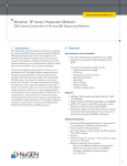
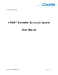
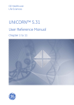
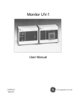
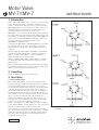
Motor Valve
MV-7/IMV-7
INSTRUCTIONS
1. Introduction
Motor Valves MV-7/IMV-7 are a 3-position, 7-port motorized
valves designed to he used as automatic sample injection
valves or system valves. The valves have 3 positions: LOAD,
INJ, WASH. The port communications for these positions are
illustrated in Fig I. A channel plate inside the valve body is
rotated to line-up the various ports on the valves.
MV-7/IMV-7 are controlled from the liquid Chromatography
Controller LCC-500, LCC-500 Plus, LCC 500 CI or LCC-501
Plus, which can control up to 6 Motor Valves MV-7/IMV-7 as
well as selection valves MV-8/IMV-8. The Motor Valves can
also be operated from controlling software such as
UNICORN™ or FPLCdirector™.
Combining the MV-7/IMV-7 and MV-8/ IMV-8 (8-port) valves
provides automatic flow control for multiple or repeated
sample injections, column and solvent switches and fraction
collection.
The main different between MV-7 and IMV-7 is the diameter
of the flow channels. The diameter of the flow channels for
MV-7 is 0.6 mm and for IMV-7 is 1.2 mm, which allows
higher flow rates at lower back pressure.
MV-7 is normally used in FPLC™System. IMV-7 is normally
recommended for BioPilot™System but can also be used in
FPLC System.
In this manual the LCC-500, LCC-500 Plus, LCC-501 CI and
LCC-501 Plus will be referred to as the controller. Only when
diffrences appear will specific names be used.
2. Unpacking
Please check delivery against the packing list.
3. Description
3.1 Functional design
Motor Valve MV-7/IMV-7 consists of two main parts, the
housing which encloses the motor and the electronics and the
valve body with the central core. The central core can be
rotated 360° inside the housing but when controlled from the
controller the shortest way to the next position is always
chosen. This means that the valve only rotates a maximum of
180° inside the housing. As the core in turned by the motor,
flow channels connect two peripheral ports on the valve body
(Fig. 1), allowing clear liquid paths. The peripheral port
numbers are marked on the valve body directly above each
port. If used as an automated injection valve, the three valve
positions correspond to the following operations:
LOAD – the sample loop is filled, INJ – the sample is applied
to the column, WASH – solvent change-over can be performed
without disconnecting the column from the system.
Valve switching is controlled from the controller by reading
the actual position of the valve using signals from a code plate
within the valve housing. The programmed commands from
the control unit cause the motor to run until the valve has
reached the desired position.
56-1153-36
Edition AD
Fig. 1. Three operating positions of the Motor Valve
MV-7/IMV-7.
3.2 Specifications
MV-7
Maximum
operating pressure:
Back pressure
at 1000 ml/hr:
Back pressure
at 6000 ml/h:
Wetted material:
Angle of rotation:
Dead volume
between ports:
Diameter of
flow channel:
Motor:
Connector:
IMV-7
5 MPa (50 bar, 710 psi)
2 MPa (20 bar, 285 psi)
0.3 MPa (3 bar, 45 psi)
–
–
PEEK + 20% PTFE
360°
0.02 MPa (0.2 bar, 2.8 psi)
PEEK + 20% PTFE
360°
ports 1-2
7.0 µl
2-3
ports 2-4
3-5
4-6 8.3 µl
5-7
6-7
1-7
ports 1-2
2-3
ports 2-4
3-5
4-6
2
ports 5-7
6-7
1-7
0.6 mm
24 V DC
D-type, 9 pin on cable
1.2 mm
24 V DC
D-type, 9 pin on cable
6.0 µl
10 µl
20 µl
For complete description of pin configuration see Section 7, Remote connection.
3.3 Chemical resistance
The valve body in contact with the solvent is made of PEEK
+ 20% PTFE. This is resistant to organic solvents and salt
buffers commonly used in a biochemical laboratory.
The valve can be used in a pH range of 2-13. If very strong
acids (pH <2) or bases (pH >13) are used, the valve should be
rinsed immediately afterwards.
Fig.2. Motor Valve MV-7 mounted onto a chromatography
rack.
4. Installation
4.1 Mounting the MV-7/IMV-7
The valve is fixed in place by screwing the support rod into
the valve body and attaching the road to a laboratory rack.
Mount the valve so the valve body is facing down.
When mounting valves into an automated FPLC System, it is
recommended to use the Chromatography Rack (Code No.
18-1031-75). The chromatography rack is supplied with a
number of laboratory rods and clamps which makes the
mounting of valves and other accessories simple and
convenient. (Fig. 2).
To mount the valve in the BioPilot System, please refer to the
BioPilot System User Manual.
4.2 Tubing
A tubing connection consists of three parts: flanged tubing,
nipple and nipple screw. (Fig. 3). Capillary tubing for FPLC
System with 0.5 mm i.d. (Code No. 19-7477-01) and for
BioPilot System with 1.2 mm i.d (Code No. 19-4370-01) are
supplied in two meter lengths and can be cut to any appropriate length.
For flanging, the Flanging/Start Up Kit, 120 V (Code No.
19-5079-01) or 220 V (Code No. 19-5090-01) and Flanging/
Start Up Kit for BioPilot 120 V, Code No. 18-4603-70 or 220
V, Code No. 18-4603-71 is necessary.
If you are using tubing other than that supplied, the flange
should have a flat, smooth surface and a diameter of approx.
3 mm.
When connecting the tubing to the valve ports, finger tighten
the tubing connectors into the valve body and the turn them a
further 45° with the plastic wrench supplied.
Note: Do not use standard wrenches to tighten the tubing
connectors. Do not overtighten the tubing connectors,
they are designed to seal up to 100 bars when flanged
properly. If the connector leaks after it has been
tightened with the plastic wrench, check the flange and
make a new one if needed.
Fig.3. Tubing connection.
4.3 Assorted loops and Superloop
Supplied with the Motor Valve MV-7/IMV-7 is a set of sample
loops (25, 50, 100, 200 and 500 µl). Sample loops 1 ml and
2 ml can be ordered as accessories. If volumes larger than 2 ml
will be injected, a 10 ml or 50 ml Superloop should be used.
A 150 ml Superloop is available for use with BioPilot System.
The Superloop is an accessory which allows large sample
volumes to be applied via an MV-7/IMV-7 valve without
unnecessary sample dilution. It is used in the same way as a
large sample loop, but avoids the tailing which results when
using a very large sample loop. Examples of how to inject
samples using the sample loops and/or Superloop are given in
Section 6, Application.
4.4 Connection to the controller
After mounting the Motor Valve MV-7/IMV-7 connect the
valve to the controller by plugging the D-connector into one
of the of the sockets on the rear panel if the controller marked
VALVE 1-6.
4.5 Valve position guide
The self-adhesive sticker which is supplied with the valve, may
be attached to the valve housing to provide a handy reference
to the connection scheme.
5. Operation
5.1 Principle
Valve switching is controlled from the controller or controlling
software either by manual settings or within programmed
methods. During a method run, a valve is switched at a
programmed time or volume, or by the monitor signal i.e.
when it passes a programmed threshold.
5.2 Programming
Allowed positions for the Motor Valve MV-7/IMV-7 are 1, 2
and 3. These numbers correspond to the positions LOAD, INJ
and WASH shown in Fig. 1. The home position for the valve
is always position 1 (LOAD). If the valve has not been
activated manually or within a programmed method, the valve
is in its home position.
If positions other than those described above are
programmed, the controller will give a check code and the
operation cannot be performed. The programmable function
which is used when controlling the MV-7/IMV-7 from the
controller is described in the next section.
5.2.1 Function VALVE POS.
To activate a valve MV-7/IMV-7, enter the valve number
corresponding to the socket number on the rear panel of the
controller, together with the position number. For example,
when programming a valve connected to the socket VALVE 2,
to switch to position 3 enter VALVE POS. 2.3.
6. Applications
6.1 Automatic sample injection
Automatic sample injections can be performed with the Motor
Valve MV-7/IMV-7 using either a sample loop or Super loop.
In both cases the sample is loaded with a pump. The sample
can also be introduced manually into the sample loop or
Superloop using the injection fill port supplied. Different port
connections on the MV-7/IMV-7 are used depending on how
the sample is introduced. Detailed descriptions on the port
connections that should be used are given in the following
sections.
6.2 Automatic sample injection using sample loops
6.2.1 Installation
To prepare a valve for connection to a system, you need
different tubings attached to each port. Each port numbers, its
system connection and tubing type are giving below.
Port No. Connects to
Tubing
1
Column
Screw tubing from the top of the column into
port 1.
2
Sample loop
or Superloop
(between ports
2 and 6)
Various types depending on desired volume.
Flange and tubing connectors on both ends.
3
Sample pump,
e.g. peristaltic
pump
The inlet of the pump is connected to port 3.
4
Sample
Use narrow tubing (o.d. 1.8 mm, i.d. 0.5 mm)
to minimize dead volumes.
5
Waste
Use tubing (o.d. 1.8 mm, i.d. 1.1 mm), with
flange and tubing connector on one end.
6.
Sample loop
or Superloop
(between ports
2 and 6)
See port 2.
7
Pump
The outlet from the pump is connected to port 7.
Flange and tubing connectors on both ends.
Fig.4. Port connections when using the MV-7/IMV-7 as an
automatic injection valve with a sample loop.
Fig. 4. shows the complete set-up. When the valve is connected
to the system, it is ready to be used as an injection valve.
6.2.2 Sample injection
For first time use, flush out the entire valve with water or
buffer.
Position 1, LOAD
In this position the column is equilibrated. When ready to
load a sample onto the column, start the pump and fill the
sample loop. The loop should be completely loaded.
Position 2, INJECT
After the loop has been loaded, the sample is injected by
setting the valve in this position. After 3 to 5 loop volumes,
return to position 1, LOAD.
Together with one Motor Valve MV-8/IMV-8, the MV-7/IMV7 can be used for automatic sample injection of up to 8
samples. Fig. 5. illustrates a standard set-up for automatic
sample injection using one MV-8/IMV-8 valve. When two
MV-8/IMV-8 valves are used, the number of samples can be
increased to 15, see Fig. 6. If rinsing is required between
sample injections, reduce the number of sample tubes to 7
(when using one MV-8/IMV-8) and have the rinse eluent in
the first tube. Rinsing the sample loop is performed when the
Motor Valve MV-7/IMV-7 is in position 1 (LOAD).
6.2.3 Changing pump solvents
Position 3, WASH
This position is used when it is necessary to change solvents in
the pump or when synchronizing the pumps (i.e. functions
WASH and SYNC in the controller). The solvent bypasses the
column by flowing directly from the pump to waste.
6.3 Automatic sample injection using Superloop
If applying large volume of diluted sample onto the columns, a
Superloop should be used. There are two versions of the
Superloop, holding up to 10 ml or 50 ml samples. A 150 ml
Superloop is available for use with BioPilot System.
A Superloop can also be used in multi-dimensional separation
schemes where fractions from one column are automatically
transferred via the Superloop to another column by column
switching. (See figure 5 and 6).
Fig. 5. A Motor Valve MV-7/IMV-7 used in combination with a MV-8/IMV-8 valve for automatic sample injection.
Fig. 6. A Motor Valve MV-7/IMV-7 used in combination with two MV-8/IMV-8 valves for automatic sample injection.
6.3.1 Installation
When using a Superloop instead of sample loop, the installation is identical with the exception that the sample is
introduced via port 3 using a peristaltic pump or, when
working with column switching, the Superloop is loaded with
the fraction from another column via port 3 (see Fig. 7).
6.3.2 Sample injection
The sample injection procedure is identical to that used when
injecting samples with sample loops.
Position 1, LOAD
The sample is loaded into the Superloop by a peristaltic pump.
Position 2, INJECT
In this position sample is applied to the column. Depending
on the experimental conditions, the loaded sample can be
injected all at once or in smaller volumes. For smaller
volumes, set the valve position 1 LOAD after the desired
volume has left the Superloop.
6.4 Manual sample injection
Fig. 7. Port connections when using a MV-7/IMV-7 as an
automatic injection valve with the Superloop.
The sample can also be manually injected into the sample loop
or Superloop using the Injection fill port supplied. The sample
loop can be partially or completely loaded with a syringe.
We recommend you to use injection needles, o.d. 0.55 mm
(Code No. 18-7143-01).
The sample is automatically applied to the column by setting
the valve to position 2 INJ.
6.4.1 Installation
6.5 The MV-7/IMV-7 as a system valve
The injection fill port is connected to valve port 3 and port 4
serves as a waste port for the sample. To install the injection
fill port, proceed according to the procedure described below,
see also Fig. 10.
1. Check to see that the Teflon ring, needle guide and inner
sleeve are inside the adaptor screw.
2. Loosen the adjusting screw from the adaptor screw.
3. Carefully thread the adaptor screw into the valve
distributing plate at port 3. The adaptor screw must be
screwed into the valve body correctly or the threads in the
distributing plate can be damaged.
4. Finger tighten the adaptor screw into the distributing
plate. Make sure that the end of the adaptor screw is
seated up against the PEEK surface.
5. Insert the injection needle (0.55 mm o.d.) into the
injection fill port.
6. Tighten the adjusting screw until the Teflon ring has
formed a seal around the needle´s tip. When the seal is
adjusted correctly, it feels as if you are penetrating a
septum at the end of the injection fill port. The seal should
provide easy insertion and removal of the needle.
The injection fill port is now installed properly.
As a system valve, the MV-7/IMV-7 can automatically connect
two columns to a single pump and detector system. With this
set-up, Column I or Column II is selected by changing valve
positions from 1 LOAD to 2 INJ (Fig. 8).
6.4.2 Sample injection
Inject the sample in valve position 1 LOAD.
6.6 Automatic column backflush
To reduce build-up of micro-particulate matter in the column
inlet, routine backflushing of the column is strongly recommended. The table below describes the MV-7/IMV-7 port connections for automatic column backflushing (see Fig. 9 a, b, c).
Port Number
1
2
3
4
5
6
7
Connected to
column
monitor
port 4
port 3
waste
column
A/B pump outlet
Valve position
1
2
3
Function
down-flow through the column. Fig- 9 a.
upward flow through the column, Fig. 9. b.
changes solvent without altering the
direction of flow, Fig. 9 c.
Position 1
Down flow through the column.
Fig. 9 a. Down-flow through the column.
Fig. 8. The MV-7/IMV-7 as a system valve.
Position 2
Position 1
Upward flow through the column.
Permits column by-pass with
continuous monitoring of
pump
effluent.
Fig. 9 b. Upward flow through the column.
Fig. 10 a. Column by-pass flow.
Position 3
Position 2
Permits automatic solvent
changeover in the A/B pumps,
pumping the liquid directly to
waste not via the column.
Down flow through the column.
Fig. 10 b. Down-flow through the column.
Fig. 9 c. Solvent changes without altering the flow direction.
6.7 Automatic column by-pass
This application monitors solvent change-over and system
cleaning procedures. A monitor and recorder document and
confirm successful solvent changeover or cleaning. The table
opposite describes the MV-7/IMV-7 port connections for
automatic column by-pass (see Fig. 10 a, b, and c).
Port Number
1
2
3
4
5
6
7
Valve position
1
2
3
Connected to
port 2
port 1
monitor
not connected
1 MV-8 central port
column
A/B pump inlet
Function
column by-pass flow, Fig. 10 a.
down-flow through the column, Fig. 10 b.
solvent change-over, Fig 10 c.
8. Valve maintenance and repair
Position 3
Permits solvent changeover.
The valve can be disassembled for cleaning or solvents may be
pumped through to wash it out. Suitable cleaning solvents are
water, ethanol, 75% CH3COOH, 0.2 M NaOH and
detergents. When using cleaning agents other than water,
always rinse the valve with water as the final step.
8.1 Disassembly
Fig. 10 c. Solvent change-over
7. Remote connection
Active
Pin voltage
Function
1
+24 V
Supplies power to the motor and relay. For
power consumption see pins 2 and 6.
2
0
Controls the valve rotation (Sink min. 30 mA,
for clockwise rotation.)
3
0-1.5 V
indicates the valve position match. When
active (in position) the valve position can be
read on pins 8 and 9 (address pins).
4
-
Signal ground voltage reference for the
signals listed in this table.
5
+5 V
Supplies power to the LEDs in the valve. Min.
80 mA.
6
0
Controls the start/stop function of the motor.
Sink min. 1 A to start, then approx. 0.3 A
while running. Short circuit to pin 1 to stop.
8
min. 3 V Indicates the valve address BIT 1. See also
table below.
9
min. 3 V Indicates the valve address BIT 0. See also
table below.
Codes for the 3 valve positions are shown in table below.
Position
Address
BIT 1
BIT 0
Position match
1
2
3
0
1
1
1
0
1
0
0
0
1 = 3-5
0 = 0-1.5 V
Note:
The motor Valve MV-7/IMV-7 is designed to be
controlled by the controller. If the MV-7/IMV-7 will
be controlled from other equipment (e.g. a
microprocessor) a 10 kΩ pull-up resistor to +5 V
must be connected to pins 3, 8 and 9 of the Dconnector of the MV-7/IMV-7.
See Figure 11.
1. Set the valve to position 1 LOAD before disconnection it
from the controller.
2. Remove the four Allen head screws on the bottom of the
valve. Loosen each one equally in turn until the bottom
plate comes off parallel to the valve body.
3. Slide these screws out with the stainless steel plate.
4. Remove the distributing plate containing the 7 ports.
5. Remove the channel plate and replace if necessary.
6. Place the channel plate and the distributing plate into an
ultrasonicator with an appropriate wash solution. These
two parts are also the only parts likely to need replacement. They are supplied together as spare parts in the
Valve V-7 kit (Code No. 19-7805-01) and the MV-7 Valve
kit (Code No. 18-4594-01). Replace these when worn.
7. Reassemble the valve. Locate the short straight channel in
the channel plate between ports 2 and 3. When properly
aligned, snap the channel plate onto the valve axle. When
reassembling, make sure that the blank port (filled) in the
distributing plate aligns with position number 8 marked
on the aluminium valve body. Also the four Allen head
screws on the bottom of the valve should be tightened
equally in turn until the bottom plate is fixed to the valve
body. Take care not to overtighten the Allen screws to
avoid rounding the heads.
Fig. 11. Disassembled Motor Valve MV-7/IMV-7.
8.2 Repairing the injection fill port
See Figure 12.
The Teflon ring and needle guide sometimes need replacement.
If the ring has become splayed or the guide scratched, they
should be replaced. The Teflon ring and needle guide are
supplied together as an Adaptor repair kit (Code No.
19-7818-01). To replace these parts:
1. Detach the injection fill port from the valves distributing
plate.
2. Unscrew the adjusting and adaptor screws.
3. Push the needle guide and its attached Teflon ring out of
the adaptor screw.
4. Replace these two parts and reassemble the injection fill
port as shown in Figure 12. Remember to follow the
proper procedure for reconnecting the injection fill port.
Important Information
Sepharose is a trademark of Amersham biosciences Limited.
Amersham and Amersham Biosciences are trademarks of
Amersham plc. Triton is a trademark of Union Carbide
Chemicals and plastic Company Inc.
© Amersham Biosciences AB 2002 - All rights reserved.
9. Spare parts and accessories
Spare parts MV-7
Designation
Code No.
Valve V-7 kit
Allen screw (M3x20)
Adaptor repair kit
19-7805-01
19-7564-01
19-7818-01
No. per pack
1
4
1
Accessories MV-7
Designation
Capillary tubing
(o.d. 1.8 mm, i.d 0.5 mm)
Tubing connectors
Flanging/Start Up kit, 120 V
220 V
Motor Valve MV-8
Assorted sample loops
25 µl (o.d. 1.8 mm, i.d. 0.5 mm)
50 µl (o.d. 1.8 mm, i.d. 0.5 mm)
100 µl (o.d. 1.8 mm, i.d. 0.5 mm)
200 µl (o.d. 1.8 mm, i.d. 0.8 mm)
500 µl (o.d. 1.8 mm, i.d. 0.8 mm)
Injection needles, o.d. 0.55 mm
Sample loops 1 ml, 2 ml
Superloop 10 ml
Superloop 50 ml
Code No.
19-7477-01
19-7476-01
19-5079-01
19-5090-01
19-7520-01
18-0404-01
18-7143-01
18-5897-01
19-7585-01
19-7850-01
No per pack
2m
5
1
1
1
1 of each
6
1 of each
1
1
Spare Parts IMV-7
Designation
Code No.
Valve Kit IMV-7
AlIen screw
18-4594-01
19-7564-01
Amersham Biosciences UK Limited
Amersham Place
Little Chalfont Bucks, Buckinghamshire HP7 9NA
England
1
2
Amersham Biosciences Europe GmbH
Munzinger Strasse 9
D-79111 Freiburg
Germany
Accessories IMV-7
Designation
Code No.
No.
per pack
Tubing (i.d. 1.2 mm, o.d. 1.8 mm)
Tubing connectors 1.8
Tubing (i.d 1.9 mm, o.d 2.7 mm)
Tubing connectors 2.7
Flanging Tip Kit i.d. 1.2
Flanging Tip Kit i.d. 1.9
Flanging/start up Kit
for BioPilot 120 V
Flanging/start up Kit
for BioPilot 220 V
Motor Valve IMV-8
Superloop 150 mI
19-4370-01
19-7476-01
18-8207-01
18-4652-01
18-4597-01
18-4596-01
2m
5
2m
5
1
1
18-4603-71
18-4586-01
18-1023-85
Amersham Biosciences AB
Björkgatan 30, SE-751 84 Uppsala
Sweden
Amersham Biosciences Corp
800 Centennial Avenue,
Piscataway, New Jersey 08855
USA
No. per pack
18-4603-70
A copy of the Amersham Biosciences Conditions of Sale is
available on request.
Amersham Biosciences K. K.
Sanken Building, 3-25-1
Shinjuku-ku, Tokyo 169-0073
Japan
PRINTED IN SWEDEN BY TK I UPPSALA AB, FEB. 2003
Fig. 12. Disassembled injection port.
All goods and services are sold subject to the Conditions of
Sale of the company within the Amersham Biosciences group
wich supplies them, save where otherwise agreed in writing.
Under the terms of such Conditions of Sale, Amersham
Biosciences warrants that the Goods (as defined) meet
written specifications at the time of shipment and that
Equipment (as defined) shall be free of defects in
workmanship or materials under normal usage for a period of
one year, but such warranty will be rendered void in the case
of abnormal working conditions, failure to follow Amerskam
Biosciences instructions and/or other misuse.
AMERSHAM BIOSCIENCES EXPRESSLY EXCLUDES ALL
OTHER WARRANTIES, REPRESENTATIONS, TERMS AND
CONDITIONS (STATUTORY, EXPRESS IMPLIED OR
OTHERWISE) AS TO QUALITY, CONDITION, DESCRIPTION,
MERCHANTABILITY OR FITNESS FOR PURPOSE (EXCEPT
FOR THE IMPLIED WARRANTY OF TITLE). AMERSHAM
BIOSCIENCES SHALL HAVE NO LIABILITY FOR ANY
INDIRECT CONSEQUENTAL OR PUNITIVE DAMAGE OF ANY
KIND FROM ANY CAUSE ARISING OUT OF THE SALE,
INSTALLATION, USE OR INABILITY TO USE ANY PRODUCT
OR SERVICE, INCLUDING WITHOUT LIMITATION, LOSS OF
PROFITS, OR GOODWILL OR BUSINESS INTERUPTION.