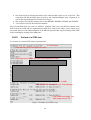
1
Extension of the Test Coverage
of the Automatic Band Switch Feature
in the Low Layers of Mobile Phones
DAVID PAUCHET
Master’s Degree Project
Stockholm, Sweden 2005
TRITA-NA-E05020
Numerisk analys och datalogi
KTH
100 44 Stockholm
Department of Numerical Analysis
and Computer Science
Royal Institute of Technology
SE-100 44 Stockholm, Sweden
Extension of the Test Coverage
of the Automatic Band Switch Feature
in the Low Layers of Mobile Phones
DAVID PAUCHET
TRITA-NA-E05020
Master’s Thesis in Computer Science (20 credits)
at the School of Computer Science and Engineering,
Royal Institute of Technology year 2005
Supervisor at Nada was Karl Meinke
Examiner was Stefan Arnborg
Abstract
GSM is the basic protocol that was used in the first mobile phones. Although some new 3G
protocols are more performing, GSM will remain the heart of mobile telephony history. The first
part of this master thesis will present the development of telephony, of cellular telephony and of
this protocol in particular. General aspects of the GSM specifications will then be described,
gradually specializing in the issues of PLMN selection. Motorola’s automatic bandswitch feature
will then be explained, as well as its improvement, named EAB. The aim of this work being the
testing of this feature, a theoretical description of testing methodology will first been shown,
before the practical reasons concerning the choice of relevant tests are evoked.
Thanks
I would like to thank people at Motorola Toulouse who advised and helped me during this master
thesis, especially in the STEP team and in my team.
I address special thanks to Philippe IVARS, who greeted me at the beginning of the master thesis
and who was then always there to answer my questions. Thanks to Amanda FIORILLO, who
helped me when he was not there. Thanks to Antoine ZOGHBY who first proposed me this
interesting project. In the STEP team, thanks to Audrey SIMON, Briag MONNIER and Marouan
BENABDELLAH CHAOUNI.
Finally, I wanted to thank Karl MEINKE in NADA, who helped me define the boundaries of the
subject, find all the necessary documentation, and make this report most agreeable and interesting
to read.
Table of contents
0
1
Index........................................................................................................................................1
Introduction...........................................................................................................................3
1.1
Historical development of cell phones ..................................................................3
1.2
Cellular phone standards ..........................................................................................3
1.2.1
Prehistory .............................................................................................................4
1.2.2
GSM history .........................................................................................................4
1.2.3
GSM today ............................................................................................................5
2 GSM overview......................................................................................................................6
2.1
GSM architecture.........................................................................................................6
2.1.1
Global architecture.............................................................................................6
2.1.2
The MS...................................................................................................................7
2.1.3
The BSS.................................................................................................................7
2.1.4
The NSS.................................................................................................................8
2.1.5
The OSS ................................................................................................................9
2.2
Itinerancy management: roaming and handover...............................................9
2.2.1
Cells and location areas ...................................................................................9
2.2.2
Local roaming.....................................................................................................10
2.2.3
International roaming .......................................................................................11
2.2.4
Handover..............................................................................................................11
2.3
The logical channels.................................................................................................12
2.3.1
Bursts ...................................................................................................................12
2.3.2
Frame, multiframe, superframe, hyperframe .............................................12
2.3.3
Channels ..............................................................................................................13
3 The process of PLMN selection seen from the low protocol layers....................15
3.1
L1, RR and MM protocol layers..............................................................................15
3.1.1
L1 ...........................................................................................................................15
3.1.2
RR ..........................................................................................................................15
3.1.3
MM .........................................................................................................................15
3.2
When should we choose a new PLMN? ..............................................................15
3.2.1
Power-up..............................................................................................................16
3.2.2
Loss of camp ......................................................................................................16
3.2.3
Network registration failures..........................................................................16
3.2.4
Periodic HPLMN scan.......................................................................................16
3.2.5
Manual network search or new network search .......................................16
3.3
Particular PLMNs.......................................................................................................17
3.3.1
Registered PLMN ...............................................................................................17
3.3.2
Home PLMN ........................................................................................................17
3.3.3
Preferred PLMNs................................................................................................17
3.3.4
Forbidden PLMNs..............................................................................................17
4 The Enhanced AutoBand feature ..................................................................................19
4.1
European and American frequency bands.........................................................19
4.1.1
List of frequency bands...................................................................................19
4.1.2
Regional presence of frequency bands ......................................................19
4.1.3
ARFCN and induced problem ........................................................................20
4.2
Basic Autoband..........................................................................................................21
4.2.1
Automatic band switch ....................................................................................21
4.2.2
When can it be used?.......................................................................................21
4.2.3
Limitations...........................................................................................................21
4.3
Enhanced AutoBand.................................................................................................22
5 Testing a communication protocol...............................................................................23
5.1
Why use formal methods? ......................................................................................23
5.1.1
A history of automated validation.................................................................23
5.1.2
The advantages of formal design..................................................................23
5.2
Formal methods.........................................................................................................24
5.2.1
Design criteria ....................................................................................................24
5.2.2
Formal languages..............................................................................................25
5.2.3
Validation methods ...........................................................................................25
5.3
Finite State Machines methods .............................................................................26
5.3.1
Definitions ...........................................................................................................26
5.3.2
State identification and verification..............................................................26
5.3.3
Conformance testing ........................................................................................29
5.3.4
FSMs in the reality.............................................................................................31
6 Testing the EAB .................................................................................................................32
6.1
Description of the test tool: STEP ........................................................................32
6.2
The main groups of tests ........................................................................................33
6.2.1
Power-up with SIM ............................................................................................33
6.2.2
Power-up without SIM ......................................................................................33
6.2.3
Loss of camp ......................................................................................................33
6.2.4
Network registration failures..........................................................................33
6.2.5
Periodic HPLMN search...................................................................................33
6.2.6
Manual network search....................................................................................33
6.2.7
New network search .........................................................................................34
6.2.8
Cellar Effect.........................................................................................................34
6.3
The varying parameters...........................................................................................34
6.3.1
Automatic vs. manual network selection....................................................34
6.3.2
Autoband vs. chosen band.............................................................................35
6.3.3
Phone capability ................................................................................................35
6.3.4
Last band selected and RPLMN ....................................................................35
6.3.5
Other specific PLMNs.......................................................................................36
6.3.6
The radio environment.....................................................................................36
6.3.7
EAB Algorithm initialization parameters.....................................................36
6.4
Tests procedures.......................................................................................................36
6.4.1
Feature Complexity and test coverage........................................................36
6.4.2
Three scripts, one test .....................................................................................37
6.4.3
Outlook of a STEP test.....................................................................................38
6.5
Tests results ...............................................................................................................39
7 Conclusions and further work .......................................................................................40
References ..................................................................................................................................41
0 Index
This section lists the abbreviations used in this document.
AGCH: Access Grant CHannel
ARFCN: Absolute Radio Frequency Channel Number, number from 0 to 1023 representing a
frequency.
BCCH: Broadcast Control CHannel
BSC: Base Station Controller, subpart of a BSS, controls a set of BTS.
BSS: Base Station Subsystem, part of the GSM architecture used for radio resource management
BTS: Base Transceiver Station, subpart of a BSS, first emitter-receiver linked to the MS.
CBCH: Cell Broadcast CHannel
EAB: Enhanced AutoBand feature, Motorola feature enabling to switch from the European to the
American frequency bands and vice-versa
FACCH: Fast Associated Control CHannel
FCCH: Frequency Correction CHannel
FPLMN: Forbidden PLMN, a PLMN on which the MS is only allowed to camp on emergency
FSM: Finite State Machine, set of states linked by transitions, used to formalize a behavior
HLR: Home Location Register, subpart of a NSS, global database on users
HPLMN: Home PLMN, PLMN to which the user has subscribed
IMEI/IMSI: International Mobile Equipment/Subscriber Identity, to find a phone/subscriber in a network
KTH: Kungliga Tekniska Högskolan, great university
L1: Layer 1, physical layer in the MS architecture
LA: Location Area, group of adjacent cells
LAC: Location Area Code
LAI: Location Area Identifier, corresponds to the PLMN number (MCC and MNC) and the LAC
LRPLMN: Last Registered PLMN, see RPLMN
LU: Location Update, update of the location area of a MS
MCC: Mobile Country Code
MM: Mobility Management, one of the MS low protocol layers
MMI: Man Machine Interface
MNC: Mobile Network Code
MS: Mobile Station, a mobile phone with a SIM card
MSC: Mobile services Switching Center, subpart of a NSS, commutator.
MSISDN: Mobile Station ISDN number, the international phone number, known to the user
NSS: Network SubSystem, part of the GSM architecture used for call establishment and mobility
OSS: Operation SubSystem, part of the GSM architecture used by the operator to administrate
the network
PCH: Paging CHannel
PLMN: Public Land Mobile Network, a network to which a user can subscribe to send and
receive calls
PPLMN: Preferred PLMN, highest-priority PLMN after the HPLMN and RPLMN
RACH: Random Access CHannel
RPLMN: Registered PLMN, PLMN on which the MS is currently camped
RR: Radio Resource Management, one of the MS low protocol layers
1
SACCH: Slow Associated Control CHannel
SDCCH: Stand alone Dedicated Control CHannel
SCH: Synchronization CHannel
STEP: Simulator Tool for Early Protocol, simulator developed by Motorola to do tests on the
low-protocol layers
TMSI: Temporary Mobile Station Identity, temporary number used to hide the IMSI
UIO: Unique Input-Output, a UIO sequence verifies a FSM is in a given state
VLR: Visitor Location Register, subpart of a NSS, local database often linked to a MSC
2
1 Introduction
1.1 Historical development of cell phones
“Mr. Watson -- come here -- I want to see you.”
Such were the first words Alexander Graham Bell uttered to his assistant in 1876, in a device that
could transmit messages electrically – called the telephone.
The patent for this revolutionary device was put down in 1870, by Elisha Gray, and Alexander
Graham Bell, within hours. It was finally Graham Bell who was officially recognized as the
creator of the phone, and who managed to perform such an incredible communication for the first
time in 1876. This inventor wanted to create an evolution of the telegraph, by conjecturing that
several messages could be transmitted at the same time on the same wire.
The telephone has gone through a very long way since 130 years, changing its look, ameliorating
its performance, evolving along with society.
The beginning of wireless telephony occurred in the early 50’s, when emitter-receiver devises
were designed, using the 27 MHz band. These phones were influenced by the military TalkyWalky system, and could emit as far as 30 km. They used a lot of energy and were often installed
in cars. Researchers discovered that it was possible to increase substantially the traffic capacity
by using many small cells that would emit to some cellular phones. However, the required
technology was not available yet.
At the beginning of the 70’s, this system evolved in an automatic system, that became available
to more (but still not many) people, but only in big cities.
In 1977, AT&T Bell produced the first cellular system prototype, which was tried for the first
time one year later in Chicago. The first commercial cellular telephone was Japanese, in 1979.
After Motorola and American Radio had achieved a second series of tests with another prototype
in 1981, commercial cellular service was finally allowed in the USA.
During the 80’s, most of today’s big telecommunication companies developed and the
telecommunication lobby structured.
So far, the first-generation mobiles were analogical. In 1991, GSM, which will be studied further,
was designed and launched the second-generation wave of mobiles.
Today, third-generation cell phones are developed.
3
1.2 Cellular phone standards
1.2.1
Prehistory
A long, long time ago, in the 80’s, was no global protocol to be found. Thy mobile phone could
only emit to limited areas, and thee could certainly not communicate worldwide!
The Americans devised the AMPS protocol, which was tried in 1979 and commercialized in
1983. Thus the American people was able to communicate throughout the United States, although
that was merely not possible between them and their Canadian neighbors, who invented
AURORA-400 at the same time.
The Europeans, proud to be much less able to communicate between them than on the NorthAmerican mainland, designed various other protocols. It began well with Nordic Mobile Phone –
NMT450 – that was used between Nordic and Benelux countries, and could have been an embryo
of a unified European protocol. Alas, Great-Britain produced TACS (Total Access
Communications System) four years later, soon followed by Germany with their C-NETZ, France
with their Radiocom 2000, and Italy with their RTMI/RTMS. Eventually, Europeans had to cope
with nine different, incompatible radio telephone systems.
Phone sales were naturally more significant in the USA than in Europe. Fortunately, the system
that would enable Europeans to escape the consequences of this remake of the Babel tower
scenario was developed step by step during the same years…
1.2.2
GSM history
The first essential condition to have a telephony service all over Europe is to define the same
frequency band that will be used by everybody on the territory. That was done as soon as 1979,
with the World Administrative Radio Conference, that opened the 900MHz band for mobile
phones use.
In 1982, the European Conference of Posts and Telecommunications allocated the band from 890
to 915 MHz for the communications from the terminal to the network, and the band from 195 to
930 MHz for communications the other way. Simultaneously, the Groupe Spécial Mobile (GSM)
was created, to specify a European communication protocol for 1990.
In 1985, after the project had developed slowly, the EEC decided to make the protocol designed
by the GSM a protocol used by all member countries. In this group, France and Germany
especially worked together.
In 1987, the phone operators in thirteen European countries signed an agreement to open
simultaneously the GSM protocol in 1991. This agreement is called the Memorandum of
Understanding (MOU).
4
But the technical specifications were only finished in March 1990. From there on, there was a
considerable amount of work to perform, in hardware as well as software. The aim of the
operators rapidly became to limit the lateness as much as possible…
In July 1991, the first communication between a mobile phone and a terminal was managed. In
spite of many technical snags, the first networks opened by the end of 1991. Mobile phones broke
through only a few years later.
As GSM networks opened throughout Europe, GSM lost its former French meaning to become
“Global System for Mobile communications”.
Still in 1991, because of a British will, the GSM specifications were adapted to enable the
development of systems in the 1800 MHz band. It is often called DCS 1800.
1.2.3
GSM today
ETSI stands for European Telecommunications Standards Institute. It is an independent company
based in Sophia-Antipolis, near to Nice. In 1995, 350 members worked there. It includes people
representing operators, industrials, administrations, researchers, and users, and they have the
responsibility of the development and evolution of European standards.
GSM has now become the only numeric standard accepted in Europe, and is used in many
countries. However, it is competing with other numeric standards, mainly in the USA and in
Japan.
Today, the MOU had 210 members, spread over 105 different countries. Its aims are to promote
GSM/DCS and to exchange information between the different protagonists involved in mobile
communications.
In August 1998, there were more than 280 operational networks in the world and more than 100
million subscribers.
Last of all, GSM services are now available as well on bands 1900 MHz (PCS 1900) and 850
MHz (GSM 850).
5
2 GSM overview
2.1 GSM architecture
2.1.1
Global architecture
A telephony network consists in four subsets of equipments:
* The Mobile Station (MS), which is the phone possessed by the user.
* The Base Station Subsystem (BSS), which manages radioelectric transmissions and radio
resources. The handover, which is the possibility to move when calling someone, depends
on the BSS.
* The Network SubSystem (NSS), which has all the functions needed for call establishment
and mobility. It is sometimes also called SMSS, which stands for Switching and
Management SubSystem. The itinerancy, which is the possibility to call anywhere – if
there is coverage! – is linked to the NSS.
* The Operation SubSystem (OSS), which allows the operator to administrate its network.
Figure 1: GSM architecture
BSS
MS
NSS
HLR
BTS
VLR
BTS
BSC
MSC
BTS
OSS
BTS
BSC
VLR
BTS
MSC
BTS
6
2.1.2
The MS
A mobile station designates a phone equipped with a SIM card, a device which allows having
telecommunication services from a PLMN (Private Land Mobile Network, for example Orange).
There is a huge variety of phones, having always more functionalities, more battery autonomy
and less volume and weight.
Each MS has a unique identity number called IMEI (International Mobile Equipment Identity)
that also indicates the builder of the phone.
The maximal power for a MS is usually a few Watts.
2.1.3
The BSS
The BSS includes:
* Base Transceiver Stations (BTS), which are minimal emitting-receiving entities,
* Base Station Controllers (BSC), which control a set of BTS and have some higher
functionalities.
2.1.3.1 The BTS
A BTS manages the radio transmission: modulation, demodulation, equalization, error correction
coding. It looks at all the physical layer, and performs all the necessary measures to check a
communication occurs normally. However, it releases the exploitation of these measures to the
BSC.
A rural BTS can manage more than a hundred simultaneous communications, which is a limit
seldom reached. A urban BTS can have more or less twenty simultaneous communications, but
mini-BTSs are much more numerous in the cities or on the motorways.
A BTS covers from one to several square kilometers. Several BTSs are linked to a BSC, in chain
or in star configuration.
2.1.3.2 The BSC
It is the intelligent part of the BSS. It allocates channels, uses the BTS measures to control the
emission power of the MS and of the BTS, and performs handovers, which correspond to the
possibility to move when talking on the phone.
It is also a commutator towards the MSC, which means it will relay information that has to be
transferred to this more central element.
7
There are generally two ways of building BSCs:
* Numerous low-capacity BSCs for rural areas
* High-capacity BSCs for urban areas, where the BSC needs to coordinate many small
BTSs.
2.1.4
The NSS
The NSS includes three kinds of components:
• The Mobile services Switching Center (MSC), which are mobile commutators usually
associated with VLR databases
• The Visitor Location Register (VLR), which is a local database
• The Home Location Register (HLR), which is a user localization and characterization
database.
2.1.4.1 The HLR
The HLR is a database that manages the subscribers of a given PLMN. For each subscriber, it
also memorizes data that changes little with time:
• The International Mobile Subscriber Identity (IMSI), inside the network
• The Mobile Station ISDN number (MSISDN), which is the international phone number,
known to the user
• The subscription profile.
The HLR memorizes the localization of the user (the user’s VLR, see infra), and this is updated
through information transmitted on the network.
The HLR can be designed in a centralized or decentralized way. In the first case, it is a specific
machine containing hundreds of thousands of subscribers. In the second case, it can be integrated
directly in the MSCs, where the data of a given user is stored in the MSC on which the user
communicates most. The only important rule is that each user is assigned a unique HLR.
2.1.4.2 The VLR
A VLR memorizes the same data as a HLR, but only for subscribers inside a specific zone. It also
stores the TMSI (Temporary Mobile Station Identity), which is a temporary number whose aim is
to hide the IMSI.
8
2.1.4.3
The MSC
The MSC is a kind of nervous center for mobile communications. It manages the call
establishment between the phone and another MSC, the transmission of short messages, and the
handover in case the user is moving through different areas when calling.
The MSC communicates with its VLR to get all necessary information on its users.
A MSC can become a Gateway MSC, which is activated at the beginning of a call from a nonmobile to a mobile phone.
In the theory, MSCs and VLRs should be physically separated. Practically, the VLR is often
integrated in the MSC, for matters of convenience.
2.1.5
The OSS
The OSS contains many parts: for example the Telecommunications Management Network
(TMN), the Equipment Identity Register (EIR), and the AUthentication Center (AUC).
Its main roles are:
• Commercial administration (declaration of the subscribers, terminals, bills, statistics)
• Security management (intrusion detection, rights)
• Exploitation and performance management (traffic and quality observation, configuration
changes to adapt to the network load, surveillance of mobiles)
• Control of the system configuration (software update, introduction of new equipments and
functionalities)
• Maintenance (flaws detection, equipment tests).
2.2 Itinerancy management: roaming and handover
2.2.1
Cells and location areas
A cell is the area where a BTS has coverage. In a cell, it is possible for a MS to make calls by
communicating with this BTS.
To be able to move from cell to cell, a simple method was used in the past: when you went out of
the current cell, the network simply asked all cells where the phone was last seen. But this is quite
wasteful, and can only be used for small populations.
A better idea is to introduce the concept of location areas (LA). A LA groups some adjacent cells
together (from a few to 20 or 30). When the network needs to know where a user is when he/she
has gone out of a cell, the system looks in the current LA, which will emit some paging messages
to find the phone.
9
To use this method, the network must keep in mind the address of the current location area of the
MS. A LA is identified by three numbers: MCC, which indicates the country of the PLMN;
MNC, which indicates the number of the PLMN inside the country; and the LAC, which is the
number of the LA. These 3 numbers constitute a LAI (LA Identifier).
Once the LA is found, a cell is defined by its frequency, represented by the ARFCN number. It
also has a color code, to differentiate it from possible cells that could both be near and have the
same frequency.
2.2.2
Local roaming
Local roaming corresponds to the situation when the user is moving from one location area to
another. A location update is needed. This can only happen when the mobile is in idle mode, i.e.
it is not performing a call (this would be dedicated mode).
Within GSM, there exists such a location update (LU) procedure. The decision to perform it
comes from the mobile, which searches the current LAC and compares it to the stored value. It
happens every 6Nth minute, N being an integer.
Globally, there are two kinds of scenarios: whether the LU occurs inside the same VLR or not.
There is a common process before, though.
2.2.2.1 Common process to all scenarios
The MS is in idle mode. It detects some information indicating a new LA. To start the LU, the
phone requests a dedicated channel from the network, i.e. a channel that is not used by any other
user. Then, the MS establishes some connections in order to be able to communicate with the
MSC managing the cell where the MS is located.
2.2.2.2 Intra-VLR location update
This is the easiest case. The LU information must only be modified in the VLR. The network can
authenticate the mobile, allocate a new TMSI or keep the same.
Typically, this takes 300 ms.
2.2.2.3 Inter-VLR location update
Let us the call VLR1 the origin VLR, and VLR2 the destination VLR.
VLR2 does not know the TMSI of the phone. Hence, the mobile indicates also the whole LAI of
its former LA. Then VLR2 is able to communicate with VLR1. VLR2 copies all the information
10
concerning the user, from the HLR whose address has been given by VLR1. VLR2 does not copy
immediately from VLR1 to avoid error transmission. Once this is done, VLR1 erases its
information on the user. A new TMSI is reallocated.
The IMSI may be used instead of the TMSI, in some special circumstances like on power-up,
when a TMSI has not yet been allocated.
This procedure is slower and takes 5s.
2.2.3
International roaming
Each subscriber has a Home PLMN (HPLMN). But when he/she leaves the HPLMN coverage
and is under coverage of another Visited PLMN (VPLMN), the MS may camp on the VPLMN (if
some agreement with the HPLMN exists), and this is called international roaming.
The location update follows roughly the same outlines as for the previous exceptions. However,
the MSC in VPLMN cannot communicate directly with the subscriber’s VLR. It must make use
of the HPLMN network, the VPLMN network, and the international network.
The protocol messages aspects and the different possible situations will be developed later, since
this corresponds to the main theme of this master thesis.
2.2.4
Handover
A handover corresponds to the allocation of another dedicated channel to the MS when it is
already in dedicated mode, i.e. when it is having a call.
There are two kinds of very different handovers: intra-cellular or inter-cellular.
2.2.4.1 Intra-cell handover
When the quality of the received signal becomes poor, at the same time the emitted power in the
cell is high, it means that the problem may come from interferences in the current channel. Intracell handover then corresponds to the commutation of the call to another channel inside the same
cell.
2.2.4.2 Inter-cell handover
An inter-cell handover happens when the signal quality would become better in a new cell.
Typically, it can happen when you are calling someone in the street, and you continue walking
until the power of the cell where the call was originated becomes too low.
11
An other possible cause of inter-cell handover is when there is too much traffic on a cell, the call
is then redirected towards a neighboring cell less used.
2.2.4.3 Main phases in a handover
During a handover, the following operations are performed:
• Suspension of all normal operations except the radio resources (RR) management layer,
• Disconnection of the signalization link, and possibly of the traffic channel,
• Disconnection, deactivation and freeing of formerly allocated channels,
• Activation of new channels and connection if necessary,
• Establishment of a data link connection on the new channels.
2.3 The logical channels
2.3.1
Bursts
A burst is the basic element of data transmission in GSM. It has a length of 156.25 bits, which are
successively sent. There are four kinds of non-dummy bursts:
• The normal burst (N), which is used to carry data and most signaling,
• The frequency burst (F), whose aim is to be synchronized in frequency with the cell
signal,
• The synchronization burst (S), whose aim is to be synchronized in time with the cell
signal,
• The access burst (A), which is a shorter version of the normal burst and is used to request
channel allocation.
A burst is also called a time slot, and lasts 0.577 ms.
2.3.2
Frame, multiframe, superframe, hyperframe
From the time slots, several layers of information structures are built:
* A frame corresponds to 8 time slots, and lasts 4.615 ms,
* A multiframe is either a set of 26 frames (120 ms), or a set of 51 frames (235.4 ms),
* A superframe is either 51 26-multiframes or 26 51-multiframes. It lasts 6.12 s,
* A hyperframe corresponds to 2048 successive superframes, for a total time of 3h 28mn
53s 760ms.
12
2.3.3
Channels
These structures enable us to transmit information. But it would be wasteful to use a whole
multiframe, for example, only for one kind of information. So, we need to define different types
of logical channels. A logical channel is assigned a specified set of slots on a multiframe, and will
read its information there. Then each slot of a multiframe will have a specific function.
There exist two groups of logical channels: signaling channels and traffic channels. At a given
time, different associations of these channels are possible, depending on the needs.
2.3.3.1 Signaling channels
•
Frequency Correction CHannel (FCCH): synchronizes frequency with a base station to be
able to communicate with it.
•
Synchronization CHannel (SCH): synchronizes time with a base station to be able to
communicate with it; it is used at the same time as FCCH.
•
Broadcast Control CHannel (BCCH): broadcasts regularly information in each cell, to be
listened to by all the mobile stations in idle mode. It exists only in downlink transmission.
•
Paging CHannel (PCH): it is used by the network to page the MS, the network broadcasts
information in order to perform a call, send a SMS or authenticate.
•
Access Grant CHannel (AGCH): it is used by the network to inform an idle MS it has to
switch to a dedicated channel.
•
Random Access CHannel (RACH): allows any MS to transmit its access request to the
network. The MS may do so at a random time.
•
Cell Broadcast CHannel (CBCH): in the cells where it is implemented, allows
transmitting short messages from the network to all MSs in idle mode.
•
Slow Associated Control CHannel (SACCH): transports signaling data in parallel with the
transmission of a user data flow. It is associated to a traffic channel.
•
Fast Associated Control CHannel (FACCH): as SACCH may be too slow, it may be
preferable to use FACCH, which will avoid delay. But it is not transmitted periodically as
SACCH.
•
Stand alone Dedicated Control CHannel (SDCCH): dedicated channel that allows
transmitting control data at a high rate.
13
2.3.3.2 Traffic channels
Traffic CHannels (TCH) are dedicated channels used to transmit coded speech and data. There
are several kinds of TCHs, depending on the desired rate and on whether speech (at full- or halfrate) or data is transmitted.
14
3 The process of PLMN selection seen from the low protocol
layers
3.1 L1, RR and MM protocol layers
L1, RR and MM are the names of the protocols layers on which my master thesis takes place.
They are low protocol layers, which are described in the following paragraphs, from lowest to
highest.
3.1.1
L1
L1 stands for Layer 1. It is the physical layer, which communicates directly with the
receiving/emitting part of the system.
3.1.2
RR
RR is the Radio Resource management layer. Its main role is to establish a dedicated channel, or
to reestablish it after a handover.
3.1.3
MM
MM, or Mobility Management, is a layer whose main roles are:
• To manage mobility, that is update the location through communication between the MS
and the network,
• Insure security functions,
• Manage MM connections, which are a way to connect directly without mobility issues.
The main function that will be developed further is the first one, since it contains all the problems
of PLMN selection and reselection.
3.2 When should we choose a new PLMN?
This Master Thesis handles a specific aspect (described in 4.) of all problems linked to PLMN
selection and reselection. We will now describe all the situations when this event may happen.
15
3.2.1
Power-up
When the phone is switched on, it needs to register as soon as possible on a new PLMN. But it
will be possible to send calls only if a SIM card is inserted (and if an available PLMN is found, of
course!). If the last PLMN on which the MS was registered is found, the MS will register on this
one.
3.2.2
Loss of camp
We may lose the connection to the current PLMN in several situations: for example, you are in a
car and you drive into a tunnel; or you simply walk out of the coverage area of your provider.
In this situation, the phone will try first to recamp (i.e. reconnect) on the same PLMN. If it is not
possible, it will try to connect on other PLMNs.
3.2.3
Network registration failures
If the phone cannot update its location four times in a row, communicating would be useless, and
a special procedure is engaged as a consequence. The MS tries to camp on a new available
PLMN.
3.2.4
Periodic HPLMN scan
Every 6Nth minute, where N is an integer, the phone performs a home PLMN search if it is not
already camped on its home PLMN – i.e. the PLMN for which the user has subscribed. If the
home PLMN is found, the MS leaves the last PLMN to camp on this one.
3.2.5
Manual network search or new network search
At any time, the user may request a manual network search. The result is a PLMN list appearing
on the screen, and the user will have to choose the PLMN that he wants to use.
Motorola has also developed the “New Network” option, which tells the phone to camp on a
PLMN other than the PLMN being currently camped on.
16
3.3 Particular PLMNs
For the following sections, it is important to distinguish between the different possible attributes
of a PLMN, and to remember the abbreviations used. Here is a list presenting the different
specific PLMNs that will be used.
3.3.1
Registered PLMN
The Registered PLMN, or RPLMN, is the PLMN on which the MS is currently camped. When
searching a PLMN (for example if the phone loses track of the RPLMN), the RPLMN will nearly
always have highest priority.
Another abbreviation that can be used is LRPLMN, which stands for Last Registered PLMN. It
intervenes for example at power-up, when the phone remembers it was last camped on this
PLMN.
3.3.2
Home PLMN
The Home PLMN, or HPLMN, is the PLMN for which the user has subscribed. If the phone is
allowed to camp on PLMNs other than the HPLMN, it is because the HPLMN has made
commercial agreements with those other PLMNs.
When the RPLMN cannot be found, the HPLMN is chosen. The exception is for the periodic
HPLMN search, when the HPLMN has a higher priority than the RPLMN.
3.3.3
Preferred PLMNs
A MS may have a list of Preferred PLMNs, or PPLMNs. A PPLMN will be chosen first if neither
the (L)RPLMN nor the HPLMN can be found.
If several PPLMNs are mentioned, they are sorted by order of decreasing preference.
3.3.4
Forbidden PLMNs
A Forbidden PLMN, or FPLMN, is a PLMN on which it is forbidden to camp for the phone.
At power-up, the FPLMN list is empty, and is filled up after each failed attempt to camp on a
PLMN. Assume a given user has subscribed for Orange. At power-up, SFR and Orange cells are
found. The phone tries to camp on a SFR cell, but is rejected. As a consequence, SFR is added to
the list of FPLMNs (until next power-down).
17
If no suitable PLMN is found at a given time, and if only FPLMNs are available, then the phone
will not camp normally, but will camp on emergency instead. That means the MS will camp on a
FPLMN cell, but will only be able to launch emergency calls. In this state, the MS will only
receive information from the network and will not be able to perform any call. However, calling
emergency numbers such as the police or the fire brigade remains possible.
18
4 The Enhanced AutoBand feature
This is the feature for which tests had to be designed during my Master Thesis. The feature will
be abbreviated as EAB.
4.1 European and American frequency bands
4.1.1
List of frequency bands
Basically, GSM was only designed to be used in the 900 MHz frequencies (GSM900), which
were made available by some European governments. The United Kingdom rather used the 1800
MHz frequencies, which were then added to the GSM capability (DCS1800). Some enlargements
of the band width of GSM 900 were performed, distinguishing EGSM (Extended GSM) from
PGSM (Primary GSM). In the following, the combination of both will be referred to as GSM900.
900 and 1800 are the European frequency bands. Before the introduction and the treatment of the
American bands, the most performing phones in terms of frequency coverage were thus dualband phones, with coverage 900/1800.
But the USA had decided to use other frequency bands, surrounding 1900 and 850 MHz. So,
GSM had to adapt, and PCS1900 appeared, soon followed by GSM850. From there on, Motorola
has tried to offer new services, with tri- or quad-band, covering European and American bands.
But adding the 850 and/or 1900 capability to phones is much less easy than adding 1800 to 900,
for example because there can be frequency overlapping between some bands.
4.1.2
Regional presence of frequency bands
The following map shows the geographic repartition of the frequency bands used by the operators
in the different countries of the world.
We can divide the world into two large regions: America and the rest.
In Europe, Asia, Africa, Australia, and in the Pacific, the European bands 900 and 1800 are used.
However there are a few exceptions, in which:
• Thailand, which also has a 1900 network (and 3G, though it is not indicated on the map)
• Japan and South Korea, where the coverage is only 3G.
19
Figure 2: Frequency bands used in the world
It is remarkable that Europe is the most homogenous region, where all countries except Belarus
(only 900), have a coverage on both 900 and 1800.
The largest variety of frequency bands appears in America. Both American bands, i.e. 850/1900,
can be found in the USA, in Canada and in Paraguay. Other countries only have coverage on 850,
like Colombia, or on 1900, like Mexico.
But some American countries have European bands instead, like Cuba (probably as a desired
contrast to the USA!). Argentina is the only American country to have some coverage on both
European and American bands, i.e. on 900 and 850/1900.
No country in the world has coverage only on the 1800 band (though Brazil is not far from it).
The main conclusion of this map is that it is unavoidable to develop telephones that can switch from
the European to the American bands, and vice-versa, and particularly for countries like Thailand
or Argentina.
4.1.3
ARFCN and induced problem
An international agreement created the ARFCN, which stands for Absolute Radio Frequency
Channel Number.
Each cell has an ARFCN number, which represents a given frequency. It is ranged between 0 and
1023.
20
With dual-band phones on 900/1800, it was guaranteed this number corresponded to a unique
frequency. Unfortunately, it became more complex with the introduction of the 850 and 1900
bands. As a matter of fact, there is a large overlapping between DCS1800 and PCS1900:
• ARFCN for DCS1800 range from 512 to 885,
• ARFCN for PCS1900 range from 512 to 810.
This issue contributes to the complexity of the automatic band switch feature, which offers a way
to handle the problem.
4.2 Basic Autoband
4.2.1
Automatic band switch
Automatic band switch, autoband in short, is a feature that permits to perform calls with the same
MS, in countries where the coverage is 900/1800 or in countries where the coverage is 850/1900.
At power-up, the MS scans the usual frequency band to find its RPLMN or HPLMN. If it finds
no coverage, it treats the possibility that we are in another country, supporting other frequency
bands.
The MS then searches on the other possible frequencies.
4.2.2
When can it be used?
This feature is useful for people living near to the border of two differently covered countries,
like between Chili and Brazil. It can also be used when people travel from Europe to the USA for
example, and avoids buying another phone that would cover the other frequency bands.
4.2.3
Limitations
Since the time of the original design of the Autoband feature, there is now at least one country
that has coverage on both European and American frequencies.
Today, Thailand is an example of such a country. While in Bangkok, TOT provides a 1900
coverage, the rest of the country has a 900/1800 coverage with AIS. As a consequence, someone
that powered on his/her phone in the capital city will not be able to call anybody once he/she has
left the town! In the same way, a person coming from the countryside with the MS switched on
will have no coverage in Bangkok!
21
This is not the only limitation. The same problem occurs for the previously mentioned people at
the border of Chili and Brazil. If they want to eat a taco on the other side of the border, their
phones will not be able to recognize the frequency bands, unless they switch off their phone, and
switch it on again.
4.3 Enhanced AutoBand
Enhanced AutoBand, EAB in short, is an improvement of the previously described feature whose
aim is to palliate its limitations.
With the EAB, it is possible to look on both European and American bands, not only at
power-up, but anytime when a PLMN reselection process intervenes. The consequence is the
possibility to travel anywhere without ever switching the phone off!
However, a user may wish to stay only on European bands or on American bands. The reason
may be quickness matters, or energy saving. To do this, a network option on the phone allows the
user to choose between Autoband, 900/1800 or 850/1900.
The EAB algorithm involves several software components of the phone from low layers of GSM
protocol to MMI. It introduces several new concepts, algorithms and variables that have to be
thoroughly analyzed before attempting to test them.
22
5 Testing a communication protocol
Communication protocols, such as GSM, are very complex. One way or another, we have to
perform tests to avoid the inevitable bugs that would occur if we did nothing. This section
presents the use of formal methods to do tests. In a first part, the interest of formalization is
shown. The basics of formal testing are then presented, before an example of a formal method –
Finite State Machines (FSMs) – is developed in the last part.
5.1 Why use formal methods?
5.1.1
A history of automated validation
The first automated validation attempt goes back to 1970. At this time, the perturbation (or
reachability) concept was introduced. It consists, for a given state of the system, in deriving all
the possible successor states, and continuing recursively until all states have been reached. The
involved researchers then discovered that it was possible to reveal design errors even in simple
protocols, that would have been very difficult to detect had the analysis been made manually.
However, they had no high-level notation in 1970 and the verification was tricky.
In 1980, automatic proofs still required a great deal of work. For each new specification problem,
most of the verification code had to be rewritten. The automatic validation was still far from
being a method accessible to the engineer.
Later, special-purpose languages were a breakthrough. They could be used to specify the
validation system’s input. The consequence was the possibility to directly use the perturbation
analysis from the output of a parser run on a formal specification. But there were still major
limitations, such as the difficulty to analyze the origin of inconsistencies.
Today, it is possible to map machine states to specifications states much more efficiently. Highlevel specification languages are at our disposal, such as Promela. There is near certainty that the
regular use of such a language could make us detect errors in the protocols specifications of the
last ten years! However, the use of formal testing is still not widely known, although it is ready to
bring much to the industrial companies that could need it.
5.1.2
The advantages of formal design
In a traditional design cycle, we can distinguish three main steps:
1 – High-level design, when the global design is thought according to the requirements
2 – Low-level design, when designers further detail the solution found in step 1
3 – Coding and testing, when the code is divided between the programmers to be
implemented
23
Today, in industrial companies, and especially in Motorola, most of the time is spent on the
third phase. Since there is no formal verification for high- and low-level design, coding is the first
step in the process when the engineers have to face a formal, unambiguous language, which is
here the programming language.
The consequence of this is that too much time is spent on debugging the implemented code, a
problem that could have been avoided if we had used a formal method to check the validity of the
design during a previous step. Furthermore, when debugging in step 3, we often have to go back
to the low-layer design, or even sometimes to the high-level design, which is a pure waste of
energy.
Hence, the solution is to use formal verification softwares, with whom it will be possible to
formally validate the design levels, and be assured that the debugging phase will be minimal
since it will not be based on an inconsistent design.
5.2 Formal methods
5.2.1
Design criteria
A formal method needs to use:
• Unambiguous notations
• An effective validation tool that will check the logical consistency of high-level
specifications.
Three kinds of criteria have to be used to check the correctness of a protocol:
• General logical correctness criteria, they do not depend on the type of protocol that is
being tested. This category groups all common errors such as deadlocks, unspecified
receptions, or buffer overflow.
• Protocol-specific correctness criteria. For GSM, such a criterion could be: “MM must
receive a REG_REQ primitive at power-up”.
• Real-time performance requirements. This can correspond to a limited time for call
establishment, for example.
The first two types of criteria aim at avoiding underspecification – we reach a state where we do
not know what to do – or overspecification – some code is never reached. The third criterion
necessitates a methodology different from the other two, and it will not be detailed further.
24
5.2.2
Formal languages
5.2.2.1 Single and dual languages
Two aspects have to be tested: the specifications, and the requirements, that correspond to the
first two types of design criteria. Depending on what we are looking for, we can use a single
language or a dual language.
If we use a single language, only the specifications are translated, and the requirements are not.
The aim is to transform step by step a simple high-level design into a more detailed design by
proving the successive equivalences.
If we use a dual language, we have different formal notations for the specifications and for the
requirements. The proof method is independent from the protocol, and more effective.
We will now look in further detail into the dual language choice, which is the most realistic one
if we want to be able to adapt quickly to any kind of problem.
5.2.2.2 Behavior and specifications requirements
Different languages have to be used for the specifications and for the requirements, because they
do not express the same things. Whereas the specifications describe how the system works, the
requirements tell what result we await from the system.
There are many ways to formalize the specifications. Among the most used, we can quote the
extended finite state machines (see 5.3) and full-fledged programming languages.
On the other hand, the requirements are very often formalized using temporal logic. However,
one given formalization cannot cover all the cases, and we need to choose the best subset of
criteria for which it will be possible to perform a formal verification.
5.2.3
Validation methods
Validation is the step when the previous formalizations are used, to check the requirements are
fulfilled in the given specification.
As the specifications grow more complex, we have to face a problem of states explosion. To
compensate for this, we can try to have more powerful machines (that’s already the case!) and
techniques. Here are three examples of improvements that have been brought to validation
algorithms.
25
5.2.3.1 On-the-fly verification
Earlier, multi-pass algorithms were used. But all states needed to be created before the
verification could really begin. This is near to impossible in some problems where only samples
of the states set can be studied simultaneously. On-the-fly-verification ameliorates this, because
the states are not all created before. Breadth-first or depth-first methods can be used, but the latter
one is the best one.
5.2.3.2 State-space compaction
This method is faster than the previous one, but there is a low probability that some states will not
be covered. However, the better efficiency of state-space compaction allows it to be used for
industrial problems. In this method, we use a hash function for the different states. The hash table
has a limited size, and finding a state that has an already used hash value stops the search of the
branches coming from this state. The state coverage depends on the ratio of the memory used for
the hash table over the memory used for the states.
5.2.3.3 Partial-order semantics
They reduce the number of interleavings (i.e. the choices of action in a given state) that have to
be explored. As a matter of fact, it is usually very difficult to find if two interleavings lead to the
same result. Partial-order semantics allow the unordering of independent events of concurrent
processes. Completeness remains, and the required computation drops by 60 to 80 percent.
5.3 Finite State Machines methods
The theory of Finite State Machines (FSMs) is a vast theory, which revives today with the
problem of testing communication protocols. Their study brings methods that can substitute
brute-force methods when trying to prove formally something on a huge amount of states.
5.3.1
Definitions
5.3.1.1 Finite State Machines
A Finite State Machine is a set of states linked by transitions governed by a transition function,
with an input and an output. There are two kinds of FSMs: Mealy and Moore machines. The only
difference is that for a Moore machine, each time a different output is given, the other parameters
being identical, we have another state, whereas in the Mealy Machine, the output is given in
transitions from one state to the other. Then, a Moore machine is clearer but a Mealy machine has
26
much fewer states. Because we know we have to face a state explosion, Mealy machines will be
used.
A Mealy machine M is a quintuple (I, O, S, δ, λ), where I, O and S are finite, non-empty sets of
input symbols, output symbols and states, respectively.
δ: SxI Æ S is the transition function,
λ: SxI Æ O is the output function.
A transition between two states is usually represented as an arrow, with the comment input/output
near to it. It links two states, represented as circles.
The meaning of δ and λ is extended, so that the input can be a list of input variables, taken one
after the other, and so that the output is the concatenation of the successive outputs when we go
through the FSM.
Two states S and S’ are said to be equivalent if and only if, for a machine of N states:
∀ x input sequence, λ(S,x)= λ(S’,x)
a/0
1
3
a/0
a/1
b/1
a/0
5
b/0
4
b/0
b/0
a/0
b/1
2
¾ Here, states 1 and 2 are equivalent. If the input begins with a b, both states will output 1
and lead to state 4. If the input begins with a a, both states will output 0 and lead to states
3 or 5. So 1 and 2 will be equivalent if and only if 3 and 5 are equivalent. For states 3 and
5, an input a will give output 0 and lead to state 3; an input b will give output 1 and lead
to state 4. So 3 and 5 are equivalent, and thus, so are 1 and 2.
Two machines M and M’ are equivalent if and only if:
∀ S state of M, ∃ S’ state of M’ so that S and S’ are equivalent.
a/0
6
7
a/0
a/1
b/1
b/0
8
b/0
27
¾ Quite simply, it was possible to create a machine that is equivalent to the previously
drawn machine. State 6 is equivalent to states 1 and 2; state 7 is equivalent to states 3 and
5; state 8 is equivalent to 4.
Let M=(I, O, S, δ, λ) and M’=(I, O, S’, δ’, λ’) be two FSMs with the same input and output. We
say φ is a homeomorphism (or morphism) from M to M’ if and only if:
∀ s∈S, ∀ a∈I, δ’(φ(s),a)= φ(δ(s,a)) and λ’(φ(s),a)= λ (s,a)
If φ is a bijection, then it is called an isomorphism, and M and M’ are isomorphic. Two
isomorphic machines are also equivalent, but it is not reciprocal.
¾ Counter-example: we saw that the two machines described upper are equivalent. But they
are not isomorphic: it it were the case, the isomorphism being also a bijection, the number
of states in both machines would be the same.
From each machine, we can construct an equivalent minimized machine, which will have the
minimal possible number of states. To do this, we group states that have the same behavior (same
inputs, same outputs…).
5.3.1.2 Testing a FSM
We now have a finite state machine that represents what we want to test. So, what and how are
we going to test it?
Usually, concerning a machine M, four fundamental questions are raised:
1 What will the final state be after we have run a given test?
2 What is the initial state of the machine, and how to verify it?
3 If we are given a specification, is M equivalent to the specification machine?
4 What does machine M do?
The first two problems are more generic. Between the last two, the third question corresponds
most to the aim of the tests I have done at Motorola. So it will be developed more, and the last
point will be neglected.
To get answers to these questions, we need to perform tests. A test may be preset or adaptive.
A preset test is a test where the input sequence is fixed at the beginning and does not change.
An adaptive test is a test where the input changes according to the previously observed outputs. It
has a tree structure.
For the tests, what is used is only a list of messages that have to be checked or sent, which corresponds to
preset tests. So, adaptive tests will not be developed further.
5.3.1.3 Particular sequences
For a reduced machine, a homing sequence is a sequence of inputs, for which, whatever the
starting state, we know in which state the machine is after the input is applied.
28
It is possible to build such a sequence easily. We take two arbitrary states in the machine, and
find an input which separates them. Then, we apply this input to all possible states, and sort the
states by groups of specific outputs. Recursively, we choose a new input, and apply it to each of
the groups, to obtain smaller subgroups, until the groups are nothing more than singletons. The
succession of inputs applied is then a homing sequence.
Still for a reduced machine, a synchronization sequence is a sequence that takes the machine to
the same final state, regardless of the initial state. All machines do not have a synchronization
sequence. A synchronization sequence is a particular homing sequence.
Using homing sequences, we can already answer the first question, which was to know the final
state of the machine.
5.3.2
State identification and verification
State identification and state verification are two problems that seem to be very near, but whose
possible solutions are quite different.
State identification consists in finding the initial state of a machine, knowing its complete state
diagram. A distinguishing sequence is a sequence of inputs that solves this problem. All machines
do not have a distinguishing sequence. A distinguishing sequence is also a homing sequence.
State verification consists in checking that the machine has the initial state it is supposed to have.
A UIO (Unique Input-Output) sequence is a solution to this problem. If a machine has a
distinguishing sequence, then all the states of this machine have a UIO sequence.
Unfortunately, algorithms to find distinguishing sequences often have an exponential complexity
for preset tests.
5.3.3
Conformance testing
We know turn to question three, i.e. to know if a given machine is equivalent to the specification
machine.
To be able to test the equivalence between a specification machine A and an “implementation
machine” B, we need several hypotheses which are:
• A is strongly connected, which means it is possible to reach any state, starting in any state,
• A is reduced,
• B does not change during the experiment and has the same input alphabet as A,
• The number of states of B is less than or equal to the number of states of A.
Let us first introduce a few new definitions that are going to be required.
29
Let M=(I, O, S, δ, λ) be a FSM. A separating family of sequences for machine M is a set of n sets
of input sequences Zi, i=1..n, where n is the number of states, such that:
∀ (s1,s2)∈S2, ∃ (j,k)∈[1..Card(Z1)]x[1..Card(Z2)], ∃ α prefix of Z1j and Z2k, such that λ(s1,α)≠ λ(s2,α)
(∗)
Let M=(I, O, S, δ, λ) and M=(I’, O’, S’, δ’, λ’) be two FSMs.
A state s∈S with a separating set Z is said to be similar to a state s’∈S’ with a separating set Z’ if
and only if:
∀ i∈[1..Card(Z’)], λ(s,Z’i)= λ’(s’,Z’i)
The machine M will be similar to machine M’ if and only if :
∀s∈S, ∃ s’∈S’, such that s is similar to s’
To compare two machines, we must also be able to see the status messages of all states, that is to
be able to identify the state in which we are. In protocol testing, this is possible, since we can
observe the values of the variables, the set of all variable values characterizing a particular state.
So this hypothesis is always verified.
A status message is said to be reliable if it outputs the current state without changing it. As it is
the case (a watchpoint on a variable does not modify it), we can check the correct functioning of
B by constructing a covering path of A, and applying the status message at each state visited.
It is easier to build a verifying sequence if the machine A has a reliable reset capability. Such a
capability exists if and only if:
∃ r∈I, ∀s∈S, δA(s,r)=s0, s0 being the initial state
Using this reset capability, it is possible to build easily a test sequence testing all the states, by
coming back to the initial state after each test is performed. This leads to polynomial-time
algorithms.
Here is an example of such an algorithm, using the previous similarity definition. It is made of
two steps:
¾ Similarity testing
¾ Isomorphism testing
We use the FSMs Imp=(I, O, S, δ, λ) and Spec=(I’, O’, S’, δ’, λ’), and we want to test the
conformance of the implementation machine Imp, given the specifications machine Spec.
Similarity testing
To check that Imp is similar to Spec, we have to test the similarity for each state of Imp. Let
us test a given state s’∈ S’.
We apply a synchronization sequence of s’ in machine Imp. Such a sequence exists since we have
the properties of strong connection and of existence of reliable reset capability.
We should now be in the state s∈ S we want to prove is similar to s’. We apply all
separating sequences of s’ to s. If the outputs are the same, s is similar to s’.
30
Isomorphism testing
The beginning is the same: we apply a synchronization sequence to reach a given state s’∈ S’ (all
have to be checked again). We obtain state s∈ S in the Imp FSM.
For every possible transition from s’ in Spec, we apply the same input to state s. We then
apply a separating sequence of s’, to the state reached in Imp. If separating sequences
outputs for all transitions give the same results as in the Spec machine, we know that Imp is
isomorphic to Spec: the conformance is proven.
Complexity calculus
Let n be the number of states in M’. For similarity testing, we need to check the similarity to
these n states. For each test, a homing sequence is applied, of length at most n. S’ has at
most n separating sequences, of length at most n for each. So the complexity is polynomial
as it is (probably less than) O(n3). The isomorphism testing complexity gives the same
result.
There are other algorithms to check the conformance, for example:
• Using distinguishing sequences, the algorithm goes through all of the states successively
(there is always a path from one state to the other since the machine is strongly
connected), and applies distinguishing sequences to all states.
• Using identifying sequences, which identify a state in the middle of the execution. The
conformance is tested by analyzing the response of all states to given sets of sequences
called separating sets.
(*) For simplification reasons it is assumed Z1 and Z2 are the sets corresponding to S1 and S2 respectively. A more rigorous notation would be Zi1 and Zi2
5.3.4
FSMs in the reality
For the testing of the implementation of the EAB feature, FSMs can be used. But the complexity
of GSM ensures that the number of states of the specification machine is huge! Furthermore,
what we want to test is not the exact conformance to the specifications. As a matter of fact, a
specification cannot be perfect, and it may contain errors that we do not want to be translated in
the code. So, both the specification and the implementations machines evolve at the same speed.
But some theoretic aspects still need to be kept and used. If we want to test correctly according to
the specification we have, we should refer to the third problem evoked upper, and use one of the
possible methods that have been presented.
In our case, a reliable reset capability exists, using the STEP simulator. It is indeed always
possible to come back to the same initial state using it, where default files are read before the
beginning of any test. The corresponding method would then seem to fit most, but is impossible
to apply today because of the lack of theoretical formalities in the telecommunications field.
31
6 Testing the EAB
6.1 Description of the test tool: STEP
STEP stands for Simulator Tool for Early Protocol. It is a tool developed by Motorola Toulouse,
to be able to perform tests on the low protocol layers, inside a controlled simulated environment.
STEP provides different possible environments: different platforms but also different levels of
protocol. During my master thesis for example, the RR/L1 and the MM/RR/L1 simulators were
used.
The following scheme shows what environment STEP simulates, where the official code
intervenes, and on which parts STEP scripts have an effect.
Figure 3: What STEP does and does not
Let us take the example of a RR/L1 simulator. The “level of the script” is RR. So, the lower
layers (L1 here) will correspond to what exists in the official code. The parts provided by STEP
will be what happens below L1, i.e. near-to-electronics tasks, and radio environment simulation.
It will also simulate other parts, but this will depend on what the user asked in the scripts. The
sent messages at the reference protocol level are contained in the main script, as well as the
messages that are expected in response from the lower layers. Other auxiliary scripts describe the
32
various settings of the phone, and the configuration of the network (are there available PLMNs,
what are the powers of the present cells, and so on).
6.2 The main groups of tests
To try to cover as many cases as possible, the possible tests were sorted in some big groups of
test circumstances. Let us now see what they are.
6.2.1
Power-up with SIM
The MS is powered-up, and a valid SIM card is inserted. This group contains 23 tests.
6.2.2
Power-up without SIM
The MS is powered-up without SIM card, and can only camp in emergency. This group contains
6 tests.
6.2.3
Loss of camp
The MS loses the coverage corresponding to the PLMN it was registered on. This group contains
22 tests.
6.2.4
Network registration failures
After the MS has tried a few times to do a network registration on its camped PLMN, it enters a
special state, where it tries to camp on another PLMN. This group contains 20 tests.
6.2.5
Periodic HPLMN search
Every 6Nth minute, where N is an integer, the MS tries to find and camp on the home PLMN.
This group contains 8 tests.
6.2.6
Manual network search
The user may request the phone to display the list of available PLMNs. This group contains 8
tests.
33
6.2.7
New network search
The user may request the phone to camp on a new PLMN, i.e. a PLMN different from the
RPLMN. This group contains 12 tests.
6.2.8
Cellar Effect
MS enters a cellar effect mode when
• no coverage is found,
• emergency camped.
This case groups all the cellar effects that can be reached in the other groups, and examines
how the MS exits this mode. This group contains 8 tests.
6.3 The varying parameters
Many parameters can lead to totally different expected results in the tests. Here is a list of the
parameters that were made vary to cover as many cases as possible.
6.3.1
Automatic vs. manual network selection
In automatic mode, the user does not need to care about the choice of PLMN. The MS chooses by
itself the best PLMN. To choose this best PLMN, the ETSI specifications give priorities to the
different kinds of PLMNs that can be chosen:
1 The RPLMN has top priority, the exception being the periodic HPLMN search, where the
HPLMN has highest priority,
2 The HPLMN has second highest priority,
3 If a list of preferred PLMNs is defined, and neither the RPLMN nor the HPLMN are
there, preferred PLMNs have priority. PPLMNs are a ranked list chosen by the user,
4 If none of the above are available, a random PLMN whose power is greater than -85 dB is
chosen.
5 If no PLMN is powerful enough, the most powerful one is chosen.
The automatic mode is usually the one chosen.
In manual mode, a list of PLMNs is displayed to the user and he/she chooses the PLMN on which
he/she wants to camp. A new PLMN list is displayed as soon as the choice is not obvious: when
the RPLMN is no longer available.
34
6.3.2
Autoband vs. chosen band
In the network options, the user may choose to be in autoband or he/she may prefer to choose a
fixed frequency band on which to work. This can be interesting for a user staying in a European
country, where he/she is certain 850 and 1900 bands will not be necessary.
The effects of Autoband were described in sections 4.2 and 4.3.
The tests had to cover the Autoband functionality, but some of them covered the cases where the
band is constant as well, to check there were no regression effects.
6.3.3
Phone capability
There are lots of possible phone capabilities, associating in different ways the following
frequency bands: 900, 1800, 850 and 1900.
Here is a table listing all the possibilities for the phone capability.
Kind of capability
Monoband Europe
Monoband Europe
Bi-band Europe
Monoband US
Bi-band Europe/US
Bi-band Europe/US
Triband
Monoband US
Bi-band Europe/US
Bi-band Europe/US
Triband
Bi-band US
Triband
Triband
Quadband
European bands
American bands
900
1800
900/1800
850
900
850
1800
850
900/1800
850
1900
900
1900
1800
1900
900/1800
1900
850/1900
900
850/1900
1800
850/1900
900/1800
850/1900
Figure 4: possible phone capabilities
Even if most of phones nowadays are quad-band, it is useful to check if EAB works as well for
rarer capabilities.
6.3.4
Last band selected and RPLMN
Another parameter is the last band on which the MS was.
35
This parameter goes by pair with the number of the PLMN we were last camped on.
6.3.5
Other specific PLMNs
Among the possible parameters, we should also set:
• The value of the HPLMN,
• The values of the FPLMNs, if there are some,
• The values of the PPLMNs, if there are some.
6.3.6
The radio environment
It would be useless to define what the phone’s preferred PLMNs are if we cannot control the
available cells in the phone environment!
It is possible to define the ARFCNs of all cells that are present, as well as their power and
corresponding PLMN.
6.3.7
EAB Algorithm initialization parameters
Last of all, some elements may look trifling, as they only correspond to a single Boolean value,
but they can change greatly the behavior of the EAB algorithm. Those parameters are used to
optimize the algorithm performance depending on circumstances. Note that if those elements are
not set properly the phone behavior can be erratic or non-optimized.
6.4 Tests procedures
6.4.1
Feature Complexity and test coverage
Let us do simple, approximate calculus to try to evaluate the number of possible tests. Let us
multiply:
• 2 modes of network selection (automatic and manual)
• 2 modes of band selection (automatic and manual)
• 15 phone capabilities
• 2 possible lastly selected bands (belonging to 900/1800 or 850/1900)
• 10 typical RPLMN/HPLMN/PPLMN/FLMN configurations
• 10 typical radio environments
• 2x2x2 values for the main three initialization parameters.
Testing absolutely all the cases would amount to 96000 tests!
This is why the most relevant 1%o sample of these tests was chosen.
36
To cover as many cases as possible, let us split tests into subgroups inside the big behavior
groups. These subgroups corresponded to the possible network coverages on the different bands:
• No coverage at all,
• Coverage only on currently selected band(s),
• Coverage only on currently not selected band(s),
• Coverage on both bands.
For some groups of tests where that was relevant, coverages including forbidden PLMNs were
added:
• Only FPLMNs on current band(s), and nothing better (no coverage nor FPLMNs)
elsewhere,
• Only FPLMNs on current band(s), and normal coverage elsewhere,
• No coverage on current band(s), and only FPLMNs elsewhere.
In each of these subgroups, four cells(*) were created, corresponding to the choice between
automatic and manual network and band selections. For some special behavior groups, the
influence of an initialization parameter raised the number of cells to six.
Concerning the phone capability, five typical configurations were chosen:
• 1800 for a mono-band phone,
• 850/1900 for a “normal” dual-band phone,
• 900-1900 for a dual-band phone with a band on each knife switch mode,
• 900/1800-850 for a tri-band phone,
• 900/1800-850/1900, which is the quad-band capability.
These five values were then dispatched among all the cells.
Finally, only a choice between the most relevant cells was done, to limit the number of tests. For
example, in a subgroup like this:
1 – Manual network selection,
2 – Manual network selection,
Manual band selection
Automatic band selection
3 – Automatic network selection,
4 – Automatic network selection,
Manual band selection
Automatic band selection
The implementation of tests 1 and 3, or tests 2 and 4, was chosen, to have the largest variety.
Once this was done, the tests only needed further specifying, like for example detailing the
presence of the RPLMN, the availability of the HPLMN or the existence of PPLMNs.
At the end, I got 107 tests, the number of tests in each behavior group being specified upper in
6.2.
* In this paragraph, I speak of array cells, not to confound with cells of the radio environment
6.4.2
Three scripts, one test
After all the tests were formally specified and accepted, the remaining task was the
implementation under STEP.
A STEP test needs four scripts:
37
•
•
•
One main script specifying the names of the other needed scripts, as for a #include. This
script also tells the messages that are sent by the simulated highest layer of protocol, as
well as the expected answers from the lower layers.
One script to specify MS settings such as the HPLMN, RPLMN, FPLMNs and PPLMNs.
Two scripts to specify the radio environment.
The first simulator that was used was a RR/L1 simulator. But it was not efficient enough, since
half of the tests could only be implemented at MM level, and for the others, some aspects were
not tested. However, the implementation of 50 RR tests provided the required training with STEP
before tackling the writing of the MM tests.
6.4.3
Outlook of a STEP test
Let us now see what a STEP main script looks like:
Å test name
(the auxiliary STEP scripts are read)
(the important values and the flex elements are set)
We create the message sent to MM:
We check the consequence of this message:
112
112
Final expected result: the
MS camps on cell 112
Figure 5: Example of a STEP script
38
What this scripts test can be summarized with the following scheme of messages sent and
received:
MN
MM
Registration request
(power-up)
Registration request
(SIM card detected)
RR
L1
Activation request
(emergency)
Activation request
(normal)
Activation confirmed
(cell 125)
Activation request
(normal)
Activation confirmed
(cell 125)
Figure 6: Messages transmitted between the protocol layers
Messages in italics are the only ones tested in the script.
The MN layer (all that is necessary to know is that it is a layer on top of MM) sends a registration
request on power-up. We only check that this is followed by an emergency activation request sent
by MM to RR. We do not check the following, and immediately send another registration request,
because the SIM card has been detected. The consequence is a new activation request, sent by
MM to RR, asking RR to camp on the RPLMN if it finds it. RR relays this message to L1. L1
finds the RPLMN, and camps on it. L1 sends a confirmation of that to RR. RR relays this
confirmation to MM, this last message being the last thing tested in the script.
6.5 Tests results
The writing of the tests was very profitable.
•
•
•
They helped improve the STEP tool, adding new possibilities that were required for some
tests,
Some bugs appeared and were corrected thanks to these tests,
The 107 tests can now be run in a row, to check in the future that improvements of the
code will not affect the correct functioning of the EAB feature.
39
7 Conclusions and further work
From a personal development point of view, the twenty weeks spent at Motorola were very
profitable:
• Many details of the PLMN selection process in the EAB could be learnt,
• The possibility was given to think, try to understand, and resolve when needed, the issues
raised by these scripts, directly on Motorola’s stack code,
• The possibility was given, to work and exchange ideas inside a motivating team, always
ready to answer questions and discuss problems.
There are two main directions in which to continue the work and improve one’s knowledge.
In the telecommunications field, GSM is a small part and EAB even a much smaller one! Many
concepts are linked in this area, and trying to develop one’s knowledge about a specific aspect
inevitably leads to the understanding of other definitions and processes. For EAB alone, some
information can be found on various fields such as:
• the consequences of EAB on the upper layers,
• the details of the cellar effect when no coverage is found,
• the possible behavior differences when EAB works with GPRS…
Concerning theoretical testing, for example with FSMs, it is still not much used in the industry
nowadays. The problem comes from the amount of states in a communication protocol, which
makes it difficult to use such methods without having an exaggerated time complexity. There is
still some research to be done to discover a simpler method, with a quick and efficient algorithm
that would be proven to test say 99.9% of possible states for conformance with the specification
machine.
40
References
Non-confidential references
[1] arxiv.org/pdf/hep-th/9701019, Message passing case: Principles of Protocol Design
[2] Draft ETSI EN 300 908 V6.8.0, 2000-02
[3] Farley T., www.privateline.com, Mobile Telephone History
[4] Holzmann G.J., Protocol Design: Redefining the State of the Art. 1992.
[5] Lagrange X., Godlewski P., Tabbane S., Réseaux GSM-DCS, 4e édition (GSM-DCS
Networks, 3rd edition). Hermes. 1997.
[6] Lee D., Yannakakis M., Principles and Methods of Testing Finite State Machines – A Survey.
1996.
[7] Specification ETSI 03.22 V8.7.0 - Functions related to MS in idle mode and group transmit
mode
[8] Specification ETSI 04.08 V7.17.0 – Digital cellular telecommunications system (Phase 2+);
Mobile radio interface layer 3 specification
[9] Specification ETSI 05.02 / 45.002 - Multiplexing and multiple access on the radio path
http://arxiv.org/pdf/hep-th/9701019
Confidential references
[10] Anquine B., Chiorboli A., GSM Overview. 1998.
[11] Benabdellah Chaouni M., Simulator Tool for Early Protocol Test Overview, PCS 75. 2003
[12] Bortolotti JF., Layer1 Architecture Training PCS-5. 2003.
[13] Cell reselection in SANGAM L1 software V2.2 - PCS86.
[14] Chiorboli A., Layer1 Idle Mode Overview. 1999.
[15] Das P., Autoband functionality
[16] Durnez V., GSM signalling channels. 1997.
[17] GPRS Air Interface Presentation.
[18] GSM Air Interface Presentation.
[19] Hoang L., Rager K., Enhanced Autoband selection software design specification. 2003.
[20] Lemaire K., Arnedo J., Martinez L., STEP User Manual V2.0. 2003.
[21] Massonet P., GSM System Architecture Overview. 2004.
[22] Otting M., Rager K., Multiband Support Feature Brief. 2003.
[23] Ratiney M., Layer1 Dedicated Mode Overview, V0.1. 1999.
[24] Steh D., Enhanced Autoband selection feature software requirements specification. 2003.
[25] Zoghby A., Cell Selection Mode Overview. 1999.
41