1
®
Advanced Test Equipment Rentals
www.atecorp.com 800-404-ATEC (2832)
E stablished 1981
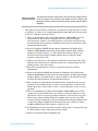
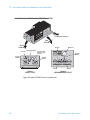
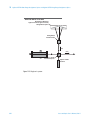
17 Beam-Directing Optics
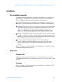
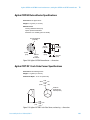
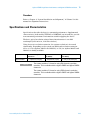
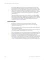
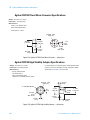
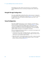
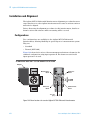
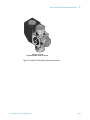
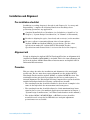
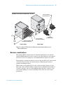
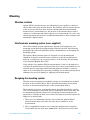
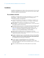
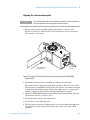
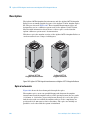
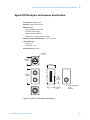
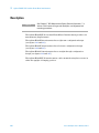
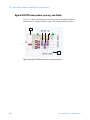
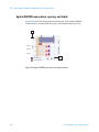
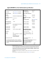
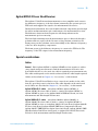
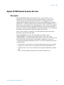
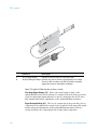
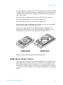
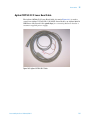
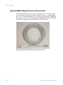
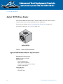
Agilent 10707A Beam Bender
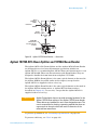
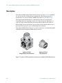
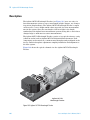
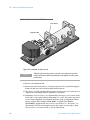
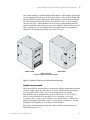
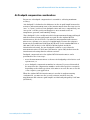
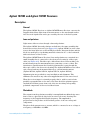
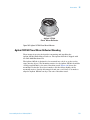
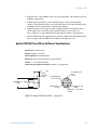
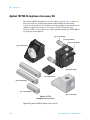
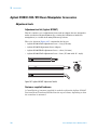
The Agilent 10707A Beam Bender contains a 100% reflectance mirror which
turns the direction of an incoming laser beam 90 degrees.
To preserve polarization, see “Preventing Depolarization" on page 362.
To preserve efficiency, see “Note" on page 362.
BEAM
B
E
N
D
ER
10
70
7A
Agilent 10707A
Beam Bender
Figure 89
Agilent 10707A Beam Bender
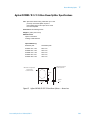
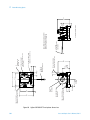
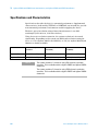
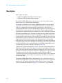
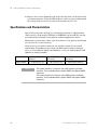
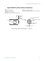
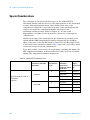
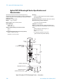
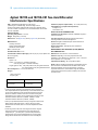
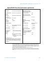
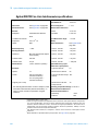
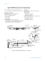
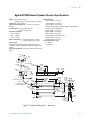
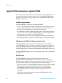
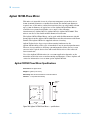
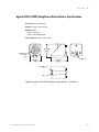
Agilent 10707A Beam Bender Specifications
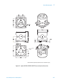
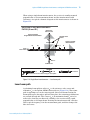
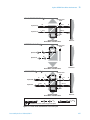
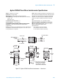
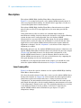
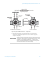
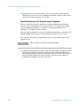
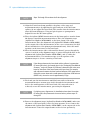
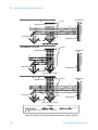
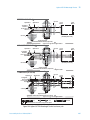
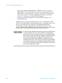
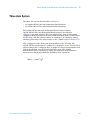
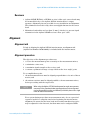
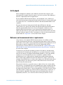
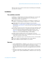
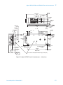
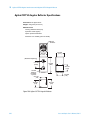
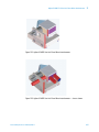
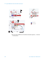
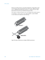
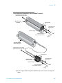
Dimensions: See drawings below.
Weight: 58 grams (2.1 ounces)
Materials Used:
Housing: Stainless Steel
Optics: Optical Grade Glass
Adhesives: Low Volatility (Vacuum Grade)
Coatings: Hard Dielectric
Optical Efficiency:
Typical: 99%
Worst Case: 98%
372
Laser and Optics User’s Manual, Vol. II
Beam-Directing Optics
17
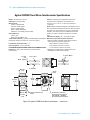
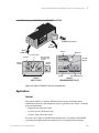
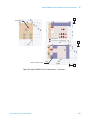
#4-40
(0.15 Deep)
2 Sides
25.4 mm
(1.0)
Center Line
19.6 mm
(0.77) Typ
25.4 mm
(1.0)
#6-32 UNC
Thru Clearance
For #4 or (2.5 mm)
2 Places
AM
BE
19.6 mm
(0.77) Typ
10707A
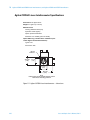
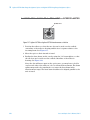
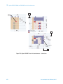
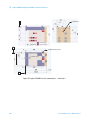
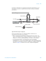
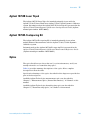
Figure 90
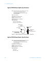
Agilent 10707A Beam Bender — dimensions
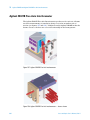
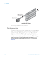
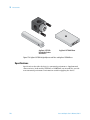
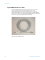
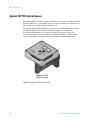
Agilent 10725A 50% Beam Splitter and 10726A Beam Bender
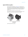
The Agilent 10725A 50% Beam Splitter and the Agilent 10726A Beam Bender
are designed for use in a laser measurement system that includes an
Agilent 10735A or a standard Agilent 10736A Three-axis Interferometer or an
Agilent 10736A-001 Three-axis Interferometer with Beam Bender. They are
designed to handle the 9 mm beam from an Agilent 5517C-009.
The Agilent 10725A Beam Splitter is the same optical element as that used in
the Agilent 10701A (described earlier in this chapter) except that the
Agilent 10725A is supplied without a housing.
The Agilent 10726A Beam Bender is the same optical element as that used in
the Agilent 10772A turning mirror or Agilent 10773A flatness mirror,
described in Chapter 36, “Accessories,” except that the Agilent 10726A is
supplied without a housing.
CAUTION
Agilent Technologies does not provide mounting hardware for the
Agilent 10725A beam splitter or the Agilent 10726A beam bender.
These devices are intended for use in user-designed mounts. The
user is responsible for devising a mounting method that does not
cause stress in the optic which will result in distortion of the
reflected laser wavefronts.
To preserve polarization, see “Preventing Depolarization" on page 362.
To preserve efficiency, see “Note" on page 362.
Laser and Optics User’s Manual, Vol. II
373
17 Beam-Directing Optics
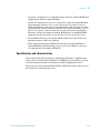
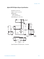
Agilent 10725A Beam Splitter Specifications
Use: Split a laser beam having a diameter up to 9 mm
(nominal). This beam splitter requires a
user-supplied mount. This optic can be made
vacuum compatible.
Type: Non-polarizing
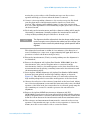
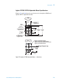
Dimensions: See drawings below.
Weight: 2 grams (0.07 ounce)
Materials Used: Optic, Fused silica
Optical Efficiency:
Typical: 45% (each beam)
Worst Case: 39% (each beam)
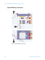
Beam Splitting
Coating
(Incident Face)
19.3 mm Dia
(0.76)
2.41 mm
(.09)
Anti-reflection
Coating
(Transmitting Face)
Minimum Clear Aperture
16.50 mm (0.65)
Concentric to O.D.
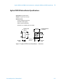
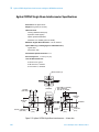
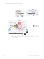
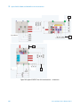
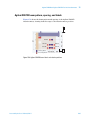
Figure 91
Agilent 10725A 9mm Laser Beam Splitter — dimensions
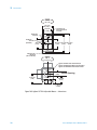
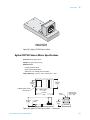
Agilent 10726A Beam Bender Specifications
Use: Bend a laser beam having a diameter up to 9 mm
(nominal). This beam bender requires a
user-supplied mount. This optic can be made
vacuum compatible.
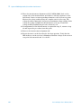
Dimensions: See drawings below.
Weight: 10 grams (0.35 ounce)
Materials Used: Optic, Fused silica
Optical Efficiency:
Typical: 99%
Worst Case: 98%
374
Laser and Optics User’s Manual, Vol. II
Beam-Directing Optics
17
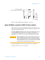
Minimum Clear Aperture
Central 19.05 mm (0.75) × 26.92 mm (1.06)
30.48 mm
(1.20)
45°
22.0 mm
(0.87)
5.59
(0.22)
7.62
(0.30)
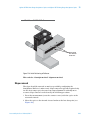
Figure 92
Agilent 10726A 9mm Laser Beam Bender — dimensions
Agilent 10725B 4% and Agilent 10725C 15% Beam Splitters
Each of these bare optics, non-polarizing beam splitter is designed for use in
multiaxis laser measurement systems. They are designed to handle the 9 mm
beam from an Agilent 5517C-009.
The Agilent 10725B Beam Splitter is the same optical element as that used in
the Agilent 10700B (described earlier in this chapter) except that the
Agilent 10725B is supplied without a housing. Likewise, the Agilent 10725C
Beam Splitter is the same optic as that used in the 10700C minus housing.
CAUTION
Agilent Technologies does not provide mounting hardware for the
Agilent 10725B/C beam splitters. These devices are intended for
use in user-designed mounts. The user is responsible for devising a
mounting method that does not cause stress in the optic which will
result in distortion of the reflected laser wavefronts.
To preserve polarization, see “Preventing Depolarization" on page 362.
To preserve efficiency, see “Note" on page 362.
Laser and Optics User’s Manual, Vol. II
375
17 Beam-Directing Optics
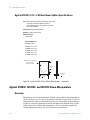
Agilent 10725B/C Beam Splitter Specifications
Use: Split a laser beam having a diameter up to 9 mm
(nominal). This beam splitter requires a
user-supplied mount. This optic can be made
vacuum compatible.
Type: Non-polarizing
Dimensions: See drawings below.
Weight: 2 grams (0.07 ounce)
Materials Used: Optic, Fused silica
Optical Efficiency:
10725B —
Reflected Path: Typical 4%; worst case 3%
Transmitted Path: Typical 95%; worst case 94%
10725C —
Reflected Path: Typical 15%; worst case 9%
Transmitted Path: Typical 84%; worst case 78%
Beam Splitting
Coating
(Incident Face)
19.3 mm Dia
(0.76)
2.41 mm
(.09)
Anti-reflection
Coating
(Transmitting Face)
Minimum Clear Aperture
16.50 mm (0.65)
Concentric to O.D.
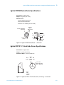
Figure 93
376
Agilent 10725B/C 9mm Laser Beam Splitter — dimensions
Laser and Optics User’s Manual, Vol. II
Beam-Directing Optics
17
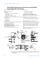
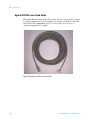
Agilent E1833C/E/G/J/M Bare Beam Splitter
The Agilent E1833C/E/G/J/M are bare beam splitters that can be used for
routing the laser beam throughout the laser interferometer system. These
splitters require user-supplied mounts and have a clear apeture of 29 mm
× 19 mm.
The Agilent E1833C 15% Bare Beam Splitter nominally reflects 15% of the laser
beam intensity perpendicular to the original beam direction while the 85%
continues through the optic.
The Agilent E1833E 33% Bare Beam Splitter nominally reflects one-third (or
33%) of the laser beam intensity perpendicular to the original beam direction
while the remaining two-thirds continues through the optic.
The Agilent E1833G 50% Bare Beam Splitter nominally reflects 50% of the
laser beam intensity perpendicular to the original beam direction while the
remaining 50% continues through the optic.
The Agilent E1833J 67% Bare Beam Splitter nominally reflects 67% of the laser
beam intensity perpendicular to the original beam direction while the
remaining 33% continues through the optic.
The Agilent E1833M 100% Bare Beam Splitter (beam bender) nominally
reflects 100% of the laser beam intensity perpendicular to the original beam.
To preserve polarization, see “Preventing Depolarization" on page 362.
To preserve efficiency, see “Note" on page 362.
Laser and Optics User’s Manual, Vol. II
377
17 Beam-Directing Optics
Agilent E1833C/E/G/J/M Bare Beam Splitter Specifications
Use: Split a laser beam having a diameter up to 9 mm
(nominal). This beam splitter requires a
user-supplied mount. This optic can be made
vacuum compatible.
Dimensions: See drawings below.
Weight: 2 grams (0.07 ounce)
Materials Used:
Optics: BK7
Optical Efficiency:
Reflective path:
E1833C: 15% ± 5%
E1833E: 33% ± 5%
E1833G: 50% ± 5%
E1833J: 67% ± 5%
E1833M: 100% −5%
Minimum clear aperture
central elipse
29 mm x 19 mm
33.0 mm
+ .01
23.0 mm
+ .01
Figure 94
6.38 mm
+ .01
Agilent E1833C/E/G/J/M Bare Beam Splitter — dimensions
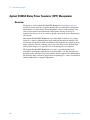
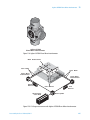
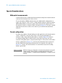
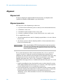
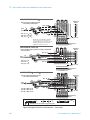
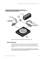
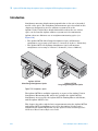
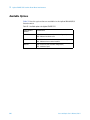
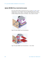
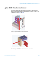
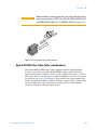
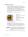
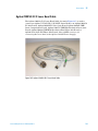
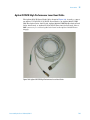
Agilent N1203C, N1204C, and N1207C Beam Manipulators
Overview
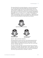
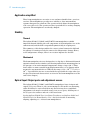
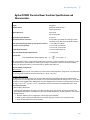
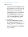
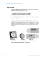
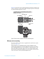
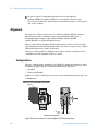
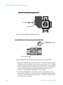
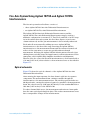
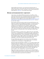
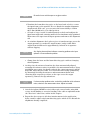
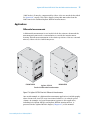
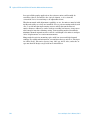
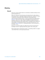
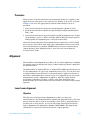
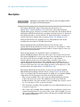
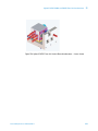
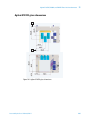
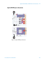
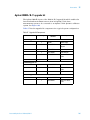
The purpose of the Agilent N1203C, N1204C, and N1207C beam manipulators
(shown in Figure 95) is to precisely bend or translate a laser beam to achieve
sub-nanometer distance measurements. The precise bending and translating
results in a properly aligned laser beam. An improperly aligned laser system
will produce errors. The beam manipulators are very useful in rapid laser
system alignment used for precision distance measurements.
378
Laser and Optics User’s Manual, Vol. II
Beam-Directing Optics
17
The Agilent N1203C Precision Beam Translator is a precision optical mount
for a refracting window. The Agilent N1204C Precision Horizontal Beam
Bender and Agilent N1207C Precision Vertical Beam Bender are precision
optical mounts for bending mirrors. These products are designed to provide
high resolution positioning of laser beams for precise distance measurements
by the application of removable tooling (see “Agilent N1203C/04C/07C Beam
Manipulator Accessories” in Chapter 36, “Accessories,” of this manual for
details on the adjustment tool kit). Once the adjustment is completed and tools
removed, this mount will provide long-term stability of the initial setting in the
presence of specified thermal, shock and vibration environments.
OR
03CC
NN12
1203
L
NS
AT
PRE
C I SI O N B E A M
TRA
Agilent N1203C Precision Beam Translator
03CC
NN12
1204
07C
OR
BE
N
DER
N12
L
NS
C I SI O N B E A M
TRA
Agilent N1204C Precision
Horizontal Beam Bender
Figure 95
BEA
M
AT
PRE
PRE
C I S I O N V E R TI
CAL
Agilent N1207C Precision
Vertical Beam Bender
Agilent precision beam manipulators
The Agilent N1203C translates the beam so that the measurement beam is
positioned where you want it on the stage mirror. The offset laser beam
remains parallel to the original beam direction. The translator is useful
whenever a high precision distance measurement with a laser is performed
because it can reduce Abbé error.
The Agilent N1204C and N1207C steer the laser beam in angle in either the
horizontal or vertical plane. The beam bender’s optical component (a mirror)
is intended to turn the laser beam 90° relative to the original beam direction.
The beam bender is useful whenever high precision distance measurements
with a laser is performed because it can reduce cosine error.
Laser and Optics User’s Manual, Vol. II
379
17 Beam-Directing Optics
Application simplified
These beam manipulators are easier to use and more durable than previous
versions. The manipulators provide more stability to laser measurement
systems than previous solutions. The operator merely aligns the manipulator
with removable tools. The operator need not perform the secondary clamping
operation. The manipulators are already clamped.
Stability
Thermal
The Agilent N1203C, N1204C, and N1207C beam manipulators exhibit
improved thermal stability since all components of the manipulator are of the
same material, and the ball is suspended symmetrically in a spring nest.
The symmetry of this design enables the contact points between the ball and
the springs to remain precisely the same as the temperature changes. Hence,
as the temperature changes, there is no rotation imparted to the ball.
Mechanical
The beam manipulator feet are designed not to slip due to differential thermal
expansion between the stainless steel housing and an Invar mounting plate in
the presence of an environmental temperature change of up to 20° C. Thus,
there will be no unrecoverable beam displacement due to foot slippage when
mounted to any material whose CTE is in the range of 1.6 × 10⁻⁶/° C to 21.8 ×
10-6/° C provided the feet are secured with the specified bolt torque value (see
the specifications and characteristic sections for the beam manipulators at the
end of this chapter).
Optical Input/Output ports and adjustment access
The Agilent N1203C, N1204C, and N1207C manipulators have six input and
output (I/O) ports. There is only one mounting face. From this one mounting,
either horizontal or vertical bends in any direction may be accomplished.
Adjustment tools may be attached at any of ten access ports, allowing two of
the I/O ports for entrance and exit of the laser beam.
See the Agilent N1203C Precision Beam Translator and Agilent 1204C and
N1207C Precision Beam Benders User’s Guide for details on mounting,
aligning, adjusting, etc. of these beam manipulators.
380
Laser and Optics User’s Manual, Vol. II
Beam-Directing Optics
17
Agilent N1203C Precision Beam Translator Specifications and
Characteristics
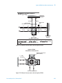
Dimensions:
See Figure 96.
Weight:
920 grams
Materials Used:
Martensitic stainless steel
Optical grade glass
Optical Efficiency:
99% typical
98.7% Worst case
Input/Output Clear Aperture:
φ 19.0 mm
Input Beam Position Tolerance:
± 5mm (Note: input beam de-centering may limit
translation range. See range specification below.)
Beam Translation Range (from input at normal incidence
on center of clear aperture):
± 3 mm with φ 9 mm beam
± 4.0 mm with φ 6 mm beam
± 4.4 mm with φ 3 mm beam
Angular Beam Deviation:
± 10 microradian maximum
Beam Translation Sensitivity/Resolution:
1.0 micrometer
Thermal Drift:
ΔD
Translated Beam Displacement per ° C = -------- = 100 nm per ° C
ΔT
Shift of output beam position is theroretically possible in the presence of a thermal gradient in the assembly, but the
refractive translator is quite insensitive to small angular changes. Nevertheless, even these miniscule shifts are
transitory and the original position is recovered when the gradient has settled out.
Thermal Stability of Alignment:
Ball to Housing
Beam position alignment is fully recoverable over a slow environmental temperature change of 20° C provided there
are no sharp thermal gradients within the assembly (i.e., ΔD/ΔT ~20° C/hr.)
Housing to Mounting Plate
The Manipulator feet are designed not to slip due to differential thermal expansion between the stainless steel
housing and an Invar mounting plate in the presence of an environmental temperature change of 20° C. Thus, there
should be no unrecoverable beam displacement due to foot slippage when mounted to any material whose CTE is in
the range of 1.6 × 10⁻⁶/° C to 21.8 × 10⁻⁶/° C provided the feet are secured with the specified bolt torque value.
Resonant Frequencies:
Ball and Spring Suspension
The laser beam Manipulator comprises a very stiff, nonlinear spring-mass system. At shock levels below the
shock damage threshold it is not possible to excite a free vibration resonance in the ball suspension. This is due to
three phenomena:
1. Prestress stiffening due to compression of the springs in final assembly.
2. Stiffening due to geometrical deformation of the beam springs as a result of the compressive load.
3. Frictional damping between ball and springs.
Laser and Optics User’s Manual, Vol. II
381
17 Beam-Directing Optics
Resonant Frequencies (Continued):
Ball and Spring Suspension (Continued)
The natural resonance of the spring-mass system (350 Hz) is completely supressed by these effects.
The first FFT measured resonance in the assembly is at 3.5 kHz, which is the Ball itself. The next resonance is at
3.7 kHz, which is the Housing:
Thus, there is no resonance which could disturb laser beam alignment or position in the operating environment.
Shock:
Operating: 40 g, half sine, 2.9 ms
A shock load of 40 g, half sine, 2.9 ms will not disturb the alignment of the Ball, Refractive Translator or laser
beam.
Non Operating: 60 g, half sine, 2.9 ms
A shock load of 60 g, half sine, 2.9 ms will not damage the Manipulator components, but may disturb alignment
of the Ball.
Recommended Mounting Screws:
Four screws M5× 20 long Alloy Steel; Grade 12.9: Seating Torque is 5 N.m if Cadmium plated, or 6.5 N.m if
unplated.
OR
Four screws 10-32 UNF × .75 inches long Alloy Steel: Seating Torque is 39 in-lbs if Cadmium plated, or
51 in-lbs if unplated.
Adjustment Tooling: 5 mm Hex-key wrench
382
Laser and Optics User’s Manual, Vol. II
17
Beam-Directing Optics
Agilent N1204C Precision Horizontal Beam Bender Specifications and
Characteristics
Dimensions:
See Figure 96.
Weight:
920 grams
Materials Used:
Martensitic stainless steel
Optical grade glass
Optical Efficiency:
99% typical
97.5% Worst case
Input/Output Clear Aperture:
φ 13.0 mm
Input Beam Position Tolerance:
± 1.6 mm for φ 9mm beam
Angular Beam Steering Range (from nominal
90°, φ 9 mm beam centered on φ 13 mm Aperture):
Yaw: ± 6° (using Adjustment Lever and adapter at φ25 mm
port )
Pitch: ± 3° (using Adjustment Lever and adapter at φ25 mm port)
Yaw: ± 1°
(using Adjustment Lever only, at φ9 mm port )
Pitch: ± 0.7° (using Adjustment Lever only, at φ9mm port)
Angular Adjustment Sensitivity and Beam Steering
Resolution:
10 – 15 µradians (better with operator patience)
Thermal Drift:
With the Manipulator feet on a horizontal surface:
Pitch
Yaw
ΔP
------- = 5 μrad per ° C
ΔT
Δ
Y
-------- = 0.5 μrad per ° C
ΔT
Drift of beam steering angle can occur in the presence of thermal gradients in the Manipulator assembly. This drift
is transitory and alignment is recovered when the gradient has settled out.
Thermal Stability of Alignment:
Ball to Housing
Beam angle steering alignment is recoverable over a slow environmental temperature change of 20° C provided
there are no sharp thermal gradients within the assembly (i.e., ΔT/Δt ~20° C/hr.)
Housing to Mounting Plate
The Manipulator feet are designed not to slip due to differential thermal expansion between the stainless steel
housing and an Invar mounting plate in the presence of an environmental temperature change of 20° C. Thus,
there should be no unrecoverable misalignment due to foot slippage when mounted to any material whose CTE
is in the range of 1.6 × 10⁻⁶/° C to 21.8 × 10⁻⁶/° C provided the feet are secured with the specified bolt torque
value.
Laser and Optics User’s Manual, Vol. II
383
17 Beam-Directing Optics
Resonant Frequencies:
Ball-Spring Suspension
The laser beam Manipulator comprises a very stiff, nonlinear spring-mass system. At shock levels below the
shock damage threshold it is not possible to excite a free vibration resonance in the ball suspension. This is due
to three phenomena:
1. Prestress stiffening due to compression of the springs in final assembly.
2. Stiffening due to geometrical deformation of the beam springs as a result of the compressive load.
3. Frictional damping between ball and springs.
The natural resonance of the spring-mass system (350 Hz) is completely supressed by these effects.
The first FFT measured resonance in the assembly is at 3.5 kHz, which is the Ball itself. The next resonance is at
3.7 kHz, which is the Housing:
Thus, there is no resonance which could disturb laser beam alignment or position in the operating environment.
Mirror-Spring Suspension
The Mirror is held against three mounting pads machined into the Ball by spring forces opposite the pads. This
spring mass system is not free to vibrate unless the Mirror is separated from the contact with pads. It requires a
shock load of 280 g (far in excess of the shock damage threshold) to separate the Mirror from the Ball. Thus, it is
not possible in practice to excite a resonance.
Note: The calculated resonance for the Mirror./Spring system if the ball were free to oscillate is 340 Hz.
Shock
Operating: 40 g, half sine, 2.9 ms
A shock load of 40 g, half sine, 2.9 ms will not disturb the alignment of the Ball, Mirror or laser beam.
Non Operating: 60 g, half sine, 2.9 ms
A shock load of 60 g, half sine, 2.9 ms will not damage the Manipulator components, but may disturb alignment.
Recommended Mounting Screws:
Four screws M5× 20 long Alloy Steel; Grade 12.9: Seating Torque is 5 N.m if Cadmium plated, or 6.5 N.m if
unplated.
OR
Four screws 10-32 UNF × .75 inches long Alloy Steel: Seating Torque is 39 in-lbs if Cadmium plated, or
51 in-lbs if unplated.
Angular Adjustment Tool Leverage: Lever rotatation : ball rotation = 2.9 : 1
384
Laser and Optics User’s Manual, Vol. II
17
Beam-Directing Optics
Agilent N1207C Precision Vertical Beam Bender Specifications and
Characteristics
Dimensions:
See Figure 96.
Weight:
920 grams
Materials Used:
Martensitic stainless steel
Optical grade glass
Optical Efficiency:
99% typical
97.5% Worst case
Input/Output Clear Aperture:
φ 13.0 mm
Input Beam Position Tolerance:
± 1.6 mm for φ 9mm beam
Angular Beam Steering Range (from nominal
90°, φ 9 mm beam centered on φ 13 mm Aperture):
Yaw: ± 3° (using Adjustment Lever and adapter at φ25 mm
port )
Pitch: ± 6° (using Adjustment Lever and adapter at φ25 mm port)
Yaw: ± 0.7°
(using Adjustment Lever only, at φ9 mm port )
Pitch: ± 1° (using Adjustment Lever only, at φ9mm port)
Angular Adjustment Sensitivity and Beam Steering
Resolution:
10 – 15 µradians (better with operator patience)
Thermal Drift:
With the Manipulator feet on a horizontal surface:
Pitch
Yaw
ΔP
------- = 5 μrad per ° C
ΔT
Δ
Y
-------- = 0.5 μrad per ° C
ΔT
Drift of beam steering angle can occur in the presence of thermal gradients in the Manipulator assembly. This
drift is transitory and alignment is recovered when the gradient has settled out.
Thermal Stability of Alignment:
Ball to Housing
Beam angle steering alignment is recoverable over a slow environmental temperature change of 20° C provided
there are no sharp thermal gradients within the assembly (i.e., ΔT/Δt ~20° C/hr.)
Housing to Mounting Plate
The Manipulator feet are designed not to slip due to differential thermal expansion between the stainless steel
housing and an Invar mounting plate in the presence of an environmental temperature change of 20° C. Thus,
there should be no unrecoverable misalignment due to foot slippage when mounted to any material whose CTE
is in the range of 1.6 × 10⁻⁶/° C to 21.8 × 10⁻⁶/° C provided the feet are secured with the specified bolt torque
value.
Laser and Optics User’s Manual, Vol. II
385
17 Beam-Directing Optics
Resonant Frequencies:
Ball-Spring Suspension
The laser beam Manipulator comprises a very stiff, nonlinear spring-mass system. At shock levels below the
shock damage threshold it is not possible to excite a free vibration resonance in the ball suspension. This is due
to three phenomena:
1. Prestress stiffening due to compression of the springs in final assembly.
2. Stiffening due to geometrical deformation of the beam springs as a result of the compressive load.
3. Frictional damping between ball and springs.
The natural resonance of the spring-mass system (350 Hz) is completely supressed by these effects.
The first FFT measured resonance in the assembly is at 3.5 kHz, which is the Ball itself. The next resonance is at
3.7 kHz, which is the Housing:
Thus, there is no resonance which could disturb laser beam alignment or position in the operating environment.
Mirror-Spring Suspension
The Mirror is held against three mounting pads machined into the Ball by spring forces opposite the pads. This
spring mass system is not free to vibrate unless the Mirror is separated from the contact with pads. It requires a
shock load of 280 g (far in excess of the shock damage threshold) to separate the Mirror from the Ball. Thus, it is
not possible in practice to excite a resonance.
Note: The calculated resonance for the Mirror./Spring system if the ball were free to oscillate is 340 Hz.
Shock
Operating: 40 g, half sine, 2.9 ms
A shock load of 40 g, half sine, 2.9 ms will not disturb the alignment of the Ball, Mirror or laser beam.
Non Operating: 60 g, half sine, 2.9 ms
A shock load of 60 g, half sine, 2.9 ms will not damage the Manipulator components, but may disturb alignment.
Recommended Mounting Screws:
Four screws M5× 20 long Alloy Steel; Grade 12.9: Seating Torque is 5 N.m if Cadmium plated, or 6.5 N.m if
unplated.
OR
Four screws 10-32 UNF × .75 inches long Alloy Steel: Seating Torque is 39 in-lbs if Cadmium plated, or
51 in-lbs if unplated.
Angular Adjustment Tool Leverage: Lever rotatation : ball rotation = 2.9 : 1
386
Laser and Optics User’s Manual, Vol. II
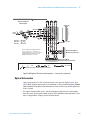
Beam-Directing Optics
2X
25.0
17
2X
25.0
25.0
Ø 5.80
4X
25.0
Ø 59.9
61.5
2.6
31.5
12.2
31.4
+0.05
Ø 25.45 -0.0
6X
62.7
31.4
62.7
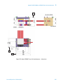
Unless otherwise specified, dimensions are in millimeters (mm).
Figure 96
Agilent N1203C/N1204C/N1207C beam manipulator dimensions
Laser and Optics User’s Manual, Vol. II
387
17 Beam-Directing Optics
Agilent N1208C/D/E/F/G Bare Beam Splitter
The Agilent N1208C/D/E/F/G are bare beam splitters that can be used for
routing the laser beam throughout the laser interferometer system. These
splitters require user-supplied mounts and can handle beam diameters up to
9 mm (nominal).
The Agilent N1208C 33% Bare Beam Splitter nominally reflects one-third (or
33%) of the laser beam intensity perpendicular to the original beam direction
while the remaining two-thirds continues through the optic.
The Agilent N1208D 40% Bare Beam Splitter nominally reflects 40% of the
laser beam intensity perpendicular to the original beam direction while the
remaining 60% continues through the optic.
The Agilent N1208E 50% Bare Beam Splitter nominally reflects 50% of the
laser beam intensity perpendicular to the original beam direction while the
remaining 50% continues through the optic.
The Agilent N1208F 66% Bare Beam Splitter nominally reflects 66% of the laser
beam intensity perpendicular to the original beam direction while the
remaining 34% continues through the optic.
The Agilent N1208G 60% Bare Beam Splitter nominally reflects 60% of the
laser beam intensity perpendicular to the original beam direction while the
remaining 40% continues through the optic.
To preserve polarization, see “Preventing Depolarization" on page 362.
To preserve efficiency, see “Note" on page 362.
388
Laser and Optics User’s Manual, Vol. II
Beam-Directing Optics
17
Agilent N1208C/D/E/F/G Bare Beam Splitter Specifications
Use: Split a laser beam having a diameter up to 9 mm
(nominal). This beam splitter requires a
user-supplied mount. This optic can be made
vacuum compatible.
Dimensions: See drawings below.
Weight: 2 grams (0.07 ounce)
Materials Used:
Optics: Fused silica
Coatings: Hard Dielectric
Optical Efficiency:
Reflective path:
Transmitted path:
N1208C: 33% ± 6%
66% ± 6%
N1208D: 40% ± 6%
56% ± 6%
N1208E: 50% ± 6%
49% ± 6%
N1208F: 66% ± 6%
33% ± 6%
N1208G: 60% ± 6%
39% ± 6%
All edges beveled
045 x 0.35 mm
Minimum clear aperture
central elipse
15 mm x 21 mm
29.0 mm
+ 0.1
21.0 mm
+ 0.1
Figure 97
6.7 mm
+ 0.1
Agilent N1208C/D/E/F/G Bare Beam Splitter — dimensions
Laser and Optics User’s Manual, Vol. II
389
17 Beam-Directing Optics
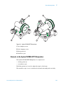
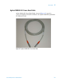
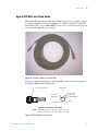
Agilent N1209A Risley Prism Translator (RPT) Manipulator
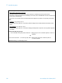
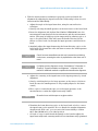
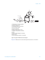
Overview
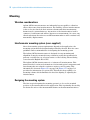
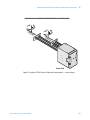
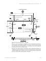
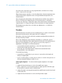
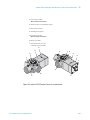
The purpose of the Agilent N1209A RPT Manipulator (see Figure 98) is to
provide you with a means of quickly making precise translation and angular
adjustments on a laser beam. This manipulator can precisely translate and
steer a laser beam for measurements that require extreme accuracy in
applications where you do not want to spend a great deal of time aligning the
laser beam.
The Agilent N1209A RPT Manipulator provides high resolution over a large
range in a compact, lightweight package with high mechanical stability. The
laser beam can quickly be bent and translated by elements in a single package,
using separate controls, enabling you to place the beam at the desired angle
and location in space. No special tools or mounting pins are required.
The Agilent N1209A RPT Manipulator is easy to use and provides both
translation and angular adjustments at an affordable cost. The transmissive
design provides excellent long-term stability during temperature and humidity
fluctuations and is suited for applications requiring up to 3 mm of translation
and 18 milliradians of angular adjustment.
390
Laser and Optics User’s Manual, Vol. II
Beam-Directing Optics
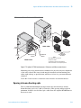
3
2
1
17
4
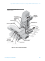
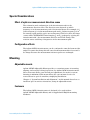
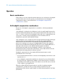
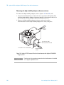
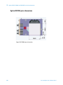
Figure 98
Agilent N1209A RPT Manipulator
1 Yaw clamping screw
2 Pitch clamping screw
3 Risley prism set
4 Translator optic
Elements in the Agilent N1209A RPT Manipulator
The Agilent N1209A RPT Manipulator is comprised of:
• a Risley prism set
• a translator optic
The Risley prism set is used to adjust the angle of the beam.
The translator optic is set to translate the beam horizontally and vertically.
Laser and Optics User’s Manual, Vol. II
391
17 Beam-Directing Optics
Thermal stability
The RPT manipulator can be fastened to most materials without concern for
the difference between material thermal expansion coefficients due to the
transmissive design.
Optical input/output ports and adjustment access
The Agilent N1209A RPT Manipulator has one input port and one output port.
There is only one mounting face. An adjustment tool is used to adjust the pitch
and yaw of the translator optic. The Risley prism set is adjusted by hand.
Adjustment tools
Customer-supplied hardware
• 4 mm hex-key wrench
• 2 mm hex-key wrench
A customer-supplied 4 mm hex-key wrench is needed to adjust the pitch and
yaw of the translator optic. A 2 mm hex-key wrench is used to tighten the
locking screws after making adjustments.
See the Agilent N1209A Risley Prism Translator (RPT) Manipulator User’s
Guide for details on mounting, aligning, adjusting, etc. of this beam
manipulator.
392
Laser and Optics User’s Manual, Vol. II
Beam-Directing Optics
17
Agilent N1209A RPT Manipulator Specifications
Physical Characteristics
Dimensions
See Figure 99.
Weight
350 grams
Resonant Frequency
>500 Hz
Material
Glass
BK7
Metal
416 stainless, passivated
Thermal Drift
Translation
<100 nm/°C
Angle
<10 mradians/°C
Optical Efficiency
>95%
Risley Prism Clear Aperture
16 mm
Translator Clear Aperture
19 mm
Beam Translation Range
± 3 mm radial
Beam Translation Resolution
20 microns
Maximum Angular Beam
Deviation
18 milliradians
Angular Beam Resolution
<30 microradians
Recommended Mounting Screws
Four screws M5× 20 long Alloy
Steel; Grade 12.9
Seating Torque is 5 N.m if Cadmium plated, or 6.5 N.m if unplated.
OR
Four screws 10-32 UNF × 0.75 Seating Torque is 39 in-lbs if Cadmium plated, or 51 in-lbs if
inches long Alloy Steel
unplated.
Adjustment Tooling
4 mm and 2 mm hex-key wrenches
Locking Screw Torque
M2.5 screws at 0.56N.m (5 in-lbs)
Laser and Optics User’s Manual, Vol. II
393
394
Figure 99
15.0
CLEAR
APERTURE
5.0
50.0
5.0
3.2
13.8
YAW LOCKING SCREW
(REQUIRES 2mm HEX TOOL)
KNURLED EDGE FOR
BETTER GRIP
60.0
YAW ADJUSTMENT
(REQUIRES 4mm HEX TOOL)
30.0
TO BEAM
CENTER
50.0
60.0
7.3
31.5
TO BEAM
CENTER
49.7
PITCH LOCKING SCREW
(REQUIRES 2mm HEX TOOL)
+/- 18 mrad
MAX BEAM
ANGLE CORRECTION
10.3
13.4
WEDGE LOCKING SCREW
(REQUIRES 2mm HEX TOOL)
PITCH ADJUSTMENT
(REQUIRES 4mm HEX TOOL OR
DIA. 4.55 PIN)
5.7
CLEARANCE FOR
M5X16mm 4X
+/-18 mrad
MAX BEAM ANGLE
CORRECTION
+/-3mm
RADIAL BEAM TRANSLATION
ADJUSTMENTS AND LOCKING SCREWS
REQUIRE ADDITIONAL SPACE FOR
ACCESS NOT SHOWN ON DRAWING
52.7
17 Beam-Directing Optics
Agilent N1209A RPT manipulator dimensions
Laser and Optics User’s Manual, Vol. II
Agilent Laser and Optics
User’s Manual Volume II
18
Agilent 10702A and 10766A Linear
Interferometers, and Agilent 10703A and
10767 Retroreflectors
Introduction, 396
Description, 396
Laser Beam Path, 401
Special Considerations, 403
Mounting, 404
Installation, 405
Specifications and Characteristics, 406
Agilent Technologies
395
18 Agilent 10702A and 10766A Linear Interferometers, and Agilent 10703A and 10767 Retroreflectors
Introduction
This chapter describes:
• the Agilent 10702A Linear Interferometer, including the
Agilent 10702A-001 Linear Interferometer with Windows
• the Agilent 10703A Retroreflector
• the Agilent 10766A Linear Interferometer
• the Agilent 10767A Retroreflector
• use of the Agilent 10722A Plane Mirror Converter
• use of the Agilent 10723A High Stability Adapter
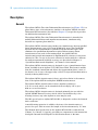
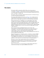
Description
LECTO
EF
F
R
T
R
INTE R
E
O
3A
70
10
RE
O
M
ET
70
R
BE
UM
LN
RIA
SE
ER
10
R
AR
R
L I NE
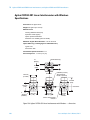
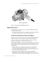
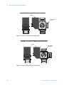
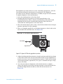
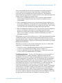
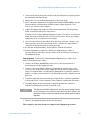
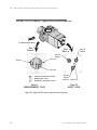
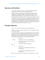
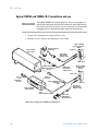
The Agilent 10702A Linear Interferometer (see Figure 100) and the
Agilent 10766A Linear Interferometer are intended for general-purpose
applications. Designed for use with a separate cube corner reflector, these
products are paired with the Agilent 10703A Retroreflector (see Figure 100) or
the Agilent 10767A Retroreflector (see Figure 103), respectively.
MADE
IN
U
.S
.A
2A
Agilent 10702A
Linear Interferometer
Agilent 10703A
Retroreflector
Agilent 10702A-001 Linear Interferometer
with Windows
Figure 100 Agilent 10702A Linear Interferometer Agilent 10702A-001 Linear Interferometer
with Windows
396
Laser and Optics User’s Manual, Vol. II
Agilent 10702A and 10766A Linear Interferometers, and Agilent 10703A and 10767 Retroreflectors
18
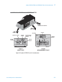
The Agilent 10702A Linear Interferometer, being the simplest interferometer,
should be used whenever possible. The measurement retroreflector for this
interferometer is the Agilent 10703A Retroreflector. Displacement is
measured between the interferometer and the retroreflector (cube corner).
Either one or both can move. If the linear interferometer must move, the
Agilent 10702A-001 Linear Interferometer with Windows must be used (see
Figure 101).
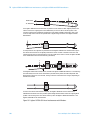
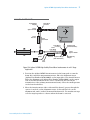
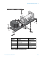
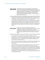
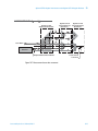
Normally, one optic is mounted on a moving part and the other is mounted on
a fixed part and the displacement between the two is measured. A diagram of
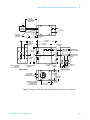
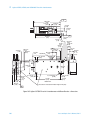
this is shown in Figure 102. Note that for multi-axis installations each axis
must be mechanically independent of the other. In other words, motion in the
Y-axis should have no effect on the alignment of the X-axis optics.
The Agilent 10766A Linear Interferometer (see Figure 103) is optically
identical to the Agilent 10702A-001 Linear Interferometer with Windows.
However, in order to withstand the handling and repeated installations of
calibrator-type applications, the Agilent 10766A interferometer has a
more-robust housing than the Agilent 10702A Option 001 interferometer
(which is intended for laser transducer measurement system applications).
Also, the Agilent 10766A interferometer has metric dimensions and metric
threads, whereas the Agilent 10702A interferometer does not.
Similarly, the Agilent 10767A Linear Retroreflector (see Figure 103) is
optically identical to the Agilent 10703A Retroreflector. However, in order to
withstand the handling and repeated installations of calibrator-type
applications, the Agilent 10767A retroreflector has a more-robust housing
than the Agilent 10703A retroreflector (which is intended for laser transducer
measurement system applications). Also, the Agilent 10767A interferometer
has metric dimensions and metric threads, whereas the Agilent 10703A
interferometer does not.
The Agilent 10722A Plane Mirror Converter (see Figure 104) is a quarter-wave
plate accessory for the Agilent 10702A interferometer. With the Agilent
10722A converter and an additional Agilent 10703A Retroreflector, the
Agilent 10702A interferometer can be converted to an Agilent 10706A Plane
Mirror Interferometer. This configuration allows measurements of axial
displacement of a plane mirror.
With the Agilent 10722A Plane Mirror Converter and the Agilent 10723A High
Stability Adapter, the Agilent 10702A Linear Interferometer can be converted
to an Agilent 10706B High Stability Plane Mirror Interferometer. This
configuration also allows measurements of axial displacement of a plane
mirror. The Agilent 10723A adapter is discussed in Chapter 20,
“Agilent 10706A Plane Mirror Interferometer,” of this manual. The
High-stability Plane Mirror Interferometer is described in Chapter 21 of this
manual.
Laser and Optics User’s Manual, Vol. II
397
18 Agilent 10702A and 10766A Linear Interferometers, and Agilent 10703A and 10767 Retroreflectors
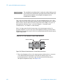
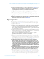
From Laser
θ
To Receiver
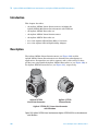
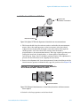
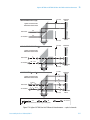
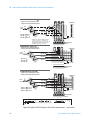
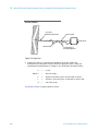
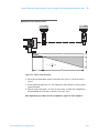
If the Agilent 10702A Linear Interferometer is placed in a beam which has been aligned parallel to the
motion of travel, the outgoing beam can be deflected by as much as 30 arc-minutes (θ ) due to the
incoming-outgoing beam parallelism specifications of the Agilent 10702A interferometer. This could
cause not only cosine error but also possible loss of signal during movement of the Agilent 10703A
Retroreflector.
θ
To compensate for this, alignment is performed with the Agilent 10702A Linear Interferometer in place.
This allows the laser beam to be aligned parallel to the motion of travel to minimize cosine error and
maximize signal. Since the incoming beam is now not parallel to the motion of travel, the Agilent 10702A
Linear Interferometer must remain stationary. (See below).
θ
δ
If the Agilent 10702A Linear Interferometer, instead of the Agilent 10703A Retroreflector, is moved during
the measurement, the beam in the measurement path will remain parallel, but will be displaced. This
displacement δ will occur at the receiver, causing a decrease and eventual loss of signal, depending on
the distance traveled.
If motion of the linear interferometer is required, the Agilent 10702A-001 Linear Interferometer
withWindows should be used. This provides special wedge windows which makes the outgoing beam
parallel to the incoming beam. This allows motion by either the Agilent 10703A Retroreflector or the
Agilent 10702A-001 Linear Interferometer.
Figure 101 Agilent 10702A-001 Linear Interferometer with Windows
398
Laser and Optics User’s Manual, Vol. II
Agilent 10702A and 10766A Linear Interferometers, and Agilent 10703A and 10767 Retroreflectors
18
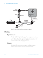
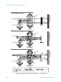
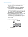
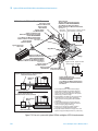
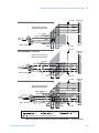
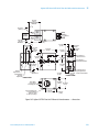
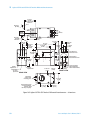
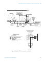
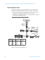
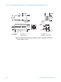
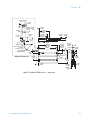
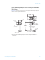
THREE-AXIS MACHINE TOOL
INSTALLATION
10703A
Retroreflector
(Attached to
Spindle Head,
moving)
MEASUREMENT #1
(Saddle Movement)
10780C Receiver
10702A
Linear Interferometer
(fixed)
10702A Linear
Interferometer (fixed)
10703A
Retroreflector
(Attached to Saddle, moving)
10780C Receiver
Power/
Reference
5517C
Laser
MEASUREMENT #2
(Head Movement)
10707A
Beam Bender
10700A
33% Splitter
D
D
SA
10703A
Retroreflector
(Attached to
Table, moving)
LE
10701A
50% Splitter
10707A Beam Benders
(Attached to Saddle)
10702A
Linear Interferometer
(Attached to Saddle)
MEASUREMENT #3
(Table Movement)
10780C Receiver
(Attached to Saddle)
Figure 102 Three-axis machine tool Installation
Laser and Optics User’s Manual, Vol. II
399
76
E
R
70
U
.S
S
1A
MADE
10
.A.
IA
L
N
U
M
B
E
R
10
T
ER
E
LIN
RO
7A
E
REFL CTOR
INTE
EAR RFERO
ME
T
AR RE
LIN
18 Agilent 10702A and 10766A Linear Interferometers, and Agilent 10703A and 10767 Retroreflectors
IN
2A
Agilent 10766A
Linear Interferometer
Agilent 10767A
Linear Retroreflector
Figure 103 Agilent 10766A Linear Interferometer and Agilent 10767A Linear Retroreflector
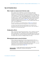
Agilent 10722A
Plane Mirror Converter
Figure 104 Agilent 10722A Plane Mirror Converter
400
Laser and Optics User’s Manual, Vol. II
Agilent 10702A and 10766A Linear Interferometers, and Agilent 10703A and 10767 Retroreflectors
18
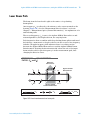
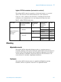
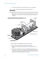
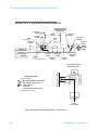
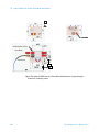
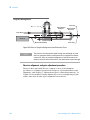
Laser Beam Path
The beam from the laser head is split at the surface of a polarizing
beam-splitter.
One frequency, fB, is reflected to the reference cube corner mounted on the
housing (Figure 105). See the “Measurement Direction Sense” section in
Chapter 5, “Measurement Optics (General Information),” for explanation of fA
and fB beam paths.
The second frequency, fA, is sent to the Agilent 10703A Retroreflector and
returned parallel to, but displaced from, the outgoing beam.
Both frequencies then recombine with the polarizing beam splitter and travel
back along a common axis to the photodetector in the receiver. One frequency
includes a Doppler frequency shift whenever there is a relative motion
between the Agilent 10703A Retroreflector and the Agilent 10702A Linear
Interferometer. Rotating the interferometer 90° about the axis of the input
beam switches which optical frequency is in the measurement path, thus
changing the direction sense.
REFERENCE and MEASUREMENT
PATHS (fA and fB)
Reference
Cube-Corner
fB
fA
fB
fA± Δ f
fB
fA
Agilent 10703A
Retroreflector
fA± Δ f
Agilent 10702A
Linear Interferometer
LEGEND
= fA
= fB
= fA and fB
Figure 105 Linear interferometer laser beam path
Laser and Optics User’s Manual, Vol. II
401
18 Agilent 10702A and 10766A Linear Interferometers, and Agilent 10703A and 10767 Retroreflectors
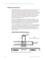
Differential measurements
A differential measurement is one in which both the reference beam and the
measurement beam travel to external reflectors (either cube corners or
mirrors) outside the interferometer housing. This allows measurement of the
relative positions of the two external mirrors, either or both of which may be
moving. Viewed another way, this allows measuring the motion of one reflector
relative to a reference datum elsewhere in the machine, external to the
interferometer itself. This is unlike the typical interferometer configuration
because usually the reference beam path length does not change; in
differential configurations, it can.
Take care during design and layout of a differential measurement to avoid
introduction of alignment errors, thermal or mechanical instabilities, and
potential deadpath problems. Both reflectors (reference and measurement)
should be of the same type (cube corner or plane mirror); this minimizes
thermal drift problems with ambient temperature changes.
To use an Agilent 10702A or Agilent 10766A interferometer in a differential
measurement configuration, the reference cube corner can simply be detached
from the interferometer housing and attached to the reference surface of
interest. This is shown in Figure 106. Be aware that all installation and
alignment requirements for the measurement reflector now apply also to the
reference reflector.
DIFFERENTIAL MEASUREMENT
Reference
Reflector
(see note)
fB± Δ fB
fA
fA± Δ fA
NOTE
Either reflector, or both, may move.
fB
fB
fA
fB± Δ fB
fA± Δ fA
Measurement
Reflector
(see note)
Agilent 10702A
Linear Interferometer
LEGEND
= fA
= fB
= fA and fB
Figure 106 Differential measurements with the Agilent 10702A
402
Laser and Optics User’s Manual, Vol. II
Agilent 10702A and 10766A Linear Interferometers, and Agilent 10703A and 10767 Retroreflectors
18
Special Considerations
Effect of optics on measurement direction sense
The orientation and configuration of the interferometers affects the
measurement direction sense. The direction sense depends on which
frequency is in the measurement path of the interferometer. For example, if f1
(lower frequency) is in the reference path and the optics are moving away from
each other, the fringe counts will be INCREASING. This corresponds to using
an Agilent 5517A, or Agilent 5517B/BL/C/D/DL/F Laser Head (mounting feet
in horizontal plane) with an Agilent 10702A Linear Interferometer mounted
with labels facing up and down (see Figure 105). Interchanging f1 and f2
(perhaps by rotating the interferometer 90°) in this example will result in the
fringe counts DECREASING.
The optical schematic for the interferometers, in Figure 105, shows the
reference and measurement laser beam paths for these interferometers.
As with the laser heads, when the interferometers are rotated 90°, the
measurement direction sense will change. This rotation causes switching of
frequencies in the measurement path.
Configuration effects
Many of the distance-measuring interferometers can be configured to turn the
beam at right angles. When configuring the linear, single-beam, and plane
mirror interferometers to turn the beam, the measurement direction sense will
be changed. This is because the measurement reference paths are switched on
the interferometers, therefore changing the direction sense.
Moving interferometer instead of reflector
When moving the interferometer instead of the measurement reflector is
required, the Agilent 10702A-001 (or Agilent 10766A) interferometer should
be used. In practice, for alignment reasons, these are two of the few
interferometers that can be moved while making measurements. For a detailed
explanation of the beam alignment problems involved with a
moving-interferometer setup, see Figure 101.
N O TE
Laser and Optics User’s Manual, Vol. II
If a right-angle beam bend is made through the Agilent 10702A
interferometer, it must be the fixed component.
403
18 Agilent 10702A and 10766A Linear Interferometers, and Agilent 10703A and 10767 Retroreflectors
Mounting
Vibration considerations
To achieve the highest possible measurement accuracy, be sure your
measurement system design and installation provide sufficient and
appropriate isolation of the optical components from the effects of vibration.
See Chapter 3, “System Design Considerations,” and Chapter 4, “System
Installation and Alignment,” in Volume I of this manual for more information.
Adjustable mounts
The optical elements inside these Agilent laser measurement system optics are
not precisely referenced to their housings. In most applications involving these
optics, a few simple alignments during system installation can usually provide
equal or better alignment than referencing the optics to their housings.
Therefore, slight positioning adjustments of the unreferenced interferometers,
beam splitters, and beam benders are needed for proper system alignment.
Positioning adjustments for the Agilent 10702A interferometer can be
provided by using an Agilent 10711A Adjustable Mount.
Positioning adjustments for the Agilent 10766A interferometer can be
provided by using an Agilent 10785A Height Adjuster and Post (a base plate
accessory, Agilent 10784A, for the post is available), where appropriate. These
mounting arrangements allow adjustment of pitch and yaw of any attached
optic. (Roll adjustment is typically not required, and can usually be avoided by
careful optical system layout.)
Fasteners
The Agilent 10702A interferometer is supplied with mounting screws to mount
it on the Agilent 10711A Adjustable Mount.
The Agilent 10785A Height Adjuster and Post, and the Agilent 10767A Linear
Retroreflector, include captive hardware necessary for mounting and aligning
the Agilent 10766A Laser Interferometer.
404
Laser and Optics User’s Manual, Vol. II
Agilent 10702A and 10766A Linear Interferometers, and Agilent 10703A and 10767 Retroreflectors
18
Installation
Pre-installation checklist
In addition to reading chapters 2 through 4, and Chapter 12, “Accuracy and
Repeatability,” (in Volume I of this manual), complete the following items
before installing a laser positioning system into any application.
Complete Beam Path Loss Calculation (see Calculation of signal loss” in
Chapter 3, “System Design Considerations,” in Volume I of this manual).
Determine the direction sense for each axis, based on the orientation of the
laser head, beam-directing optic, and interferometer. Enter the direction
sense for each axis into the measurement system electronics. (See
Chapter 16, “Laser Heads,” Chapter 11, “Principles of Operation,” and
Chapter 12, “Accuracy and Repeatability,” in Volume I of this manual.
Provide for aligning the optics, laser head, and receiver(s) on the machine.
(Ideally, you want to be able to translate beam in two directions and rotate
beam in two directions for each interferometer input. This typically takes
two adjustment optics with proper orientations.)
Be sure to allow for transmitted beam offset of beam splitters
(Agilent 10700A and Agilent 10701A) in your design. (See the offset
specifications under the “Specifications” heading at the end of this
chapter.)
Refer to Chapter 4, “System Installation and Alignment,” in Volume I of this
manual for installation instructions.
Alignment
Alignment aids
Alignment aids for these interferometers are listed in Chapter 4, “System
Installation and Alignment,” in Volume I and Chapter 36, “Accessories,” of this
manual.
Procedure
Refer to Chapter 4, “System Installation and Alignment,” in Volume I of this
manual for alignment instructions.
Laser and Optics User’s Manual, Vol. II
405
18 Agilent 10702A and 10766A Linear Interferometers, and Agilent 10703A and 10767 Retroreflectors
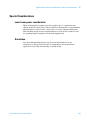
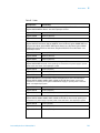
Specifications and Characteristics
Specifications describe the device’s warranted performance. Supplemental
characteristics (indicated by TYPICAL or NOMINAL) are intended to provide
non-warranted performance information useful in applying the device.
The basic optical resolution using a linear interferometer is one half
wavelength (0.316 micron, 12.26 microinches).
Using electronic resolution extension, the system resolution is increased
significantly. Depending on the system, an additional resolution extension
factor of 32 (for Agilent 10885A and 10895A) or 256 (for Agilent 10897B and
10898A) is usually available.
Interferometer
Fundamental Optical
Resolution
System Resolution 1
(see NOTE)
System Resolution 2
(see NOTE)
Agilent 10702A
λ /2 (316.5 nm, 12.5 µin)
λ /64 (10.0 nm, 0.4 µin)
λ /512 (1.2 nm, 0.047 µin)
Agilent 10766A
λ /2 (316.5 nm, 12.5 µin)
λ /64 (10.0 nm, 0.4 µin)
λ /512 (1.2 nm, 0.047 µin)
N O TE
The system resolution 1 is based on using 32X electronic resolution
extension. This is available with the Agilent 10885A and Agilent 10895A
electronics.
The system resolution 2 is based on using 256X electronic resolution
extension. This is available with the Agilent 10897C and Agilent 10898A
electronics.
406
Laser and Optics User’s Manual, Vol. II
Agilent 10702A and 10766A Linear Interferometers, and Agilent 10703A and 10767 Retroreflectors
18
Agilent 10702A Linear Interferometer Specifications
Dimensions: see figure below
Weight: 232 grams (8.2 ounces)
Materials Used:
Housing: Stainless Steel (416)
Apertures: Plastic (Nylon)
Optics: Optical Grade Glass
Adhesives: Low Volatility (Vacuum Grade)
Maximum Angular Beam Deviation: ± 30 arc-minutes
Optical Efficiency (including Agilent 10703A Reflector):
Typical: 75%
Worst Case: 71%
Fundamental Optical Resolution: λ /2
Non-linearity Error: <4.2 nm (0.17 µin)
#4-40 Screws (2)
Beam
Spacing
12.7 mm
(0.50)
10703A
Centerline
28.5 mm
(1.12 Dia)
6-32 UNC (4 Places)
Thru Clearance
For #4 or (2.5 mm)
LIN
E
62.0 mm
(2.44)
38.2 mm
(1.50)
20.83 mm
Aperture
(0.82 Dia)
A
R
IN
Centerline
38.2 mm
(1.50)
32.0 mm
(1.26) Typ
33.3 mm
(1.31)
4 Sides
#4-40 x .25 Inch Deep
8 Places
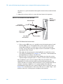
Figure 107 Agilent 10702A Linear Interferometer — dimensions
Laser and Optics User’s Manual, Vol. II
407
18 Agilent 10702A and 10766A Linear Interferometers, and Agilent 10703A and 10767 Retroreflectors
Agilent 10702A-001 Linear Interferometer with Windows
Specifications
Dimensions: see figure below
Weight: 246 grams (8.7 ounces)
Materials Used:
Housing: Stainless Steel (416)
Apertures: Plastic (Nylon)
Optics: Optical Grade Glass
Adhesives: Low Volatility (Vacuum Grade)
Maximum Angular Beam Deviation: ± 30 arc-seconds
Optical Efficiency (including Agilent 10703A Reflector):
Typical: 73%
Worst Case: 69%
Fundamental Optical Resolution: λ /2
Non-linearity Error: <4.2 nm (0.17 µin)
#4-40 Screws (2)
Beam
Spacing
12.7 mm
(0.50)
10703A
Centerline
28.5 mm
(1.12 Dia)
6-32 UNC (4 Places)
Thru Clearance
For #4 or (2.5 mm)
LIN
E
62.0 mm
(2.44)
38.2 mm
(1.50)
20.83 mm
Aperture
(0.82 Dia)
A
R
IN
Centerline
38.2 mm
(1.50)
32.0 mm
(1.26) Typ
33.3 mm
(1.31)
4 Sides
#4-40 x .25 Inch Deep
8 Places
Figure 108 Agilent 10702A-001 Linear Interferometer with Windows — dimensions
408
Laser and Optics User’s Manual, Vol. II
Agilent 10702A and 10766A Linear Interferometers, and Agilent 10703A and 10767 Retroreflectors
18
Agilent 10703A Retroreflector Specifications
Dimensions: see figure below
Weight: 41.5 grams (1.5 ounces)
Materials Used:
Housing: Stainless Steel (416)
Optics: Optical Grade Glass
Adhesives: Low Volatility (Vacuum Grade)
20.3 mm Aperture
(0.80 Dia)
37.6 mm
(1.48 Dia)
3.0 mm
(0.12)
28.5 mm
(1.12 Dia)
2.5 mm
(0.10)
33.3 mm
(1.31)
Bolt Circle
23.9 mm
(0.94)
Figure 109 Agilent 10703A Retroreflector — dimensions
Agilent 10713B 1-Inch Cube Corner Specifications
Dimensions: See drawings below.
Weight: 11.4 grams (0.4 ounces)
Nodal Point Depth: 12.57 mm (0.495 inch)
+ 0.00
mm
- 0. 25
+ .000
(1.000
Dia)
- .010
25.40
22.86 mm
(0.900 Dia min.
Clear Aperture)
+ 0.00
19.1 - 0. 76 mm
+ .000
(.750 - .0 30 )
Figure 110 Agilent 10713B 1-Inch Cube Corner, no housing — dimensions
Laser and Optics User’s Manual, Vol. II
409
18 Agilent 10702A and 10766A Linear Interferometers, and Agilent 10703A and 10767 Retroreflectors
Agilent 10766A Linear Interferometer Specifications
Dimensions: see figure below
Weight: 312 grams (11 ounces)
Materials Used:
Housing: Stainless Steel (416)
Apertures: Plastic (Nylon)
Optics: Optical Grade Glass
Adhesives: Low Volatility (Vacuum Grade)
Optical Efficiency (interferometer combination plus
remote Agilent 10767A Retroreflector):
Typical: 73%
Worst Case: 69%
A
R
ERFERO
INT
M
ER
30.0 mm
(1.18)
ET
40.0 mm
(1.57)
LIN
E
M3×0.5
24 Places
10766A
30.0 mm
(1.18)
65.0 mm
(2.56)
Note
Dotted outline shows possible Agilent 10767A
retroreflector mounting positions.
Figure 111 Agilent 10766A Linear Interferometer — dimensions
410
Laser and Optics User’s Manual, Vol. II
Agilent 10702A and 10766A Linear Interferometers, and Agilent 10703A and 10767 Retroreflectors
18
Agilent 10767A Retroreflector Specifications
Dimensions: see figure below
Weight: 224 grams (7.9 ounces)
Materials Used:
Housing: Stainless Steel (416)
Apertures: Plastic (Nylon)
Optics: Optical Grade Glass
Adhesives: Low Volatility (Vacuum Grade)
Captive Screw
2 Places
40.0 mm
(1.57)
25.0 mm
(0.98)
M3×0.5
4 Places
40.0 mm
(1.57)
20.0 mm Aperture
(0.79 Dia)
30.0 mm
(1.18)
30.0 mm
(1.18)
Figure 112 Agilent 10767A Linear Retroreflector — dimensions
Laser and Optics User’s Manual, Vol. II
411
18 Agilent 10702A and 10766A Linear Interferometers, and Agilent 10703A and 10767 Retroreflectors
412
Laser and Optics User’s Manual, Vol. II
Agilent Laser and Optics
User’s Manual Volume II
19
Agilent 10705A Single Beam
Interferometer and Agilent 10704A
Retroreflector
Description, 414
Special Considerations, 417
Mounting, 417
Installation, 418
Specifications and Characteristics, 419
Agilent Technologies
413
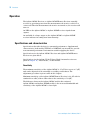
19 Agilent 10705A Single Beam Interferometer and Agilent 10704A Retroreflector
Description
The Agilent 10705A Single Beam Interferometer (see Figure 113) is intended
for use in low-mass or limited-space applications. This Interferometer is
designed for use with the Agilent 10704A Retroreflector (see Figure 113).
The single beam interferometer is called that because the outgoing and
returning beams are superimposed on each other, giving the appearance of
only one beam traveling between the interferometer and the retroreflector.
Functionally, this interferometer operates like a linear interferometer, but is
preferred when space for optics and beam paths is limited.
M IN
BEA TER
F
E
10
EF
R
L E CTO
6A
S/N
R
T
RE
O
R
R
ETE
M
O
R
SINGLE
The Agilent 10704A Retroreflector is a cube corner, but is considerably smaller
and lighter than the Agilent 10703A Retroreflector.
4A
70
70
5A
Agilent 10705A
Single Beam Interferometer
10
Agilent 10704A
Retroreflector
Figure 113 Agilent 10705A Single Beam Interferometer and Agilent 10704A Retroreflector
414
Laser and Optics User’s Manual, Vol. II
Agilent 10705A Single Beam Interferometer and Agilent 10704A Retroreflector
19
When using a single-beam interferometer, the receiver is usually mounted
perpendicular to the measurement beam, and the interferometer held
stationary. An optical schematic diagram of this interferometer is shown in
Figure 114.
REFERENCE and MEASUREMENT
PATHS (fA and fB )
Reference
Cube-corner
Agilent 10705A
Single Beam Interferometer
Quarter-wave
Plates
fB
Agilent 10704A
Retroreflector
fA
fA± Δf
fB
fA
From
Laser Head
fB
fA ± Δ f
To Receiver
LEGEND
= fA
=
= fB
= fA and fB
Rounded corners are used to help you trace paths.
Figure 114 Single Beam Interferometer — laser beam path
Laser beam path
A polarizing beam-splitter reflects fB to the reference cube corner and
transmits fA to the Agilent 10704A Retroreflector (Figure 114). The return
path is superimposes on the outgoing path. Since both beams leaving the
beam-splitter pass through a quarter-wave plate, the returning polarizations
are rotated through 90°. This causes fB to be transmitted and fA ±Δf to be
reflected so that they are directed coaxially to the receiver along a path
perpendicular to the input beam. Rotating the interferometer 90° switches
which optical frequency is in the measurement path, and thus changes the
direction sense.
Laser and Optics User’s Manual, Vol. II
415
19 Agilent 10705A Single Beam Interferometer and Agilent 10704A Retroreflector
Differential measurements
A differential measurement is one in which both the reference beam and the
measurement beam travel to external reflectors outside the interferometer
housing. This allows measurement of the relative positions of the two external
mirrors, either or both of which may be moving. Viewed another way, this
allows measuring the motion of one reflector relative to a reference datum
elsewhere in the machine, external to the interferometer itself. This is unlike
the typical interferometer configuration because usually the reference beam
path length does not change; in differential configurations, it can.
Take care during design and layout of a differential measurement to avoid
introduction of alignment errors, thermal or mechanical instabilities, and
potential deadpath problems. Both reflectors (reference and measurement)
should be of the same type (cube corner or plane mirror); this minimizes
thermal drift problems with ambient temperature changes.
To use an Agilent 10705A Interferometer in a differential measurement
configuration, the reference cube corner can simply be detached from the
interferometer housing and attached to the reference surface of interest. This
is shown, using an Agilent 10702A Interferometer for the example, in
Figure 7A-7. Be aware that all installation and alignment requirements for the
measurement reflector now apply also to the reference reflector.
Plane mirror measurements
The special option C01-10705A interferometer is an Agilent 10705A
interferometer specially modified to allow its use with plane mirrors or highly
reflective surfaces. The C01-10705A modification removes one quarter-wave
plate, resulting in an optical configuration similar to that of the
Agilent 10706A Plane Mirror Interferometer (described in Chapter 20 of this
manual); this configuration requires one Agilent 10704A retroreflector. The
C01-10705A interferometer’s receiver signal is separated by an Agilent 10700A
or Agilent 10701A Beam Splitter.
Typical measurement mirror alignment requirements for the C01-10705A (as a
function of distance) are the same as those for the Agilent 10706A Plane
Mirror Interferometer. Agilent 10706A interferometer specifications are given
in Chapter 20 of this manual.
416
Laser and Optics User’s Manual, Vol. II
Agilent 10705A Single Beam Interferometer and Agilent 10704A Retroreflector
19
Special Considerations
Effect of optics on measurement direction sense
The orientation and configuration of the interferometer affects the
measurement direction sense. The direction sense depends on which
frequency is in the measurement path of the interferometer. For example, if f1
(lower frequency) is in the measurement path and f2 (higher frequency) is in
the reference path and the optics are moving away from each other, the fringe
counts will be INCREASING. Interchanging f1 and f2 (perhaps by rotating the
interferometer 90°, the measurement direction sense will change. This
rotation causes switching of frequencies in the measurement path.
Configuration effects
The Agilent 10705A interferometer can be configured to turn the beam at right
angles. Be aware that doing this will cause the measurement direction sense to
be changed because the measurement reference paths are exchanged.
Mounting
Adjustable mounts
Agilent 10710B Adjustable Mount provides a convenient means of mounting,
aligning, and securely locking in position, the Agilent 10705A interferometer.
Since the mount allows some tilt and yaw adjustment, the need for custom
fixturing is minimized. This mount allows the optic mounted on it to be
rotated about its optical centerline, simplifying installation.
Chapter 4, “System Installation and Alignment,” in this manual shows how to
install an optic in various orientations, using an adjustable mount.
Fasteners
The Agilent 10705A interferometer is designed to be used with an
Agilent 10710B Adjustable Mount, and is supplied with English mounting
hardware.
Laser and Optics User’s Manual, Vol. II
417
19 Agilent 10705A Single Beam Interferometer and Agilent 10704A Retroreflector
Adapter plate
The Agilent 10705A-080 Adapter Plate adds an easy mounting surface to the
interferometer for mounting the remote lens assemblies of the Agilent 10780F,
Agilent E1708A, and Agilent E1709A remote receivers directly to the
interferometer.
Installation
Pre-installation checklist
In addition to reading chapters 2 through 4, and Chapter 12, “Accuracy and
Repeatability,” (in Volume I of this manual), complete the following items
before installing a laser positioning system into any application.
Complete Beam Path Loss Calculation (see Calculation of signal loss” in
Chapter 3, “System Design Considerations,” in Volume I of this manual).
Determine the direction sense for each axis, based on the orientation of the
laser head, beam-directing optic, and interferometer. Enter the direction
sense for each axis into the measurement system electronics. (See
Chapter 16, “Laser Heads,” Chapter 11, “Principles of Operation,” and
Chapter 12, “Accuracy and Repeatability,” in Volume I of this manual.
Provide for aligning the optics, laser head, and receiver(s) on the machine.
(Ideally, you want to be able to translate beam in two directions and rotate
beam in two directions for each interferometer input. This typically takes
two adjustment optics with proper orientations.)
Be sure to allow for transmitted beam offset of beam splitters
(Agilent 10700A and Agilent 10701A) in your design. (See the offset
specifications under the “Specifications” heading at the end of this
chapter.)
Refer to Chapter 4, “System Installation and Alignment,” in Volume I of this
manual for installation instructions.
Alignment
Alignment aids
Alignment aids for these interferometers are listed in Chapter 4, “System
Installation and Alignment,” in Volume I and Chapter 36, “Accessories,” of this
manual.
418
Laser and Optics User’s Manual, Vol. II
Agilent 10705A Single Beam Interferometer and Agilent 10704A Retroreflector
19
Procedure
Refer to Chapter 4, “System Installation and Alignment,” in Volume I of this
manual for alignment instructions.
Specifications and Characteristics
Specifications describe the device’s warranted performance. Supplemental
characteristics (indicated by TYPICAL or NOMINAL) are intended to provide
non-warranted performance information useful in applying the device.
The basic optical resolution using a linear interferometer is one half
wavelength (0.316 micron, 12.26 microinches).
Using electronic resolution extension, the system resolution is increased
significantly. Depending on the system, an additional resolution extension
factor of 32 (for Agilent 10885A and 10895A) or 256 (for Agilent 10897C and
10898A) is usually available.
Interferometer
Fundamental Optical
Resolution
System Resolution 1
(see NOTE)
System Resolution 2
(see NOTE)
Agilent 10705A
λ /2 (316.5 nm, 12.5 µin)
λ /64 (10.0 nm, 0.4 µin)
λ /512 (1.2 nm, 0.047 µin)
N O TE
The system resolution 1 is based on using 32X electronic resolution
extension. This is available with the Agilent 10885A and Agilent 10895A
electronics.
The system resolution 2 is based on using 256X electronic resolution
extension. This is available with the Agilent 10897C and Agilent 10898A
electronics.
Laser and Optics User’s Manual, Vol. II
419
19 Agilent 10705A Single Beam Interferometer and Agilent 10704A Retroreflector
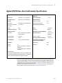
Agilent 10705A Single Beam Interferometer Specifications
Dimensions: see figure below
Weight: 85.5 grams (3.0 ounces)
Materials Used:
Housing: Stainless Steel (416)
Apertures: Plastic (Nylon)
Optics: Optical Grade Glass
Adhesives: Low Volatility (Vacuum Grade)
Maximum Angular Beam Deviation: ± 30 arc-minutes
Optical Efficiency (including Agilent 10703A Reflector):
Typical: 62%
Worst Case: 59%
Fundamental Optical Resolution: λ /2
Non-linearity Error: <4.2 nm (0.17 µin)
Thermal Drift Coefficient:
0.05 micron/°C, typical
0.005 micron/°C, minimum
0.110 micron/°C, maximum
#2-56 Screws (2)
Centerline
15.2 mm
(0.60 Dia)
6-32 UNC (4 Places)
Thru Clearance
For #4 or (2.5 mm )
39.88 mm
(1.57)
SINGL
E
BE
25.65 mm
(1.01)
8.9 mm
Aperture
(0.35 Dia)
25.65
5.65 mm
(1.01)
Centerline
#2-56
4 Places
19.56 mm
(
(0.77)
Typ
19.56 mm
(0.77)
19.56 mm
(0.77)
Figure 115 Agilent 10705A Single Beam Interferometer — dimensions
420
Laser and Optics User’s Manual, Vol. II
Agilent 10705A Single Beam Interferometer and Agilent 10704A Retroreflector
19
Agilent 10704A Retroreflector Specifications
Dimensions: see figure below
Weight: 10.5 grams (0.37 ounce)
Materials Used:
Housing: Stainless Steel (416)
Optics: Optical Grade Glass
Adhesives: Low Volatility (Vacuum Grade)
10.2 mm
Aperture
(0.40 Dia)
19.5 mm
(0.77)
Bolt Circle
20.5 mm
(0.81 Dia)
2.5 mm
(0.10)
15.2 mm
(0.60 Dia)
2.5 mm
(0.10)
14.3 mm
(0.56)
Figure 116 Agilent 10704A Retroreflector — dimensions
Agilent 10713C 1/2-Inch Cube Corner Specifications
Dimensions: see figure below
Weight: 1.4 grams (0.05 ounce)
Nodal Point Depth: 6.33 mm (0.248 inch)
+ 0.25
- 0.00
+ 0.010
(0.500
- 0.000
12.70
mm
Dia)
11.43 mm
(0.450 Dia min.
Clear Aperture)
+ 0.00
9.53 - 0.51 mm
+ 0.000
(0.375 - 0.020 )
Figure 117 Agilent 10713C 1/2-Inch Cube Corner, no housing — dimensions
Laser and Optics User’s Manual, Vol. II
421
19 Agilent 10705A Single Beam Interferometer and Agilent 10704A Retroreflector
Agilent 10713D 1/4-Inch Cube Corner Specifications
Dimensions: see figure below
Weight: 0.2 grams (0.007 ounce)
Nodal Point Depth: 3.14 mm (0.123 inch)
Angular Deviation: 2 inches (arc second)
6.35 ± 0.2 mm Dia.
(0.250 ± 0.008 in Dia.)
5.71 mm
(0.225 Dia min.
Clear Aperture)
4.75 ± 0.25 mm
(0.187 ± 0.010)
Figure 118 Agilent 10713D Cube Corner, no housing — dimensions
422
Laser and Optics User’s Manual, Vol. II
Agilent Laser and Optics
User’s Manual Volume II
20
Agilent 10706A Plane Mirror
Interferometer
Description, 424
Special Considerations, 428
Mounting, 430
Installation, 431
Alignment, 432
Specifications and Characteristics, 438
Converting to High-Stability Plane Mirror Interferometer, 442
Agilent Technologies
423
20 Agilent 10706A Plane Mirror Interferometer
Description
This chapter describes:
• the Agilent 10706A Plane Mirror Interferometer
• the Agilent 10723A High Stability Adapter
The Agilent 10706A Plane Mirror Interferometer can be used with a plane
mirror reflector to obtain distinct advantages.
The unique contribution of the Agilent 10706A Plane Mirror Interferometer
(see Figure 119) is its tolerance of angular misalignment of the plane mirror
reflector. A simple linear interferometer would require a plane mirror to
remain perpendicular to the laser beam within several arc-seconds; otherwise,
the interference fringes would not be detectable. With the Agilent 10706A
interferometer, angular deviations of minutes of arc are commonly acceptable.
With this measurement optic, interference fringes are detectable even though
the measurement beam is not at perfect right angles to the mirror. Therefore,
several valuable applications become possible. For example, in a two-axis laser
measurement system, the X reflector can be allowed to move in the Y direction
without affecting the signal strength or the X measurement. Consequently,
both reflectors of a two-axis system can be mounted on the same moving part
to minimize Abbé offset error. Defining the measuring point as the point where
the two axis beams cross, the measurement is essentially independent of yaw
of the moving stage. Such a design is shown in Figure 120.
Compare the system shown in Figure 120 to a two-axis system using linear or
single-beam interferometers. The X-axis retroreflector must be mounted on a
part of the stage that moves in the X direction and not in the Y direction. Also,
the Y-axis retroreflector must be mounted on a different part of the stage that
is allowed to move in the Y direction and not in the X direction. These
constraints prevent two-axis measurements from being made on the same part
of the stage. Further, there will be some geometry error in the system if it is
not perfectly rigid.
The Agilent 10706A Plane Mirror Interferometer uses a flat mirror reflector.
For X-Y stage applications, the user must provide the mirror(s). For single-axis
applications, the Agilent 10724A Plane Mirror Reflector may be used. This
device is described more fully in Chapter 36, “Accessories,” of this manual.
424
Laser and Optics User’s Manual, Vol. II
Agilent 10706A Plane Mirror Interferometer
20
06A PLA
IRR
NE M OR IN
T
ETER
ROM
107
FE
R
E
107
06A
Agilent 10706A
Plane Mirror Interferometer
Figure 119 Agilent 10706A Plane Mirror Interferometer
Work Surface Plane
MO X-Y
TIO
N
90˚
Laser Beam
Laser Beam
Plane Mirror
Interferometer
N
TIO
MO
ED
FIX
X-Axis
Receiver
Agilent 5517C
Laser Head
Plane Mirrors
Plane Mirror
Interferometer
Y-Axis
Receiver
Beam Splitter
Figure 120 X-Y Stage measurement with Agilent 10706A Plane Mirror Interferometer
Laser and Optics User’s Manual, Vol. II
425
20 Agilent 10706A Plane Mirror Interferometer
In an Agilent 10706A interferometer, the measurement beam travels twice
between the interferometer and the plane mirror, thus the resolution of the
measurement is twice that of the linear or single beam interferometers. With
32X electronic resolution extension, this results in a resolution of λ /128 (5
nanometers or 0.2 microinch) with the plane mirror interferometer, compared
to λ /64 (10 nanometers or 0.4 microinch) with the linear or single beam
interferometers.
The Agilent 10706A interferometer can be converted to the Agilent 10706B
high-stability interferometer configuration by retrofitting the Agilent 10706A
with an Agilent 10723A High Stability Adapter. Information for the conversion
is contained later in this chapter. The Agilent 10706B interferometer is
described in Chapter 21 of this manual.
Laser beam paths
For purposes of this discussion, the laser beam input is through the
interferometer's Aperture B, and the output to the receiver is through
Aperture A (see Figure 121).
After entering Aperture B, the beam from the laser head is split at the surface
of a polarizing beam-splitter.
One frequency (fB) enters the interferometer's reference path, which directs it
to the reference cube corner and then out to the receiver.
The second frequency (fA) enters the interferometer's measurement path. This
beam is transmitted out to the plane mirror reflector and is reflected back on
itself (Figure 121). The interferometer's quarter-wave plate causes the
polarization of the return frequency to be rotated through 90° so that fA ± Δf is
reflected out a second time where it is Doppler shifted again. The polarization
of fA ± 2Δf is rotated again through 90° so it is now transmitted back to the
receiver. Resolution doubling is inherent because of the double Doppler shift.
426
Laser and Optics User’s Manual, Vol. II
Agilent 10706A Plane Mirror Interferometer
MEASUREMENT PATH (fA)
Quarter-wave
Plate
fA± Δ f
fA
Aperture B
fA
fA ± 2 Δ f
fA± 2 Δ f
Aperture A
20
fA± Δ f
fA± Δ f
Plane
Reflector
Agilent 10706A
Plane Mirror Interferometer
REFERENCE PATH (fB)
Quarter-wave
Plate
fB
Aperture B
fB
Aperture A
Plane
Refelector
Agilent 10706A
Plane Mirror Interferometer
COMPOSITE (fA and fB)
Quarter-wave
Plate
fB
fA
fA± Δ f
fB
fA
Aperture B
Aperture A
fA± 2 Δ f
fA± 2 Δ f
fB
fA± Δ f
fA± Δ f
Agilent 10706A
Plane Mirror Interferometer
Plane
Refelctor
LEGEND
= fA
=
= fB
= fA and fB
Rounded corners are used to help you trace paths.
Figure 121 Plane mirror interferometer laser beam path
Laser and Optics User’s Manual, Vol. II
427
20 Agilent 10706A Plane Mirror Interferometer
Special Considerations
Differential measurements
A general discussion of differential measurements using laser interferometers
is given in the introduction to this section.
To use the Agilent 10706A interferometer in a differential configuration: 1)
replace the reference cube Corner (or high-stability adapter) with the Agilent
10722A Plane Mirror Converter, and 2) attach the reference plane mirror to
the reference surface of interest. This is shown in Figure 122. Be sure to install
and align the reference reflector the same as you would the measurement
reflector.
Turned configuration
To reduce the number of beam benders for this application, the interferometer
can be configured to turn the beam. This is done by interchanging the
reference cube corner and the plane mirror converter. Figure 123 shows a
reconfigured Plane Mirror Interferometer that turns the beam. Note the
location of the plane mirror converter with respect to the arrows on the label.
In this configuration (Figure 123), the laser measurement beam is turned to
the left. When the measurement beam needs to be turned to the right (as
Figure 123, X-axis), the interferometer is rotated 180° about the incoming
beam’s optical axis.
N O TE
428
With this change in configuration, the measurement direction sense will
change (see the “Effect of optics on measurement direction sense”
section in Chapter 3, “System Design Considerations,“ in Volume I of this
manual).
Laser and Optics User’s Manual, Vol. II
Agilent 10706A Plane Mirror Interferometer
20
REFERENCE and MEASUREMENT
PATHS (fA and fB)
fB±ΔfB
fB
fB±2ΔfB
fB±ΔfB
Quarter-wave
Plate
Agilent 10722A
Plane Mirror Converter
fA
fA±ΔfA
fB
fA±2ΔfA
Reference
Plane Mirror
Reflector
fA±2ΔfA
fB±2ΔfB
Agilent 10706A
Plane Mirror Interferometer
fA
fA±ΔfA
Measurement
Plane Mirror
Reflector
LEGEND
= fA
=
= fB
= fA and fB
Rounded corners are used to help you trace paths.
Figure 122 Differential measurements with the Agilent 10706A
Agilent 10706A
Plane Mirror Interferometer
Reference Cube-corner
(New Location)
10706A
METER
ERO
RF
E
ROR IN
MIR
TE
Plane Mirror
Converter
10706A PLAN
Turned Configuration
Figure 123 Differential measurements with the Agilent 10706A
Laser and Optics User’s Manual, Vol. II
429
20 Agilent 10706A Plane Mirror Interferometer
X-Y STAGE
X A xis
Plane Mirror
Interferometer
X
Y
X A xis
Receiver
MIRRORS
X A xis
Laser Beam
Alignment A id
(P/N 10706-60001)
Laser
Y A xis
Laser Beam
Y A xis
Plane Mirror
Interferometer
50%
Beam
Splitter
Y A xis
Receiver
Alignment T arget
(P/N 10702-60001)
Test
Point
Voltmeter
Figure 124 Agilent 10706A Plane Mirror Interferometer—alignment
Mounting
Adjustable mounts
The Agilent 10711A Adjustable Mount provides a convenient means of
mounting, aligning, and securely locking the Agilent 10706A interferometer in
position. Since the mount allows some tilt and yaw adjustment, the need for
custom fixturing is minimized. The mount allows the interferometer to be
rotated about its centerline, simplifying installation.
Fasteners
The Agilent 10706A interferometer is supplied with English mounting
hardware, which is required to fasten it to its adjustable mount.
430
Laser and Optics User’s Manual, Vol. II
Agilent 10706A Plane Mirror Interferometer
20
Adapter plate
The Agilent 10706A-080 Adapter Plate adds an easy mounting surface to the
interferometer for mounting the remote lens assemblies of the Agilent 10780F,
Agilent E1708A, and Agilent E1709A remote receivers directly to the
interferometer.
Installation
Pre-installation check
In addition to reading chapters 2 through 4, and Chapter 12, “Accuracy and
Repeatability,” (in Volume I of this manual), complete the following items
before installing a laser positioning system into any application.
Complete Beam Path Loss Calculation (see Calculation of signal loss” in
Chapter 3, “System Design Considerations,” in Volume I of this manual).
You must supply the plane mirror reflectors if the Agilent 10724A Plane
Mirror Reflector will not work for your installation. See Chapter 12,
“Accuracy and Repeatability,” Chapter 17, “Beam-Directing Optics,” or
Chapter 5, “Measurement Optics (General Information),” in Volume I of this
manual for mirror specifications.
Determine the direction sense for each axis, based on the orientation of the
laser head, beam-directing optic, and interferometer. Enter the direction
sense for each axis into the measurement system electronics. (See
Chapter 16, “Laser Heads,” Chapter 11, “Principles of Operation”, and
Chapter 12, “Accuracy and Repeatability,” in Volume I of this manual.
Provide for aligning the optics, laser head, and receiver(s) on the machine.
(Ideally, you want to be able to translate beam in two directions and rotate
beam in two directions for each interferometer input. This typically takes
two adjustment optics with proper orientations.)
Be sure to allow for transmitted beam offset of beam splitters
(Agilent 10700A and Agilent 10701A) in your design. (See the offset
specifications under the “Specifications” heading at the end of this
chapter.)
Laser and Optics User’s Manual, Vol. II
431
20 Agilent 10706A Plane Mirror Interferometer
Alignment
General
This procedure covers specifically the alignment of the Agilent 10706A Plane
Mirror Interferometer as applied to an X-Y positioning system using flat
mirrors as measurement reflectors.
It is assumed that:
1 the mirror surfaces are flat to within the tolerances required for operation
of the plane mirror interferometer. (Refer to the recommendations under
the “Specifications” heading at the end of this chapter), and
2 the mirror surfaces have been aligned perpendicular to each other and their
respective directions of travel.
Figure 124 illustrates the most common 2-axis plane mirror interferometer
installation. The interferometers have been configured to turn the beam in this
example.
The alignment of the plane mirror interferometer uses the autoreflection
alignment technique described in Chapter 4, “System Installation and
Alignment,” in Volume I of this manual. In most cases, the accuracy demands
of the X-Y positioning devices used, along with the relatively short travels
encountered, dictate that the high accuracy alignment technique described in
the autoreflection alignment procedure be used.
The alignment procedure follows the instructions for using the alignment aids,
which begin below.
Alignment aids
Figure 125 shows the two alignment aids supplied with the Agilent 10706A
Plane Mirror Interferometer:
• Alignment Target, Agilent Part Number 10702-60001
• Alignment Aid, Agilent Part Number 10706-60001
Both aids are magnetic to simplify positioning on the interferometer.
432
Laser and Optics User’s Manual, Vol. II
Agilent 10706A Plane Mirror Interferometer
20
GET
REMOVE TAR
ING
AFTER ALIGN
logies
Agilent Techno
echnolo
Agilent T
gies
Alignment Target
P/N 10702-60001
Alignment Aid
P/N 10706-60001
Figure 125 Agilent 10706A Interferometer — alignment aids
The Alignment Target (Agilent Part Number 10702-60001) is used on the input
side of the interferometer to properly position the beam in the aperture.
The Alignment Aid (Agilent Part Number 10706-60001) is placed on the output
aperture of the interferometer to allow autoreflection. This aid contains a
quarter-wave plate to reflect the measurement beam back on itself and return
it to the laser head without offset.
The Alignment Aid must be positioned to transmit the primary measurement
beam. This is the first of the two measurement beams that travel between the
Agilent 10706A interferometer and the plane mirror reflector. To identify the
primary beam, block one of the two measurement beams; if the other beam
also disappears, the beam you blocked is the primary measurement beam.
Laser and Optics User’s Manual, Vol. II
433
20 Agilent 10706A Plane Mirror Interferometer
Alignment procedure
This procedure describes the alignment of Agilent 10706A Plane Mirror
Interferometers used on an X-Y stage application. (See Figure 124)
N O TE
Steps 1 through 11 constitute the Y-axis alignment.
1 Place the interferometer alignment target on the laser side of the Y-axis
plane mirror interferometer and place the receiver alignment target on the
receiver (Figure 126, position 1). Place a piece of opaque material such as
translucent tape between the Y-axis plane mirror interferometer and the
mirror.
2 Adjust the laser head until the laser beam 1) passes through the 50% beam
splitter, 2) enters one hole of the interferometer alignment target, and 3)
exits the other hole centered on the receiver alignment target. Fasten the
laser head securely.
3 Select the small aperture of the laser head and install the alignment aid on
the output of the plane mirror interferometer in the correct orientation (the
hole transmits the first pass of the measurement beam to the measurement
mirror). Remove the opaque material from between the plane mirror
interferometer and the mirror.
ALIGNMENT TARGET FOR RECEIVER
Laser Beam
Receiver Alignment
Target Position 2
Receiver Alignment
Target Position 1
To Interferometer
Receiver
From Interferometer
Figure 126 Receiver and receiver alignment target
434
Laser and Optics User’s Manual, Vol. II
Agilent 10706A Plane Mirror Interferometer
20
4 The laser beam will now exit the interferometer and be reflected by the
mirror back upon itself into the interferometer. Pitch and yaw the plane
mirror interferometer until the beam reflected from the mirror returns
upon itself through the plane mirror interferometer and back to the small
aperture of the laser head. Slight lateral translations of the plane mirror
interferometer may be required to ensure that the reference beam is still
centered on the receiver alignment target. If the distance between the
mirror and the laser head is at least 0.5 meter (20 inches), the formula
below determines the cosine error based on the offset of the return beam at
the laser head.
2
S
E = ---------2
8D
where:
E is the cosine error value
S is the offset of the returning beam (in micrometers or microinches)
D is the measured (displacement) distance (in millimeters or inches)
For example, if the distance measured is 600 mm and it results in a 1.2-mm
(1200-micrometer) offset, cosine error (E) will be:
2
( 1200 )
E = --------------------------------- = 0.5ppm ( 0.5 micrometer per meter of travel )
2
( 8 ) × ( 600 )
N O TE
For high accuracy alignment or for installations where there is less than
0.5 meter (20 inches) between the laser and mirror, perform steps 5
through 7.
5 Remove the receiver target and plane mirror interferometer alignment
target and select the large aperture of the laser head. Do not remove the
plane mirror interferometer alignment aid on the output side of the plane
side of the plane mirror interferometer.
6 With a fast-responding voltmeter (preferably an analog type) attached to
the receiver test point, pitch and yaw the plane mirror interferometer until
a signal is received on the receiver. (The voltmeter will suddenly jump to
some value greater than 0. 25 volt.) This is a critical adjustment and may
initially require great care.
7 Adjust the plane mirror interferometer in pitch and yaw until the voltmeter
reading (which may be fluctuating) is maximum. Now carefully readjust the
interferometer until the voltage reading suddenly drops back down to about
0.3 volt.
Laser and Optics User’s Manual, Vol. II
435
20 Agilent 10706A Plane Mirror Interferometer
N O TE
The alignment should be adjusted such that the voltage reading from the
receiver test point occurs just below the sudden jump up in voltage. If the
alignment is fixed to sustain this peaked voltage, system operation will be
degraded.
This aligns the laser beam to within ±1.2 arc-minutes to the direction of travel,
resulting in a cosine error of approximately 0.05 ppm. That is 0.05 micron per
meter of travel (0.05 microinch per inch) of cosine error.
8 Fasten the plane mirror interferometer (Y-axis) securely, preserving the
alignment.
9 Monitor the voltage reading along the complete travel of the stage (Y-axis).
The voltage should not jump up to the previous maximum voltage reading.
If the voltage does jump, readjust the interferometer until the voltage
reading suddenly drops back down to about 0.3 volt.
10 Remove the plane mirror interferometer alignment target and alignment
aid. The reference beam and the measurement beam must be centered on
the receiver alignment target.
11 Remove the receiver alignment aids and rotate the turret on the laser head
to the large aperture. Verify that the LED indicator on the receiver is lighted
and the voltage at the receiver test point is between 0.6 and 1.3 Vdc.
N O TE
Steps 12 through 20 constitute the X-axis alignment.
12 With the laser head turret in the large aperture position, place the plane
mirror interferometer alignment target on the laser head side of the X-axis
plane mirror interferometer and the receiver alignment target on the
receiver (Figure 126, position 1). Place a piece of opaque material between
the X-axis plane mirror interferometer and the mirror.
13 Pitch and yaw the 50% beam splitter until the laser beam enters one hole of
the plane mirror interferometer alignment target and exits the other,
centered on the receiver alignment target (do not adjust the laser head).
Slight lateral translations of the 50% beam splitter may be necessary to
ensure there is no beam clipping. Fasten the 50% beam splitter securely.
14 Select the small aperture on the front turret of the laser head and install the
alignment aid on the output of the plane mirror interferometer in the
correct orientation (the hole transmits the first pass of the measurement
beam to the measurement mirror). Remove the opaque material from
between the plane mirror interferometer and the mirror.
15 The laser beam now exits the interferometer and is reflected by the mirror
back upon itself and into the interferometer. Pitch and yaw the plane
mirror interferometer until the beam reflected from the mirror returns
436
Laser and Optics User’s Manual, Vol. II
20
Agilent 10706A Plane Mirror Interferometer
through the plane mirror interferometer and back to the small aperture of
the laser head. Slight lateral translations of the plane mirror interferometer
may be required to ensure that the reference beam is still centered on the
receiver alignment target. If the distance between the mirror and the laser
head is at least 0.5 meter (20 inches), the formula given earlier in this
alignment procedure will determine the cosine error based on the offset of
the return beam at the laser.
N O TE
For high accuracy alignment or for installation where there is less than 0.
5 meter (20 inches) between the laser and mirror, perform steps 16
through 18.
16 Remove the receiver alignment target and plane mirror interferometer
alignment target and select the large aperture of the laser head. Do not
remove the plane mirror interferometer alignment aid on the output side of
the plane mirror interferometer.
17 With a fast-responding voltmeter attached to the receiver's test point, pitch
and yaw the plane mirror interferometer until a signal is received on the
receiver. (The voltmeter will suddenly jump to some value greater than
0.25 volt.) This is a critical adjustment and may initially require great care
to achieve the desired result.
18 Adjust the plane mirror interferometer in pitch and yaw until the voltmeter
reading (which may be fluctuating) is maximum. Now carefully readjust the
interferometer until the voltage reading suddenly drops back down to about
0.3 volt.
N O TE
The alignment should be adjusted such that the voltage reading from the
receiver test point occurs just below the sudden jump up in voltage. If the
alignment is fixed to sustain this peaked voltage, system operation will be
degraded.
This aligns the laser beam to within ±1.2 arc-minutes to the direction of travel,
resulting in a cosine error of approximately 0.05 ppm. That is 0.05 micron per
meter of travel (0.05 microinch per inch) of cosine error.
19 Fasten the plane mirror interferometer (X-axis) securely, preserving the
alignment.
20 Monitor the voltage reading along the complete travel of the stage (x-axis).
The voltage should not jump up to the previously peaked voltage reading. If
the voltage does jump, readjust the interferometer until the voltage reading
suddenly drops down to about 0.3 volt.
21 Remove the plane mirror interferometer alignment target and alignment
aid. The reference beam and the measurement beam must be centered on
the receiver alignment target.
Laser and Optics User’s Manual, Vol. II
437
20 Agilent 10706A Plane Mirror Interferometer
22 Remove the receiver alignment aids and rotate the turret on the laser head
to the large aperture. Verify the LED indicator on the receiver is lighted and
the voltage at the receiver test point is between 0.6 and 1.3 Vdc.
Specifications and Characteristics
Specifications describe the device’s warranted performance. Supplemental
characteristics (indicated by TYPICAL or NOMINAL) are intended to provide
non-warranted performance information useful in applying the device.
Plane mirror systems have a basic optical resolution of one quarter wavelength
(0. 158 micron, 6.23 microinches).
Using electronic resolution extension, the system resolution is increased
significantly. Depending on the system, an additional resolution extension
factor of 32 (for Agilent 10885A and 10895A) or 256 (for Agilent 10897C and
10898A) is usually available.
Interferometer
Fundamental Optical
Resolution
Agilent 10706A
λ /4 (158.2 nm, 6.2 µin)
N O TE
System Resolution 1
(see NOTE)
System Resolution 2
(see NOTE)
λ /128 (5.0 nm, 0.2 µin)
λ /1024 (0.62 nm, 0.024 µin)
The system resolution 1 is based on using 32X electronic resolution
extension. This is available with the Agilent 10885A and Agilent 10895A
electronics.
The system resolution 2 is based on using 256X electronic resolution
extension. This is available with the Agilent 10897C and Agilent 10898A
electronics.
438
Laser and Optics User’s Manual, Vol. II
20
Agilent 10706A Plane Mirror Interferometer
Agilent 10706A Plane Mirror Interferometer Specifications
Weight: 308 grams (10.9 ounces)
NOTE: Flatness deviations will appear as measurement errors
Dimensions: see figure below
when the mirror is translated across the beam. Mount should be
Materials Used: same as Agilent 10702A Interferometer
kinematic so as not to bend mirror. If accuracy requirements
Optical Efficiency: (including a 98% efficient plane mirror reflector):
demand it, mirror flatness might be calibrated (scanned and
stored in the system controller) to be used as a correction
Typical: 70%
factor.
Worst Case: 54%
Fundamental Optical Resolution: λ /4
Optical Surface Quality: 60 — 40 per MIL-0-13830
Non-linearity Error: <2.2 nm (0.09 µin)
MIRROR ALIGNMENT REQUIREMENTS VS DISTANCE:
PLANE MIRROR (MEASUREMENT MIRROR) SPECIFICATIONS
Reflectance: 98% for 633 nanometers at normal incidence
(minimum 80%)
Maximum Angular Misalignment: Depends on distance
between interferometer and plane mirror.
Typical values are:
Flatness: Depending on the application and accuracy requirements of
the application, mirror flatness may range from λ /4 to λ /20; i.e., 0.16
to 0.03 µmeters (6 to 1.2 µinches).
±6 arc-minutes for 152 mm (6 inches)
±3 arc-minutes for 305 mm (12 inches)
±1.5 arc-minutes for 508 mm (20 inches)
To Plane Mirror
From Laser
Beam Spacing
12.7 mm
(0.50)
To Receiver
28.5 mm
(1.12)
52.1 mm
(2.05)
14 mm
(0.55)
32 mm
(1.26)
38.1 mm
(1.50)
28.5 mm
(1.12)
85.9 mm
(3.38)
Aperture Dia
20.8 mm
(0.82)
33.3 mm
(1.31)
38.1 mm
(1.50)
32 mm
(1.26)
4x Drilled For Clearance
of 4-40 Screw and tapped
6-32 UNC-2B × .250 deep
4x this side and 4x far side.
Figure 127 Agilent 10706A Plane Mirror Interferometer — dimensions
Laser and Optics User’s Manual, Vol. II
439
20 Agilent 10706A Plane Mirror Interferometer
Agilent 10722A Plane Mirror Converter Specifications
Weight: 34.3 grams (1.2 ounces)
Dimensions: see figure below
Materials Used:
Housing: 416 Stainless Steel
Optics: Optical Grade Glass
Clear Aperture: 0.900 in
22.9 mm Thru
(0.90) Dia
28.5 mm
(1.12) Dia
37.6 mm
(1.48) Dia
3.0 mm
(0.12)
2 PLS
32.7 mm
(1.29)
Bolt Circle
2.5 mm
(0.10)
13.97 mm
(0.55)
Figure 128 Agilent 10722A Plane Mirror Converter — dimensions
Agilent 10723A High Stability Adapter Specifications
Weight: 48.8 grams (1.7 ounces)
For Specifications of an upgraded Agilent 10706A (replacement of
Dimensions: see drawings below
reference cube corner with Agilent 10723A), see Agilent 10706B
Materials Used:
Specifications (in Chapter 21 of this manual).
Housing: Stainless Steel
Cap: Plastic (Nylon)
Optics: Optical Grade Glass
Adhesives: Low Volatility (Vacuum Grade)
22.9 mm Thru
(0.90) Dia
5.6 mm
(0.10)
4 × 2-56 UNC-3B Thru
4 × 15°
32.7 mm
(1.29)
Bolt Circle
3.0 mm
(0.13)
37.6 mm
(1.48) Dia
2.0 mm
(0.08)
28.5 mm
(1.12) Dia
2.5 mm
(0.10)
23.9 mm
(0.94)
Figure 129 Agilent 10723A High Stability Adapter — dimensions
440
Laser and Optics User’s Manual, Vol. II
Agilent 10706A Plane Mirror Interferometer
20
Agilent 10724A Plane Mirror Reflector Specifications
Weight: 50 grams (1.8 ounces)
Flatness: λ /10 (at 633 nanometers)
Dimensions: see figure below
Installed Angular Adjustment Range: Pitch/Yaw 1° configurations
Materials Used: 416 Stainless Steel
Reflectivity: 98% at 633 nanometers at normal incidence
20.066 mm
(0.790)
2 ´ 3.556 mm Dia
(0.140)
3.810 mm
(0.150)
42.164 mm Dia
(1.660)
28.388 mm Dia
(1.118)
32.766 mm Dia
(1.290)
22.860 mm Dia
(0.900)
Thru
Aperture
36.068 mm Dia
(1.420)
3 ´ 2 -56 NC-Class 3 Thru
120˚ Apart
Figure 130 Agilent 10724A Plane Mirror Reflector — dimensions
Laser and Optics User’s Manual, Vol. II
441
20 Agilent 10706A Plane Mirror Interferometer
Converting to High-Stability Plane Mirror Interferometer
General
The Agilent 10706A Plane Mirror Interferometer can be converted to a version
having improved thermal stability equivalent to the Agilent 10706B High
Stability Plane Mirror Interferometer by replacing the REFERENCE cube
corner with an Agilent 10723A High Stability Adapter (see Figure 129).
Instructions for the conversion are given below.
To convert an Agilent 10706A Plane Mirror Interferometer to the
Agilent 10706B configuration
N O TE
The Agilent 10723A adapter MUST be installed in place of the
REFERENCE cube corner on the Agilent 10706A interferometer. If it is
inadvertently installed on the other side, the thermal stability will become
worse. Refer to Figure 131 for the proper installation orientation.
1 Refer to Figure 131 and positively identify the position in which to install
the Agilent 10723A adapter. Note that in either configuration, the Agilent
10723A adapter replaces the REFERENCE CUBE-CORNER (Agilent 10703A
Retroreflector).
2 Remove the REFERENCE CUBE-CORNER and store it in a safe place.
3 Refer to Figure 131. If the interferometer is in the straight-through
configuration, proceed to step 5 and install the Agilent 10723A adapter
using the mounting screws that were used to mount the Reference
Cube-Corner.
If the interferometer is in the turned configuration, use the new hardware
supplied with the Agilent 10723A adapter to mount the adapter as
described in step 4.
4 Using the hex key provided, install the four 2-56 × 3/16 inch long screws
into the holes on the flange of the Agilent 10723A adapter housing. Be sure
they do not protrude through the flange.
a Equip both 4-40 × 1/2 inch long mounting screws with a compression
spring and use them to install the Agilent 10723A adapter in place of the
removed Reference Cube-Corner. Either set of mounting slots may be
used to attached the High Stability Adapter to the interferometer.
442
Laser and Optics User’s Manual, Vol. II
Agilent 10706A Plane Mirror Interferometer
20
b Tighten both mounting screws until the head of each just begins to
compress the spring. Then tighten each screw two turns to properly
compress each spring.
c Continue to step 5.
H STABIL
10
I
R
ADAPTE
S/N
7
27 23A
20
MA
A
D
U. S E
.A. IN
TY
HIG
Agilent 10723A
High Stability Adapter
Figure 131 Agilent 10723A High Stability Adapter
Agilent 10706A
Plane Mirror Interferometer Conversion
Using the
Agilent 10723A
High Stability Adapter
Plane Mirror
Converter
Agilent 10723A
High Stability
Adapter
Agilent 10723A
High Stability
Adapter
Compression Springs
(for turned configuration only)
Plane Mirror
Converter
ER
A
E
E
ROR
MIR
1070
10706A
070
ROR IN
MIR
ET
ROM ER
0706A PLA
N
10706A PLA
N
Cube-Corner
Straight-through Configuration
Cube-Corner
Turned Configuration
Figure 132 Agilent 10706A Conversion Using the Agilent 10723A
Laser and Optics User’s Manual, Vol. II
443
20 Agilent 10706A Plane Mirror Interferometer
5 Install the Agilent 10723A High Stability Adapter in place of the removed
reference cube corner. Either set of mounting slots may be used to attach
the High Stability Adapter to the interferometer.
6 Refer to Figure 131. Locate and remove the PLANE MIRROR CONVERTER.
7 The black plastic bezel under the plane mirror converter must be removed
to allow access for an Alignment Aid during setup. The bezel is secured with
silicone adhesive, but can be easily removed. Place the blade of a small
screwdriver under the lip of the bezel and pry the bezel out. PRY THE
SCREWDRIVER AWAY FROM THE BEAM SPLITTER GLASS, TAKING CARE
THAT IT DOES TO COME IN CONTACT WITH OR SCRATCH THE OPTIC.
Discard the bezel.
8 Replace the plane mirror converter that was removed in step 4.
This completes the conversion. The converted interferometer must be
realigned as described in the alignment sections for the Agilent 10706B
High Stability Plane Mirror Interferometer in Chapter 21 of this manual.
444
Laser and Optics User’s Manual, Vol. II
Agilent Laser and Optics
User’s Manual Volume II
21
Agilent 10706B High Stability Plane
Mirror Interferometer
Description, 446
Special Considerations, 449
Mounting, 449
Installation, 449
Alignment, 449
Straight-Through Configuration, 450
Turned Configuration, 450
Specifications and Characteristics, 463
Agilent Technologies
445
21 Agilent 10706B High Stability Plane Mirror Interferometer
Description
The Agilent 10706B High Stability Plane Mirror Interferometer (see
Figure 133) is an improved version of the Agilent 10706A interferometer. It
offers very high thermal stability. Its thermal drift is typically 1/12 that of a
conventional plane mirror interferometer.
The Agilent 10706B High Stability Plane Mirror Interferometer uses plane
mirror reflectors. For X-Y stage applications, the user must provide the
mirror(s).
Using plane mirror reflectors allows for a marked improvement in
measurement stability, thereby reducing the designer's error budget. Existing
system designs can be easily upgraded, since the Agilent 10706B
interferometer is an exact functional replacement for the Agilent 10706A
interferometer, and is the same size and weight. It can be used in the same
applications as the Agilent 10706A interferometer, but requires different
alignment techniques. See the “Alignment” section later in this chapter for
alignment procedures.
Externally, and in its use, the Agilent 10706B interferometer is identical to the
Agilent 10706A Plane Mirror Interferometer described in the previous chapter
(Chapter 20). Internally, however, the design and configuration of the
Agilent 10706B interferometer’s optical elements differs from that of the
Agilent 10706A interferometer. You can see this difference by comparing the
laser path drawings for the two interferometers.
In addition to the material presented in this chapter, you should also read
about the Agilent 10706A interferometer in Chapter 20 of this manual.
Laser beam paths
Figure 134 shows the optical schematic for the Agilent 10706B High Stability
Plane Mirror Interferometer.
Note that the usual reference beam cube corner (see the Agilent 10706A laser
beam path schematic in Chapter 20 of this manual) has been replaced with a
quarter-wave plate with a high-reflectance coating on the back. In this
configuration, the measurement and reference beams have the same optical
path length through glass, which virtually eliminates measurement errors due
to the temperature changes in the optic. The remaining thermal errors are due
to mechanical tolerances in the geometry of the device. Typically, the
Agilent 10706B exhibits drift of 0.04 micron per degree C of optics
temperature change.
446
Laser and Optics User’s Manual, Vol. II
Agilent 10706B High Stability Plane Mirror Interferometer
IRR
NE M OR IN
e
Sta
bilit
y
cu
be
r
Turned Configuration
ETER
co
rne
ETER
co
rne
r
h
107
y
cu
b
T
Hig
ROM
bilit
ROM
107
Sta
FE
R
E
06B PLA
T
h
FE
R
E
06B PLA
IRR
NE M OR IN
Hig
21
Straight Through Configuration
Agilent 10706B
High Stability Plane Mirror Interferometer
Figure 133 Agilent 10706B High Stability Plane Mirror Interferometer
Laser and Optics User’s Manual, Vol. II
447
21 Agilent 10706B High Stability Plane Mirror Interferometer
MEASUREMENT PATH (fA)
High Reflector
Quarter-wave
Plates
fA± Δ f
fA
fA± 2 Δ f
fA±2 Δ f
fA
fA± Δ f
fA± Δ f
Agilent 10706B
High Stability Plane Mirror Interferometer
REFERENCE PATH (fB)
Measurement
Mirror
High Reflector
Quarter-wave
Plates
fB
fB
Agilent 10706B
High Stability Plane Mirror Interferometer
Measurement
Mirror
High Reflector
COMPOSITE (fA and fB)
fB
fA
fA±2 Δ f
Quarter-wave
Plates
fB
fB
fA± Δ f
fB
fA±2 Δ f
fA
fA± Δ f
fA± Δ f
fB
Agilent 10706B
High Stability Plane Mirror Interferometer
Measurement
Mirror
LEGEND
= fA
=
= fB
= fAand fB
Rounded corners are used to help you trace paths.
Figure 134 Agilent 10706B High Stability Plane Mirror Interferometer, optical schematic
448
Laser and Optics User’s Manual, Vol. II
21
Agilent 10706B High Stability Plane Mirror Interferometer
Special Considerations
See the Agilent 10706A “Special Considerations” information in Chapter 20 of
this manual.
Mounting
Adjustable mounts
The Agilent 10711A Adjustable Mount provides a convenient means of
mounting, aligning, and securely locking the Agilent 10706B interferometer in
position. Since the mount allows some tilt and yaw adjustment, the need for
custom fixturing is minimized. The mount allows the interferometer to be
rotated about its centerline, simplifying installation.
Fasteners
The Agilent 10706B interferometer is supplied with English mounting
hardware, which is required to fasten it to its adjustable mount.
Adapter plate
The Agilent 10706A-080 Adapter Plate adds an easy mounting surface to the
interferometer for mounting the remote lens assemblies of the Agilent 10780F,
Agilent E1708A, and Agilent E1709A remote receivers directly to the
interferometer.
Installation
Refer to the Agilent 10706A interferometer “Installation” information in
Chapter 20 of this manual.
Alignment
The alignment procedure for the Agilent 10706B High Stability Plane Mirror
Interferometer is similar to that for the Agilent 10706A, except for an
additional alignment of the High Stability Adapter.
Laser and Optics User’s Manual, Vol. II
449
21 Agilent 10706B High Stability Plane Mirror Interferometer
The alignment procedure follows the instructions for reconfiguring the
Agilent 10706B interferometer and using the alignment aids, which begin
below.
Straight-Through Configuration
The Agilent 10706B High Stability Plane Mirror Interferometer is shipped in
the straight-through configuration as shown in Figure 135. Note the location of
the plane mirror converter and high stability adapter with respect to the
graphics on the label.
Turned Configuration
The Agilent 10706B interferometer can be configured to turn the beam to
reduce the number of beam-bending optics, as shown in Figure 135. This is
done by interchanging the high stability adapter and the plane mirror
converter and adding new mounting and adjusting hardware for the High
Stability Adapter. Note the location of the plane mirror converter and high
stability adapter with respect to the graphics on the label.
The new mounting and adjusting hardware is contained in a bag shipped with
the Agilent 10706B interferometer.
1 Using the hex key provided, install the four 2-56 × 3/16-inch long screws
into the holes on the flange of the High Stability Adapter housing. Be sure
that they do not protrude through the flange.
2 Equip both 4-40 × 1/2-inch long mounting screws with a compression spring
and use them to mount the High Stability Adapter in place of the plane
mirror converter as shown in Figure 135.
450
Laser and Optics User’s Manual, Vol. II
Agilent 10706B High Stability Plane Mirror Interferometer
21
Agilent 10706B
High Stability Plane Mirror Interferometer Conversion
Using the Agilent 10723A
High Stability Adapter
Plane Mirror
Converter
Agilent 10723A
High Stability
Adapter
Agilent 10723A
High Stability
Adapter
High
RR O
MI
R
Stability
INTE
R
METER
RO
FE
E
R
E
High
RR O
MI
cube corner
Stability
METER
RO
FE
I T
R
Plane Mirror
Converter
N
6
1070 B PLAN
0706B PLA
Cube-Corner
Straight-through Configuration
Cube-Corner
Turned Configuration
Figure 135 Agilent 10706B Interferometer — configurations
3 Tighten both mounting screws until the head of each just begins to
compress the spring. Then tighten each screw two turns to properly
compress each spring.
N O TE
Laser and Optics User’s Manual, Vol. II
Changing to the turned configuration changes the measurement direction
sense (see the “Effect of optics on measurement direction sense” section
of Chapter 3, “System Design Considerations, “ in Volume I of this
manual). If the High Stability Adapter is installed in the wrong location,
the interferometer will have worse thermal stability.
451
21 Agilent 10706B High Stability Plane Mirror Interferometer
Alignment aids
The Agilent 10706B High Stability Plane Mirror Interferometer is supplied
with the alignment aids shown in Figure 136.
• Alignment Aid, Agilent Part Number 10706-60001
• Alignment Target, Agilent Part Number 10702-60001
• Alignment Aid, Agilent Part Number 10706-60202
The first two of these alignment aids are the same as those used on the
Agilent 10706A Plane Mirror Interferometer. Refer to the “Alignment Aids” for
the Agilent 10706A Plane Mirror Interferometer, in Chapter 20, for a further
discussion of their use.
Alignment Aid Agilent Part Number 10706-60202 facilitates autoreflection
alignment for the high stability adapter to achieve minimal thermal drift. It
contains a quarter-wave plate to reflect the reference beam back on itself and
return it to the laser head without offset. Figure 137 illustrates how the aid is
positioned between the beam splitter and the high stability adapter during
alignment.
Alignment Aid
Insert between Beam Splitter
and High Stability reflector
during autoreflection.
Caution: Fragile
RGET
REMOVE TA
NING
AFTER A LIG
Agilent Tech
Agilent
nolo gies
P/N
10706-60202
gies
Technolo
Agilent Target
P/N 10702-60001
Agilent Aid
P/N 10706-60001
Agilent Aid
P/N 10706-60202
Figure 136 Agilent 10706B Interferometer — alignment aids
452
Laser and Optics User’s Manual, Vol. II
21
NE MIR
PLA
RO
R
6B
10
S
ERFERO
INT
h
ig
H
70
Agilent 10706B High Stability Plane Mirror Interferometer
y
lit
bi
ta
be
cu
r
E
M
ne
or
C
TE
R
6A
70
10
Ali
gn
me
Ins
e
nt
an rt be
Aid
d H tw
du igh een
rin
B
S
Ca g aut tabili eam
uti ore ty r Sp
on flec efle litte
: F tio cto r
rag n.
r
ile
Using the Alignment Aid
Figure 137 Using the Agilent 10706-60202 Alignment Aid
Alignment Procedures
Two alignment procedures are given for the Agilent 10706B High Stability
Plane Mirror Interferometer:
• the straight-through configuration (as shipped) in a single-axis application
• the turned configuration for two-axis X-Y stage applications
Straight-Through Configuration (Signal-Axis Alignment)
This procedure describes the alignment of the Agilent 10706B High Stability
Plane Mirror Interferometer used in the straight-through configuration.
Before proceeding, review “Alignment principles” in Chapter 4, “System
Installation and Alignment,” in Volume I of this manual.
This procedure minimizes cosine error and the thermal drift coefficient of the
Agilent 10706B interferometer, and maximizes signal strength at the receiver.
Two separate autoreflection adjustment steps are performed using the two
alignment aids.
1 Move the stage to its point furthest from the laser head. Align the laser
beam perpendicular to the measurement mirror by autoreflection.
2 Position the Agilent 10706B interferometer in the beam path between the
laser head and the measurement mirror.
3 Place the interferometer alignment target (Agilent Part Number
10702-60001) on the laser (input) side of the interferometer. Place the
alignment aid (Agilent Part Number 10706-60001) on the outside side of the
Laser and Optics User’s Manual, Vol. II
453
21 Agilent 10706B High Stability Plane Mirror Interferometer
interferometer in the correct orientation (the hole allows transmission of
the primary measurement beam). Select the small aperture on the front
turret of the laser head.
4 Move the interferometer until the beam passes 1) through the center of one
hole on the alignment target, 2) through the hole on the alignment aid, and
3) strikes the measurement mirror. Use translucent tape over the target
aperture to observe when the beam is centered.
N O TE
If the distance between the laser head and the reflector is greater than
0.5 meter (20 inches), the formula given in the “Overlapping Dots Method
Summary,” section of Chapter 4 (in Volume I) determines the cosine error
based on the offset of the return beam at the laser head. For example,
with a distance between the laser head and reflector of 0.5 meter and an
offset of the return beam at the small aperture of the laser of 500 microns
(0.0202 inch), the cosine error is approximately 0.12 ppm.
5 Pitch and yaw the laser beam until the beam reflected from the
measurement mirror returns upon itself, through the interferometer and
back to the small aperture of the laser head. Move the laser head or the
interferometer to keep the laser beam centered on one hole of the alignment
target. Fasten the laser and/or the beam steering optics securely, taking
care not to disturb the alignment.
N O TE
For high-accuracy alignment or for installations where there is less than
0.5 meter (20 inches) between the laser and mirror, perform steps 6
through 8.
6 Remove the alignment target (Agilent Part Number 10702-60001) and select
the large aperture of the laser head. Do not remove the alignment aid
(Agilent Part Number 10706-60001) on the output side of the
interferometer. Center the output beams on the receiver aperture by
moving the receiver. Translucent tape over the receiver aperture will help
to observe when the beam is centered.
7 Connect a fast-responding voltmeter (preferably an analog type) to the
receiver test point. Pitch and yaw the laser beam until a signal is received.
This is indicated by the voltmeter suddenly jumping to a value greater than
0.25 volt. This adjustment is critical and may require great care to achieve
the desired result.
8 Pitch and yaw the laser beam to achieve maximum voltmeter reading.
Carefully readjust the interferometer until the voltage reading suddenly
drops back to about 0.3 volt.
454
Laser and Optics User’s Manual, Vol. II
21
Agilent 10706B High Stability Plane Mirror Interferometer
N O TE
The alignment should be adjusted such that the voltage reading from the
receiver test point occurs just below the sudden jump up in voltage. If the
alignment is fixed to sustain this peaked voltage, system operation will be
degraded.
This aligns the laser beam to within ±1.2 arc-minutes to the direction of travel,
resulting in a cosine error of approximately 0.05 ppm (0.05 microns per meter
of travel or 0.05 microinch per inch).
9 Remove the alignment aid (Agilent Part Number 10706-60001) from the
interferometer. Also, remove the plane mirror converter from the
interferometer. Switch to the small aperture on the laser head. Block the
measurement beam by placing something between the interferometer and
the measurement mirror.
10 Insert the Agilent 10706B interferometer alignment aid (Agilent Part
Number 10706-60202) between the beam splitter and the high stability
adapter as shown in Figure 137. This allows the reference beam to be
autoreflected from the high stability adapter back toward the small
aperture of the laser head.
11 Observe the reflection of the reference beam back at the laser head. Pitch
and yaw the interferometer until this reflection is returned back into the
small aperture of the laser head.
12 Fasten the interferometer securely to preserve the pitch and yaw
adjustments.
13 Remove the Agilent 10706B interferometer alignment aid (Agilent Part
Number 10706-60202) from between the beam splitter and the high stability
adapter. Replace the plane mirror converter. Remove the beam block from
between the interferometer and measurement mirror.
14 The reference and measurement beams must be centered on the receiver
aperture. Use translucent tape over the receiver aperture to observe the
beams. Move the receiver side-to-side to center the beams on the receiver
aperture.
15 Place the alignment aid (Agilent Part Number 10706-60001) back on the
output side of the interferometer and switch to the large aperture on the
laser head. Connect a fast-responding voltmeter to the receiver test point.
Monitor the voltage reading along the complete travel of the stage. The
voltage should not jump up to the previously peaked voltage reading. If the
voltage does jump, readjust the laser beam as in step 5 until the voltage
reading suddenly drops back down to about 0.3 volt.
16 If readjustment of the laser head or beam steering optics is required in step
15 then return to step 9 and repeat the procedure.
17 Remove the interferometer alignment aid.
Laser and Optics User’s Manual, Vol. II
455
21 Agilent 10706B High Stability Plane Mirror Interferometer
18 Rotate the turret on the laser head to the large aperture. Verify that the
LED indicator on the receiver is illuminated and the voltage at the receiver
test point is between 0.6 and 1.3 volts DC.
Turned Configuration (X-Y Stage Example) Alignment
This procedure describes the alignment of Agilent 10706B interferometers
used in an X-Y stage application as shown in Figure 138. Before proceeding,
review “Alignment principles” in Chapter 4, “System Installation and
Alignment,” in Volume I of this manual.
This procedure minimizes cosine error and the thermal drift coefficient of the
Agilent 10706B interferometer, and maximizes the signal at the receiver.
Two separate autoreflection/adjustment steps are performed using the two
alignment aids.
N O TE
Steps 1 through 17 constitute the Y-axis alignment.
1 Send the beam through the center of the 50% beam splitter. Align the Y-Axis
laser beam parallel to the plane of the stage and measurement mirror by
pitching and yawing the laser head and moving it side-to-side. This ensures
that the interferometer turns the beam 90°. Using an optical square or
pentaprism is helpful. Secure the laser head.
456
Laser and Optics User’s Manual, Vol. II
Agilent 10706B High Stability Plane Mirror Interferometer
21
X-Y STAGE APPLICATION
High Stability
Adapter
Plane Mirror
Converter
X-Y STAGE
X Axis
Agilent 10706B
X
Y
X Axis
Receiver
MIRRORS
X Axis
Laser Beam
Plane Mirror
Converter
Y Axis
Laser Beam
Laser
Alignment Aid
(P/N 10706-60001)
Y Axis
Agilent 10706B
50%
Beam
Splitter
Voltmeter
Y Axis
Receiver Alignment Target
(P/N 10702-60001)
High Stability
Adapter
Test
Point
Figure 138 Agilent 10706B High Stability Plane Mirror Interferometer in an X-Y Stage
Application
2 Position the Agilent 10706B interferometer in the beam path to turn the
beam 90° toward the measurement mirror. Place the alignment target
(Agilent Part Number 10702-60001) on the input side of the interferometer.
Place the alignment aid (Agilent Part Number 10706-60001) on the output
side of the interferometer in the correct orientation (the hole allows
transmission of the primary measurement beam). Select the small aperture
on the laser head turret.
3 Move the interferometer side-to-side until the beam 1) passes through the
center of one hole on the alignment target, 2) through the hole on the
alignment aid, and 3) strikes the measurement mirror. Use translucent tape
over the target aperture to observe when the beam is centered.
Laser and Optics User’s Manual, Vol. II
457
21 Agilent 10706B High Stability Plane Mirror Interferometer
N O TE
If the distance between the laser head and the reflector is greater than 0.
5 meter (20 inches), the formula given in the “Overlapping Dots Method
Summary,” section of Chapter 4 (in Volume I) determines the cosine error
based on the offset of the return beam at the laser head. For example,
with a distance between the laser head and reflector of 0.5 meter and an
offset of the return beam at the small aperture of the laser of 500 microns
(0. 0202 inch), the cosine error is approximately 0.12 ppm.
4 Pitch and yaw the interferometer until the beam reflected from the
measurement mirror returns upon itself, through the interferometer and
back to the small aperture of the laser head. Once this autoreflection is
achieved, secure the interferometer while preserving the alignment.
N O TE
For high-accuracy alignment or for installations where there is less then
0.5 meter (20 inches) between the laser and mirror, perform steps 5
through 7.
5 Remove the plane mirror interferometer alignment target and select the
large aperture of the laser head. Do not remove the plane mirror
interferometer alignment aid on the output side of the plane mirror
interferometer. Center the output beams on the receiver aperture by
moving the receiver side-to-side. Translucent tape over the receiver
aperture will help you observe when the beams are centered.
6 Connect a fast-responding voltmeter (preferably an analog type) to the
Y-Axis receiver test point. Pitch and yaw the interferometer until a signal is
received. This is indicated by the voltmeter suddenly jumping to a value
greater than 0.25 volt. This adjustment is a critical and may require great
care to achieve the desired result.
7 Adjust the voltmeter reading (which may be fluctuating) for a maximum by
pitching and yawing the interferometer. Carefully readjust the
interferometer until the voltage reading suddenly drops back to about 0.3
volt.
N O TE
The alignment should be adjusted such that the voltage reading from the
receiver test point occurs just below the sudden jump up in voltage. If the
alignment is fixed to sustain this peaked voltage, system operation will be
degraded.
This aligns the laser beam to within ±1.2 arc-minutes to the direction of
travel, resulting in a cosine error of approximately 0.05 ppm (0.05 micron
per meter of travel or 0.05 microinch per inch).
8 Fasten the interferometer (Y-Axis) securely, preserving the alignment.
458
Laser and Optics User’s Manual, Vol. II
21
Agilent 10706B High Stability Plane Mirror Interferometer
9 Remove the alignment aid (Agilent Part Number 10706-60001) from the
interferometer. Also, remove the plane mirror converter from the
interferometer. Switch to the small aperture on the laser head. Block the
measurement beam by placing something between the Y-Axis
interferometer and the measurement mirror.
10 Insert Agilent 10706B interferometer alignment aid (Agilent Part Number
10706-60202) between the beam splitter and the high stability adapter as
shown in Figure 137. This allows the reference beam to be autoreflected
from the high stability adapter back toward the small aperture of the laser
head.
11 Observe the reflection of the reference beam back at the laser head. Adjust
two of the four alignment set screws until the beam autoreflects into the
small aperture of the laser head. Once autoreflection is achieved, gently
snug the two remaining set screws. Be careful to preserve the autoreflection
alignment.
12 Remove the Agilent 10706B interferometer alignment aid (Agilent Part
Number 10706-60202) between the beam splitter and the high stability
adapter. Replace the plane mirror converter (removed in step 9). Remove
the beam block from between the interferometer and the measurement
mirror.
13 The reference and measurement beams must be centered on the receiver
aperture. Use translucent tape over the receiver aperture to observe the
beams. Move the receiver side-to-side to center the beams on the receiver
aperture.
14 Place the alignment aid (Agilent Part Number 10706-60001) back on the
output side of the interferometer and switch to the large aperture on the
laser head. Connect a fast-responding voltmeter to the receiver test point.
Monitor the voltage reading along the complete travel of the stage. The
voltage should not jump up to the previous maximum voltage reading. If the
voltage does jump, readjust the interferometer as in step 4 until the voltage
reading suddenly drops back to about 0.3 volt.
15 If readjustment of the interferometer is required in step 14, return to step 9
and repeat the procedure from that point.
16 Remove the alignment aid (Agilent Part Number 10706-60001).
17 Rotate the turret on the laser head to the large aperture. Verify that the
LED indicator on the receiver is lighted and the voltage at the receiver test
point is between 0.6 and 1.3 volts DC.
Laser and Optics User’s Manual, Vol. II
459
21 Agilent 10706B High Stability Plane Mirror Interferometer
N O TE
Steps 18 through 34 constitute the X-axis alignment.
18 Align the X-axis laser beam parallel to the plane of the stage and
measurement mirror by adjusting the pitch and yaw of the 50% beam
splitter (do not adjust the laser head). This ensures that the interferometer
turns the beam 90 degrees. Using an optical square or pentaprism is
helpful. Secure the 50% beam splitter.
19 Place the Agilent 10706B interferometer in the beam path to turn the beam
90 degrees toward the measurement mirror. Place the alignment target
(Agilent Part Number 10702-60001) on the laser (input) side of the
interferometer. Place the alignment aid (Agilent Part Number 10706-60001)
on the output side of the interferometer, in the correct orientation (the hole
allows transmission of the primary measurement beam). Select the small
aperture on the front turret of the laser head.
20 Move the interferometer side-to-side until the beam 1) passes through the
center of one hole on the alignment target, 2) passes through the hole on the
alignment aid (Agilent Part Number 10706-60001), and 3) strikes the
measurement mirror. Use translucent tape over the aperture of the
alignment target to observe centering of the beam.
N O TE
If the distance between the laser head and the reflector is greater than
0.5 meter (20 inches), the formula given in the “Overlapping Dots Method
Summary,” section of Chapter 4 (in Volume I) determines the cosine error
based on the offset of the return beam at the laser head. For example,
with a distance between the laser head and reflector of 0.5 meter and an
offset of the return beam at the small aperture of the laser of 500 microns
(0.0202 inch), the cosine error is approximately 0.12 pp.
21 Pitch and yaw the interferometer until the beam reflected from the
measurement mirror returns upon itself, through the interferometer and
back to the small aperture of the laser head. Once autoreflection is
achieved, secure the interferometer, preserving the alignment.
N O TE
For high-accuracy alignment or for installation where there is less than
0.5 meter (20 inches) between the laser and mirror, perform steps 22
through 24.
22 Remove the alignment target (Agilent Part Number 10702-60001) and rotate
the turret of the laser head to select the large aperture. Do not remove the
alignment aid (Agilent Part Number 10706-60001) on the output side of the
interferometer. Center the output beams on the receiver aperture by
460
Laser and Optics User’s Manual, Vol. II
21
Agilent 10706B High Stability Plane Mirror Interferometer
moving the receiver side-to-side. Translucent tape over the receiver
aperture will help you observe when the beam is centered.
23 Connect a fast-responding voltmeter to the receiver test point. Pitch and
yaw the plane mirror interferometer until a signal is received at the
receiver. (The voltmeter will suddenly jump to some value greater than
0.25 volt.) This adjustment is critical and may require great care to achieve
the desired result.
24 Pitch and yaw the interferometer until the voltmeter reading (which may be
fluctuating) is maximum. Carefully readjust the interferometer until the
voltage reading suddenly drops back down to about 0.3 volt.
N O TE
The alignment should be adjusted such that the voltage reading from the
receiver test point occurs just below the sudden jump up in voltage. If the
alignment is fixed to sustain this peaked voltage, system operation will be
degraded.
This aligns the laser beam to within ±1.2 arc-minutes of the direction of
travel, resulting in a cosine error of approximately 0.05 ppm (0.05 micron
per meter of travel or 0.05 microinch per inch).
25 Fasten the interferometer (X-axis) securely, making sure the alignment is
not disturbed.
26 Remove the alignment aid (Agilent Part Number 10706-60001) from the
interferometer. Also, remove the plane mirror converter from the
interferometer. Switch to the small aperture on the laser head. Block the
measurement beam by placing something between the interferometer and
the measurement mirror.
27 Insert Agilent 10706B alignment aid (Agilent Part Number 10706-60202)
between the beam splitter and the high stability adapter as shown in
Figure 137. This allows the reference beam to be autoreflected from the
high stability adapter back toward the small aperture of the laser head.
28 Observe the reflection of the reference beam back at the laser head. Adjust
two of the four adjustment screws until the beam autoreflects into the small
aperture of the laser head. Once autoreflection is achieved, gently snug the
two remaining set screws. Be careful to preserve the autoreflection
alignment.
29 Remove the Agilent 10706B interferometer alignment aid (P/N
10706-60202) from between the beam splitter and the high stability adapter.
Replace the plane mirror converter (removed in step 26 above). Remove the
beam block from between the interferometer and the measurement mirror.
30 The reference and measurement beams must be centered on the receiver
aperture. Using translucent tape over the receiver aperture to observe the
beams, move the receiver side-to-side to center the beams.
Laser and Optics User’s Manual, Vol. II
461
21 Agilent 10706B High Stability Plane Mirror Interferometer
31 Place the interferometer alignment aid (P/N 10706-60001) back on the
output side of the interferometer and switch to the large aperture on the
laser head. Connect a fast-responding voltmeter to the receiver test point.
Monitor the voltage reading along the complete travel of the stage. The
voltage should not jump up to the previous maximum voltage reading. If the
voltage does jump, readjust the interferometer as in step 21 until the
voltage reading suddenly drops back to about 0.3 volt.
32 If readjustment of the interferometer is required in step 31, return to step
26 and repeat the procedure from that point.
33 Remove the interferometer alignment aid.
34 Rotate the turret on the laser head to the large aperture. Verify that the
LED indicator on the receiver is illuminated and the voltage at the receiver
test point is between 0.6 and 1.3 volts DC.
462
Laser and Optics User’s Manual, Vol. II
Agilent 10706B High Stability Plane Mirror Interferometer
21
Specifications and Characteristics
Specifications describe the device’s warranted performance. Supplemental
characteristics (indicated by TYPICAL or NOMINAL) are intended to provide
non-warranted performance information useful in applying the device.
Plane mirror systems have a fundamental optical resolution of one quarter
wavelength (0.158 micron, 6.23 microinches).
Using electronic resolution extension, the system resolution is increased
significantly. Depending on the system, an additional resolution extension
factor of 32 (for Agilent 10885A and 10895A) or 256 (for Agilent 10897C and
10898A) is usually available.
Interferometer
Fundamental Optical
Resolution
System Resolution 1
(see NOTE)
System Resolution 2
(see NOTE
Agilent 10706B
λ /4 (158.2 nm, 6.2 µin)
λ /128 (5.0 nm, 0.2 µin)
λ /1024 (0.62 nm, 0.024 µin)
N O TE
The system resolution 1 is based on using 32X electronic resolution
extension. This is available with the Agilent 10885A and Agilent 10895A
electronics.
The system resolution 2 is based on using 256X electronic resolution
extension. This is available with the Agilent 10897C and Agilent 10898A
electronics.
Laser and Optics User’s Manual, Vol. II
463
21 Agilent 10706B High Stability Plane Mirror Interferometer
Agilent 10706B Plane Mirror Interferometer Specifications
Weight: 323 grams (11.4 ounces)
Flatness: Depending on the application and accuracy
Dimensions: see figure below
requirements of the application, mirror flatness may
Materials Used:
range from λ /4 to λ /20; i.e., 0.16 to 0.03 µmeters (6 to
Housing: Stainless Steel
Apertures: Plastic (Nylon)
Spacers: Plastic (Nylon)
Optics: Optical Grade Glass
Adhesives: Low Volatility (Vacuum Grade)
1.2 µinches).
Typical: 60%
NOTE: Flatness deviations will appear as measurement errors
when the mirror is translated across the beam. Mount should be
kinematic so as not to bend mirror. If accuracy requirements
demand it, mirror flatness might be calibrated (scanned and
stored in the system controller) to be used as a correction
factor.
Worst Case (Calculated): 43%
Optical Surface Quality: 60 — 40 per MIL-0-13830
Optical Efficiency:
Thermal Drift Coefficient: (Change of indicated distance per degree C Measurement (or Reference) Mirror Pitch/Yaw*:
temperature change): 0.04 micron/°C (1.6 µinch/°C) typical
Depends on distance between interferometer and plane
mirror. Typical mirror pitch/yaw angles are:
Fundamental Optical Resolution: λ /4
±6 arc-minutes for 152mm (6 inches)
Non-linearity Error: 2.2 nm, peak value
±3 arc-minutes for 305 mm (12 inches)
PLANE MIRROR (MEASUREMENT MIRROR) RECOMMENDATIONS
Reflectance: 98% for 633 nanometers at normal incidence
(minimum 80%)
12.7 mm
(0.50)
Beam Spacing
±1.5 arc-minutes for 508 mm (20 inches)
*Misalignment of interferometer to measurement mirror
will degrade the Thermal Drift Coefficient.
To Plane Mirror
From Laser
To Receiver
28.5 mm
(1.12)
14 mm
(0.55)
53 mm
(2.09) 32 mm
(1.26)
38.1 mm
(1.50)
33.3 mm
(1.31)
38.1 mm
(1.50)
Aperture 20.8 mm Dia
(0.82)
76 mm
(2.99)
4x Drilled For Clearance
Of 4-40 Screw and Tapped
6-32 UNC-2B × .250 Deep
4x This Side and 4x Far Side.
Figure 139 Agilent 10706B Plane Mirror Interferometer — dimensions
464
Laser and Optics User’s Manual, Vol. II
Agilent Laser and Optics
User’s Manual Volume II
22
Agilent 10715A Differential
Interferometer
Description, 466
Special Considerations (Configuration Effects), 469
Mounting, 471
Installation and Alignment, 472
Specifications and Characteristics, 479
Agilent Technologies
465
22 Agilent 10715A Differential Interferometer
Description
The Agilent 10715A Differential Interferometer (see Figure 140) allows
differential measurements to be made between two plane mirrors — the
reference plane mirror and the measurement plane mirror. The reference
mirror is supplied with the Agilent 10715A. The measurement mirror must be
a plane mirror such as the Agilent 10724A Plane Mirror Reflector or other
user-supplied plane mirror.
The major benefit of the Agilent 10715A interferometer is that the optical path
is common to both the reference and the measurement beams (see Figure 141).
This makes the Agilent 10715A extremely tolerant of changes such as thermal
expansion or changes in air characteristics. When used in a positioning
system, the small reference mirror supplied can be mounted very close to the
measurement mirror. The advantages of the common beam path and the small
reference mirror combine to significantly reduce deadpath. Deadpath is the
optical path length difference between the reference and measurement beams
when the stage is at its initial “zero” position. Reducing deadpath results in
extremely high stability and resistance to spurious changes in the optical path.
Since the measurement beam travels twice between the interferometer and the
plane mirror, the resolution of the measurement is twice that of a linear or
single-beam interferometer.
A turned configuration (Agilent 10715A-001) is available to turn the beam
90 degrees, thereby eliminating the need for a beam bender.
The orientation of the optics determines which frequency polarization is in the
measurement or reference path, thus affecting direction sense.
A differential measurement is one in which both the reference beam and the
measurement beam travel to external mirrors outside the interferometer
housing. This allows measurement of the relative positions of the two external
mirrors, either or both of which may be moving. Viewed another way, this
allows measuring the motion of one reflector relative to a reference datum
elsewhere in the machine, external to the interferometer itself. This is unlike
the typical interferometer configuration because usually the reference beam
path length does not change; in differential configurations, it can.
For more information about differential measurements, see Chapter 3,
“System Design Considerations,” in Volume I of this manual.
466
Laser and Optics User’s Manual, Vol. II
Agilent 10715A Differential Interferometer
TIAL I N
T
E
R
METER
RO
FE
DI FFER
EN
22
10
71
5A
Agilent 10715A
Differential Interferometer
Figure 140 Agilent 10715A Differential Interferometer
Laser and Optics User’s Manual, Vol. II
467
22 Agilent 10715A Differential Interferometer
MEASUREMENT PATH (ffA)
f ±2 Δf
Δ
λ/4 Plate
fA± Δf
Aperture B
Aperture A
fA
fA±2 Δf
fA±2 Δf
fA±2 Δf
fA ± Δ f
Reference
Mirror
λ/4 Plate
f ± Δf
Stage
Mirror
Agilent 10715A
(Top View)
REFERENCE PATH (fB)
λ/4 Plate
Aperture B
Aperture A
λ/4 Plate
Mirror
Stage
Mirror
Agilent 10715A
(Top View)
COMPOSITE (ffA and fB)
fA±2 Δf
λ/4 Plate
f
fA
fA±2 Δf
Δ
Aperture
A±2 Δ f
fA ± Δ f
fA±2 Δf
Δ
λ/4 Plate
Mirror
A± Δf
Stage
Mirror
Agilent 10715A
(Top View)
LEGEND
= fA
=
= fB
= fA and fB
Rounded corners are used to help you trace paths.
Figure 141 Agilent 10715A Differential Interferometer — laser beam path
468
Laser and Optics User’s Manual, Vol. II
22
Agilent 10715A Differential Interferometer
Special Considerations (Configuration Effects)
For purposes of convention, aperture B will be considered the input aperture
when referring to all configurations. Note that the choice of input aperture is
one of the configuration variables that affects the direction sense.
The Agilent 10715A Differential Interferometer is available in two
configurations; the Agilent 10715A (see Figure 142) and the
Agilent 10715A-001 (see Figure 143). Both have the same direction sense;
however, it may change, depending on the mounting and orientation as shown
in Table 73.
Configurations with the same direction sense
Standard configuration Agilent 10715A
The Agilent 10715A is assembled and shipped in the “Standard” configuration
(see Figure 142).
Turned configuration Agilent 10715A-001
The primary reason for using the Agilent 10715A-001 is to turn the beam. In
the “Standard” configuration, the beam is not turned (it passes straight
through the interferometer to the measurement reflector).
Agilent 10715A upside down
Mounting the Agilent 10715A in this manner has no effect on the direction
sense, assuming the same input aperture is used.
Table 73 shows the direction sense for various optical configurations.
Configurations that change the direction sense
Agilent 10715A Input and Output Apertures
The laser beam may enter either of the two apertures on the Agilent 10715A or
Agilent 10715A-001. These apertures are labeled A and B. If aperture A is used
as the input, then aperture B is the output aperture and vice-versa.
Functionally, it is arbitrary which aperture is the input aperture. However, the
choice of A or B does determine which frequency is passed to the
measurement mirror and thereby determines the direction sense.
Laser and Optics User’s Manual, Vol. II
469
22 Agilent 10715A Differential Interferometer
AGILENT 10715A STANDARD CONFIGURATION
Adapter
Plane Mirror
Converter
A
TI
L I NTERF
DI FFERE
N
B
ETER
OM
ER
A
10715A
Figure 142 Agilent 10715A Standard Configuration
AGILENT 10715A-001 TURNED CONFIGURATION
Adapter
A
TI
L I NTERF
DI FFERE
B
ETER
OM
ER
A
N
Plane Mirror
Converter
10715A
Figure 143 Agilent 10715A-001 Turned Configuration
470
Laser and Optics User’s Manual, Vol. II
Agilent 10715A Differential Interferometer
22
Agilent 10715A orientation (horizontal or vertical)
The Agilent 10715A may be mounted on a horizontal surface or a vertical
surface. The direction sense will be different for each orientation.
If any two of the conditions described above, including the laser head
orientation, are changed there is no net change in the direction sense.
Table 73 Agilent 10715A direction sense
Laser Head
Laser Head Orientation
Horizontal or Rolled 90°
About Beam
Agilent 10715A
Input Aperture
A or B
Agilent 10715A
Orientation
Horizontal or
Vertical
F1 Path
Horizontal
Ref
Vertical
Meas
B
Horizontal
Meas
A
Horizontal
Meas
Vertical
Ref
Horizontal
Ref
Vertical
Meas
A
Horizontal
Agilent 5517A/B/C/D
F1 Horizontal
F2 Vertical
Rotated 90°
B
Mounting
Adjustable mounts
The Agilent 10711A Adjustable Mount provides a convenient means of
mounting, aligning, and securely locking the Agilent 10715A interferometer in
position. Since the mount allows some tilt and yaw adjustment, the need for
custom fixturing is minimized. The mount allows the interferometer to be
rotated about its centerline, simplifying installation.
Fasteners
The Agilent 10715A interferometer is supplied with English mounting
hardware, which is required to fasten it to its adjustable mount.
Laser and Optics User’s Manual, Vol. II
471
22 Agilent 10715A Differential Interferometer
Installation and Alignment
The Agilent 10715A Differential Interferometer alignment procedure has more
steps than those for other Agilent interferometers because its reference mirror
must also be aligned.
Before discussing the alignment procedure for this interferometer, details on
beam locations and reference mirror mounting will be covered.
Configurations
Two configurations are available for the Agilent 10715A Differential
Interferometer, allowing flexibility in optical layout of a measurement system.
They are:
• Standard
• Turned (10715-001)
Figure 144 shows the location of the measurement and reference beams for the
standard configuration using input aperture B. The beams are switched if
input aperture A is used.
STANDARD AGILENT 10715A BEAM LOCATIONS
Adapter
L I NTERF
DI FFERE
A
TI
Reference
Beam
ETER
OM
ER
N
Measurement
Beam
10715A
Reference
Beam
Measurement
Beam
12.7 mm
(0.5)
Figure 144 Beam locations for standard Agilent 10715A Differential Interferometer
472
Laser and Optics User’s Manual, Vol. II
22
Agilent 10715A Differential Interferometer
Figure 145 shows the location of the measurement and reference beams for the
turned configuration (Agilent 10715A-001) using input aperture B. The beams
are switched if input aperture A is used.
AGILENT 10715A-001 TURNED CONFIGURATION
BEAM LOCATIONS
8.1 mm
(0.32)
Measurement
Beam
Reference
Beam
12.7 mm (0.5)
Measurement
Beam
L I NTERF
DI FFERE
A
TI
ETER
OM
ER
N
Reference
Beam
10715A
Figure 145 Beam locations for Agilent 10715A-001 Turned Configuration
Reference mirror mounting
The Agilent 10715A interferometer is supplied with a small reference plane
mirror (see Figure 145).
Mount the mirror on an adjustable mount so proper alignment can be
obtained. When alignment is achieved, rigidly fix the position of the mirror.
The recommended method is to use an adhesive to attach the mirror to the
mount. The adhesive should not induce stress into the glass during curing.
Place the mirror-and-mount assembly as close as possible to the near end of
travel of the stage to reduce potential deadpath errors.
Laser and Optics User’s Manual, Vol. II
473
22 Agilent 10715A Differential Interferometer
REFERENCE MIRROR FOR AGILENT 10715A
(2X) 3.6 mm R
(0.14)
8.1 mm
(0.32)
(2X) 3.2 mm R
(0.13)
6.3 mm
(0.25)
22.9 mm
(0.90)
Either Both Reference
or Measurement Beams
12.7 mm
(0.50)
5.1 mm
(0.20)
57 o 23'
Either Both Reference
or Measurement Beams
3.4 mm
(0.13)
9.9 mm
(0.39)
5.1 mm
(0.20)
18.3 mm
(0.72)
Agilent Part Number: 10715-20205
Weight: 3.2 grams (0.11 ounce)
Figure 146 Agilent 10715A Interferometer (reference mirror)
Alignment aid
Alignment Aid (Agilent Part Number 10706-60001) is included with the
Agilent 10715A interferometer. This is the same alignment aid used on the
Agilent 10706A Plane Mirror Interferometer. For information about use of this
alignment aid, see Chapter 20 in this manual, which deals with the
Agilent 10706A Plane Mirror Interferometer.
Alignment procedure
This alignment procedure is similar to that for the Agilent 10706A Plane
Mirror Interferometer. The main difference is that in this procedure the laser
beam must pass through small apertures, which requires fairly precise
alignment to avoid clipping part of the beam. It is assumed that the
measurement mirror has been aligned perpendicular to the axis of travel.
474
Laser and Optics User’s Manual, Vol. II
Agilent 10715A Differential Interferometer
22
The alignment procedure below is for the “Standard Configuration”, with the
laser beam entering the interferometer in aperture B. The alignment
procedure for the “Turned Configuration” is similar, except it is more sensitive
to angular alignment of the interferometer.
1 Select the small aperture on the laser head.
2 Roughly align the laser beam for each axis perpendicular to the
measurement mirror. This is done by autoreflecting off this mirror and
adjusting the laser head or beam bender until the reflected beam is
centered in the small aperture on the laser head.
3 Move the interferometer side-to-side so that the laser beam enters the input
aperture (aperture B in this example).
4 Place a rectangular gage block over the input aperture so that it reflects the
laser beam back toward the laser. See Figure 147.
L I NTERF
DI FFERE
A
TI
ETER
OM
ER
Laser Beam
N
AGILENT 10715A WITH GAGE BLOCK
10715A
Gage Block
Figure 147 Agilent 10715A with gage block in position
5 Adjust the differential interferometer in pitch and yaw until the laser beam
is autoreflected back into the laser head. This insures proper alignment. It
may be necessary to move the interferometer again to center the laser beam
on the input aperture (aperture B). Use a piece of translucent tape to help
observe the beam.
6 Once the autoreflection alignment of the interferometer is complete,
remove the gage block and select the large aperture on the laser head. Two
parallel unclipped beams should now leave the interferometer. See
Figure 148.
Laser and Optics User’s Manual, Vol. II
475
22 Agilent 10715A Differential Interferometer
N O TE
The autoreflection procedure above is used only to reduce clipping, and is
not as critical as the autoreflection procedure used to reduce cosine error.
As long as the two beams are not clipped, the alignment of the
interferometer is adequate.
One of the two beams will be directed to the measurement mirror; the other
will be directed to the stationary reference mirror. Which beam goes to which
mirror affects only the direction sense (discussed in the “Effect of optics on
measurement direction sense” section in Chapter 3, “System Design
Considerations,” in Volume I of this manual).
Since it is important that the beam going to the measurement mirror be
properly aligned to avoid cosine error, this alignment will be performed first.
Alignment is iterative because both the incoming beam and the interferometer
require adjustment.
AGILENT 10715A VIEWED FROM PLANE MIRROR
Reference Beam
Measurement Beam
Figure 148 Differential interferometer as viewed from plane mirrors
7 Place the alignment aid over the output aperture (plane mirror converter)
of the Differential Interferometer such that the beam going to the
measurement mirror (which becomes the measurement beam) passes
through the alignment target. See Figure 149.
476
Laser and Optics User’s Manual, Vol. II
22
Agilent 10715A Differential Interferometer
AGILENT 10715A WITH ALIGNMENT AID
RE
A F MOV
TE E
T
R
AL ARG
IG
ile
NIN ET
nt
Te
G
ch
no
log
ies
Alignment Aid
Part Number 10706-60001
Ag
Measurement Beam
Figure 149 Agilent 10715A with alignment aid attached over measurement beam
8 This beam should clear the reference mirror and strike the measurement
mirror. Select the small aperture on the front turret of the laser head.
Adjust the laser beam until the beam is autoreflected back through the
small aperture of the laser head. This ensures that the beam is
perpendicular to the measurement mirror. This step requires pitching and
yawing the laser head, beam benders, or beam splitters depending on
optical layout. Steps 4 and 5 should be performed after each adjustment to
prevent the interferometer from clipping the laser beam.
9 Remove the alignment aid. Laser (measurement) beams should now exit the
interferometer aperture in diametrically opposite positions. See Figure 150.
AGILENT 10715A VIEWED FROM PLANE MIRRORS
WITH MEASUREMENT BEAMS ALIGNED
Measurement Beams
Figure 150 Differential interferometer as viewed from plane mirrors with measurement
beams aligned
10 Switch to the large aperture on the laser head.
Laser and Optics User’s Manual, Vol. II
477
22 Agilent 10715A Differential Interferometer
11 Check to ensure that both measurement beams pass clear of the stationary
reference mirror. If necessary, move the reference mirror until both
measurement beams pass clear. The return beam should now pass
unclipped to the receiver.
12 Replace the alignment aid over the output aperture of the differential
interferometer such that the beam going to the reference mirror (which
becomes the reference beam) passes through the alignment aid. See
Figure 151.
The full reference beam should strike the reference mirror. Select the small
aperture on the laser head. If the reference mirror is parallel to the movable
mirror, the reference beam will now be reflected back to the small aperture
on the laser head. If not, the reference mirror must be adjusted in pitch and
yaw until the reference beam is centered on the small aperture.
13 Remove the alignment aid. The measurement beam and the reference beam
should now exit the interferometer aperture in diametrically opposite
positions. Switch the laser head to its large aperture. See Figure 152.
The measurement beam and the reference beam should pass unclipped to
the receiver. Verify this by checking that these beams are centered in the
output aperture (aperture A). Use a piece of translucent tape to help
observe the laser beam.
AGILENT 10715A WITH ALIGNMENT AID
Alignment Aid
Part Number 10706-60001
ET
RG
TA ING
IGN
s
gie
nolo
ech
T
t
ilen
Ag
VE
L
MO
RE ER A
T
AF
Reference Beam
Figure 151 Alignment aid attached over reference beam
478
Laser and Optics User’s Manual, Vol. II
Agilent 10715A Differential Interferometer
22
AGILENT 10715A VIEWED FROM PLANE MIRRORS
WITH PROPER ALIGNMENT
Reference Beam
Measurement Beam
Reference Beam
Measurement Beam
Figure 152 Differential interferometer as viewed from plane mirrors with proper alignment
Specifications and Characteristics
Specifications describe the device’s warranted performance. Supplemental
characteristics (indicated by TYPICAL or NOMINAL) are intended to provide
non-warranted performance information useful in applying the device.
Using electronic resolution extension, the system resolution is increased
significantly. Depending on the system, an additional resolution extension
factor of 32 (for Agilent 10885A and 10895A) or 256 (for Agilent 10897C and
10898A) is usually available.
Interferometer
Fundamental Optical
Resolution
System Resolution 1
(see NOTE)
System Resolution 2
(see NOTE)
Agilent 10715A
λ /4 (158.2 nm, 6.2 µin)
λ /128 (5.0 nm, 0.2 µin)
λ /1024 (0.62 nm, 0.024 µin)
N O TE
The system resolution 1 is based on using 32X electronic resolution
extension. This is available with the Agilent 10885A and Agilent 10895A
electronics.
The system resolution 2 is based on using 256X electronic resolution
extension. This is available with the Agilent 10897C and Agilent 10898A
electronics.
Laser and Optics User’s Manual, Vol. II
479
22 Agilent 10715A Differential Interferometer
Agilent 10715A Differential Interferometer (and 10715A-001 Turned
Configuration) Specifications
Weight: 504 grams (1.1 pounds)
Dimensions: see figure below
Materials Used:
Housing: Stainless Steel and Aluminum
NOTE: Flatness deviations will appear as measurement errors
when the mirror is translated across the beam. Mount should be
kinematic so as not to bend mirror. If accuracy requirements
demand it, mirror flatness might be calibrated (scanned and
Optics: Optical Grade Class
stored in the system controller) to be used as a correction
Adhesives: Vacuum Grade
factor.
Optical Efficiency: (including a 98% efficient plane mirror reflector and MEASUREMENT OR REFERENCE MIRROR ALIGNMENT
the Reference Mirror)
REQUIREMENTS VS DISTANCE:
Typical: 40%
Maximum Angular Misalignment (pitch and yaw):
Depends on distance between interferometer and plane mirror.
Worst Case: 30%
Fundamental Optical Resolution: λ /4
Non-linearity Error: <2.2 nm (0.09 µin)
MEASUREMENT PLANE MIRROR RECOMMENDATIONS
Reflectance: 98% for 633 nanometers at normal incidence
Typical values are:
± 2.5 arc-minutes for 152 mm (6 inches)
± 1.3 arc-minutes for 305 mm (12 inches)
± 0.7 arc-minute for 508 mm (20 inches)
Thermal Drift: <0.002 micron/°C (0.08 µ/°C) typical
Fundamental Optical Resolution: λ /4
Non-linearity Error: <3.5 nm (0.14 µinch)
Optical Surface Quality: 60–40 per Mil-0-13830
Flatness: Depending on the application and accuracy requirements of
the application, mirror flatness may range from λ /4 to λ /20; i.e., 0.16
to 0.03 µmeters (6 to 1.2 µinches).
90.2 mm
(3.55)
(See Note)
12.7 mm
(0.50)
SYM @ Center Line
12.7 mm
(0.50)
38.9 mm
(1.53)
DIFFERE
N
B
INTERF
AL
E
TI
E
MET R
RO
A
85.9 mm
(3.38)
32.0 mm
(1.26)
10715A
8.1 mm
(0.32)
23.9 mm
(0.94)
6-32 UNC (4 Places)
Thru Clearance
For No. 4 or 25 mm
28.4 mm
(1.12)
32.0 mm
(1.26)
To Mirrors
From Laser
12.7 mm
(0.50)
38.1 mm
(1.50)
28.4 mm
(1.12)
Note
To Receiver
14.0 mm
m
(0.55)
For 10715A-001, this dimension
is 100.1mm (3.94).
Figure 153 Agilent 10715A Differential Interferometer (and Agilent 10715A-001 Turned
Configuration) — dimensions
480
Laser and Optics User’s Manual, Vol. II
Agilent Laser and Optics
User’s Manual Volume II
23
Agilent 10716A High-Resolution
Interferometer
Description, 482
Special Considerations, 485
Installation, 485
Alignment, 486
Specifications and Characteristics, 493
Agilent Technologies
481
23 Agilent 10716A High-Resolution Interferometer
Description
The Agilent 10716A High Resolution Interferometer (see Figure 154) offers
twice the resolution of conventional plane mirror interferometers and has the
same excellent thermal characteristics as the Agilent 10706B interferometer
(typically, only 0.04 micron of drift per degree C). Measurement drift is
typically 1/12 of that exhibited by a conventional plane mirror interferometer.
These features result in improved accuracy, repeatability, and positioning
capability.
Although the Agilent 10716A interferometer is larger than the conventional
plane mirror interferometer and the slew rate is halved, the finer resolution of
this optic allows laser measurement system measurement resolution of
2.5 nanometers (0.1 microinch) with most Agilent laser electronics.
The Agilent 10716A interferometer can be used in the same applications as
other Agilent plane mirror interferometers, but with different alignment
techniques. A turned configuration (Agilent 10716A-001) is available to turn
the beam 90 degrees, thereby eliminating the need for a beam bender. Like
other plane mirror interferometers the Agilent 10716A uses plane mirror
reflectors such as the Agilent 10724A Plane Mirror Reflector or a suitable
user-supplied plane mirror.
Figure 155 shows the optical schematic of the Agilent 10716A High Resolution
interferometer. The unit consists of a cube corner, a plane mirror converter, a
retroreflector, a high-stability adapter, and a polarizing beam splitter.
482
Laser and Optics User’s Manual, Vol. II
Agilent 10716A High-Resolution Interferometer
23
E
Hig
h
St
ab
orn
er
10
ilit
y
ETER
cu
be
c
OM
R
FE
R
HIGH RE
UTIO
SOL N INT
71
6A
Agilent 10716A
High Resolution Interferometer
Figure 154 Agilent 10716A High Resolution Interferometer
Laser and Optics User’s Manual, Vol. II
483
23 Agilent 10716A High-Resolution Interferometer
MEASUREMENT PATH (ffA)
Measurement
Mirror
λ Plates
λ/4
High Reflector
fA± Δ f
fA
fA±4 Δ f
fA±3 Δ f
fA±4 Δ f
fA
fA±3 Δ f
Δ
fA±2 Δ f
High Reflector
fA±2 Δ f
fA± Δ f
Δ
High Reflector
f ±3 Δ f
Cube Corners
REFERENCE PATH (fB)
λ/4 Plates
Measurement
Mirror
High Reflector
fB
fB
High Reflector
High Reflector
Cube Corners
Agilent 10716A (Top View)
COMPOSITE (ffA and fB)
λ/4 Plates
High Reflector
fA± Δ f
fB
fA
Measurement
Mirror
fA±4 Δ f
fA 3 Δ f
fA±2 Δ f
High Reflector
±2 Δ f
fA± Δ f
f
fA±3 Δ f
fA±2 Δ f
fA± Δ
High Reflector
fA±3 Δ f
Cube Corners
Agilent 10716A (Top View)
LEGEND
= fA
=
= fB
fA and fB
Rounded corners are used to help you trace paths.
Figure 155 Agilent 10716A High Resolution Interferometer, optical schematic
484
Laser and Optics User’s Manual, Vol. II
Agilent 10716A High-Resolution Interferometer
23
Special Considerations
Mounting
Adjustable mounts
The Agilent 10711A Adjustable Mount provides a convenient means of
mounting, aligning, and securely locking the Agilent 10716A interferometer in
position. Since the mount allows some tilt and yaw adjustment, the need for
custom fixturing is minimized. The mount allows the interferometer to be
rotated about its centerline, simplifying installation.
Fasteners
The Agilent 10716A interferometer is supplied with English mounting
hardware, which is required to fasten it to its adjustable mount.
Installation
Pre-installation checklist
In addition to reading chapters 2 through 4, and Chapter 12, “Accuracy and
Repeatability,” (in Volume I of this manual), complete the following items
before installing a laser positioning system into any application.
Complete Beam Path Loss Calculation (see Calculation of signal loss” in
Chapter 3, “System Design Considerations,” in Volume I of this manual).
You must supply the plane mirror reflectors if the Agilent 10724A Plane
Mirror Reflector will not work for your installation. See Chapter 12,
“Accuracy and Repeatability,” Chapter 17, “Beam-Directing Optics,” or
Chapter 5, “Measurement Optics (General Information),” in Volume I of this
manual for mirror specifications.
Determine the direction sense for each axis, based on the orientation of the
laser head, beam-directing optic, and interferometer. Enter the direction
sense for each axis into the measurement system electronics. (See
Chapter 16, “Laser Heads,” Chapter 11, “Principles of Operation”, and
Chapter 12, “Accuracy and Repeatability,” in Volume I of this manual.
Provide for aligning the optics, laser head, and receiver(s) on the machine.
(Ideally, you want to be able to translate beam in two directions and rotate
beam in two directions for each interferometer input. This typically takes
two adjustment optics with proper orientations.)
Laser and Optics User’s Manual, Vol. II
485
23 Agilent 10716A High-Resolution Interferometer
Be sure to allow for transmitted beam offset of beam splitters
(Agilent 10700A and Agilent 10701A) in your design. (See the offset
specifications under the “Specifications and Characteristics” section at the
end of this chapter.)
Alignment
The objective of these instructions is to align the Agilent 10716A to make
measurements with 1) minimal cosine error and thermal drift and 2)
maximum signal strength at the Agilent 10780C, Agilent 10780F,
Agilent E1708A, or Agilent E1709A receiver.
The procedure below assumes that the plane mirror reflector is the movable
optic and has been installed perpendicular to the axis of travel (see the Agilent
10724A installation procedure for details.).
Before proceeding with the alignment procedures, details on interferometer
configurations and alignment aids are covered.
Configurations
The two configurations available for the High Resolution Interferometer allow
flexibility in optical layout of a measurement system. They are:
• Standard
• Turned (10716-001)
Figures 156 and 157 illustrate the location of the measurement beams for each
configuration.
AGILENT 10716A BEAM LOCATIONS
TION INTER
LU
High
ROMETER
FE
H RES
HIG
O
Adapter
Stability
cube corner
10716A
12.7 mm
(0.50)
Standard Configuration
Figure 156 Beam Locations for standard Agilent 10716A Interferometer
486
Laser and Optics User’s Manual, Vol. II
Agilent 10716A High-Resolution Interferometer
23
Agilent 10716A-001 BEAM LOCATIONS
8.1 mm
(0.32)
12.7 mm (0.50)
Adapter
METER
ERO
RF
Opt. 001 HIGH
TIO
SOLU N INT
E
RE
High
Stability
cube corner
10716A
Turned Configuration
Figure 157 Beam Locations for Agilent 10716A-001 Turned Configuration
Alignment Aids
The Agilent 10716A High Resolution Interferometer is supplied with two of the
alignment aids shown in Figure 158.
• Alignment Aid, Agilent Part Number 10706-60001
• Alignment Aid, Agilent Part Number 10706-60202
Alignment Aid Agilent Part Number 10706-60202 eases the autoreflection
alignment for the high stability adapter to achieve minimal thermal drift and
maximum signal strength. It contains a quarter-wave plate to reflect the
reference beam back on itself and return it to the laser without offset.
Figure 161 shows how the aid is positioned between the beam splitter and the
high stability adapter during alignment.
Laser and Optics User’s Manual, Vol. II
487
23 Agilent 10716A High-Resolution Interferometer
ALIGNMENT AIDS FOR AGILENT 10716A
Alignment Aid
Insert between Beam Splitter
and High Stability reflector
during autoreflection.
Caution: Fragile
GET
REMOVE TAR
NG
AFTER ALIGNI
logies
Agilent Techno
P/N 10706-60202
Alignment Aid
P/N 10706-60001
Alignment Aid
P/N 10706-60202
Figure 158 Alignment Aids for the Agilent 10716A Interferometer
Alignment Overview
The alignment procedure is a five-part process.
• Alignment of the laser beam perpendicular to the plane mirror reflector
using autoreflection.
• Alignment of the Agilent 10716A Interferometer to the beam, using a
reflective gage block and autoreflection.
• Realignment of the laser beam, to correct for slight angular beam deviation
caused by the interferometer.
• Alignment of the reference reflector in the interferometer, for minimum
thermal drift and maximum signal strength.
• Installation of the Agilent 10780C, Agilent 10780F, Agilent E1708A, or
Agilent E1709A receiver to properly receive the reference and
measurement beams.
488
Laser and Optics User’s Manual, Vol. II
23
Agilent 10716A High-Resolution Interferometer
Alignment Procedure
This alignment procedure is for the “Standard Configuration”, with the laser
beam entering the interferometer in aperture B. The alignment procedure for
the “Turned Configuration” is similar, except it is more sensitive to angular
alignment of the interferometer.
N O TE
Either aperture A or B of the interferometer may be used as the input
aperture. The remaining aperture is the output.
1 Select the small aperture on the laser head.
2 The laser beam for each axis should be aligned perpendicular to the
measurement mirror. This is done by autoreflecting off this mirror and
adjusting the laser head or beam bender until the reflected beam is
centered in the small aperture on the laser head.
3 Move the interferometer so the laser beam enters the input aperture
(aperture B, in this example).
4 Place a rectangular gage block over the input aperture so the laser beam is
reflected back toward the laser. See Figure 159.
5 Adjust the interferometer in pitch and yaw until the laser beam is
autoreflected back into the laser head, ensuring proper alignment. It may be
necessary to move the interferometer again to center the laser beam on the
input aperture. Use a piece of translucent tape to help observe the beam.
6 Remove the gage block.
Note that the autoreflection procedure above is used only to reduce
clipping, and is not as critical as the autoreflection procedure used to
reduce cosine error. As long as the four beams are not clipped, the
alignment of the interferometer is adequate.
The next steps refine the alignment to reduce cosine error.
7 Place the alignment aid (Agilent Part Number 10706-60001) over the output
aperture (plane mirror converter) on the interferometer such that the
measurement beam passes through the aperture on the alignment aid. See
Figure 160.
Laser and Optics User’s Manual, Vol. II
489
23 Agilent 10716A High-Resolution Interferometer
AGILENT 10716A WITH GAGE BLOCK
HIGH RESO
TION INTER
LU
High
ETER
ROM
FE
Laser Beam
Stability
cube corner
10716A
Gage Block
Figure 159 Agilent 10716A with gage block attached
AGILENT 10716A USING 10706-60001 ALIGNMENT AID
RE
AF MOV
TE E
T
R
AL ARG
IG
ile
NIN ET
nt
Te
G
ch
no
log
ies
Alignment Aid
Part Number 10706-60001
Ag
Measurement Beam
Figure 160 Agilent 10716A with alignment aid attached over measurement beam
8 Select the small aperture on the front turret of the laser head. The return
beam from the moving plane mirror may not autoreflect back to the small
aperture of the laser head as it did in step 5. This must be corrected. Adjust
the laser beam until the laser beam is perpendicular to the measurement
mirror. This step requires pitching and yawing the laser head, beam
benders, or beam splitters, depending on optical layout.
9 If substantial adjustment of the laser beam was required in step 8, the
interferometer will have to be repositioned so that the beam goes through
the center of the input aperture. Repeat steps 1 through 5 and secure the
interferometer to its mount.
490
Laser and Optics User’s Manual, Vol. II
23
Agilent 10716A High-Resolution Interferometer
N O TE
The Agilent 10716A High Resolution Interferometer is now aligned for
minimum cosine error. The final steps (10 through 23) will align the
reference reflector for minimum thermal drift coefficient and maximum
signal strength.
10 Remove the Plane Mirror Converter assembly (i.e., the quarter-wave plate)
from the measurement side of the interferometer by loosening one cap
screw and removing the other.
11 Block the measurement beam and select the small aperture on the laser
head.
12 Insert the Alignment Aid (Agilent Part Number 10706-60202) between the
now-exposed glass beam splitter and the reference reflector (the one with
the four adjustment cap screws and two springs). See Figure 161. This will
allow the reference beam to autoreflect back toward the small aperture on
the laser head.
13 Return light will now be visible from this reflector near the laser output
aperture.
14 Now adjust TWO of the small cap screws on the housing so that this return
beam autoreflects back into the small output aperture of the laser.
15 GENTLY snug the other two cap screws while observing the return beam on
the output aperture. Preserve the beam alignment.
16 Remove the alignment aid (Agilent Part Number 10706-20202) and replace
the Plane Mirror Converter.
17 Unblock the measurement beam.
18 Verify autoreflection of the measurement beam by attaching the magnetic
alignment aid to the output (measurement) side of the interferometer and
observing the autoreflected beam on the laser aperture. Remove the
magnetic alignment aid.
19 Verify that you now see four unclipped spots in a rectangular pattern on the
face of the measurement plane mirror. (The room lights may have to be
dimmed to see these weak spots of scattered light.)
20 Install the Agilent 10780C or Agilent 10780F Receiver so that light from the
top aperture (“A” aperture) of the interferometer enters the center of the
lens, parallel to the optical axis of the lens.
21 With a piece of translucent tape over the lens, verify that the spots from
Reference and Measurement beams overlap adequately.
Laser and Optics User’s Manual, Vol. II
491
23 Agilent 10716A High-Resolution Interferometer
USING THE AGILENT 10706-60202 ALIGNMENT AID
EL
SU
RO
OTLIU
H
ES
O
R
HIG
107
S
ta
e
ty
ili
b
b
cu
C
er
rn
o
A
ER
6
70
EERT
10
NERTEFERRFOERMOE
NTI
MT
I
IO
h
ig
1H6
IA
TN
H
GH
Ali
g
nm
Ins
en
e
an rt b
tA
e
d
du Hig twee
rin h S n B id
Ca g au tabi eam
uti tor lity S
on efle ref plit
: F cti lec ter
ra on. tor
gil
e
Figure 161 Using the Agilent 10706-60202 Alignment Aid
22 If these spots do not overlap at the receiver, the alignment should be
rechecked. It may be necessary to adjust the Reference Reflector
adjustment screws to improve overlap.
23 Select the large aperture at the output of the laser head and traverse the full
travel at the machine. Verify that the LED indicator on the receiver is
lighted through the full travel and the voltage measured at the receiver test
point is between 0.6 and 1.3 Vdc.
492
Laser and Optics User’s Manual, Vol. II
Agilent 10716A High-Resolution Interferometer
23
Specifications and Characteristics
Specifications describe the device’s warranted performance. Supplemental
characteristics (indicated by TYPICAL or NOMINAL) are intended to provide
non-warranted performance information useful in applying the device.
Using electronic resolution extension, the system resolution is increased
significantly. Depending on the system, an additional resolution extension
factor of 32 (for Agilent 10885A and 10895A) or 256 (for Agilent 10897C and
10898A) is usually available.
Interferometer
Fundamental Optical
Resolution
System Resolution 1
(see NOTE)
System Resolution 2
(see NOTE)
Agilent 10716A
λ /8 (79.1 nm, 3.1 µin)
λ /256 (2.5 nm, 0.1 µin)
λ /2048 (0.31 nm, 0.012 µin)
N O TE
The system resolution 1 is based on using 32X electronic resolution
extension. This is available with the Agilent 10885A and Agilent 10895A
electronics.
The system resolution 2 is based on using 256X electronic resolution
extension. This is available with the Agilent 10897C and Agilent 10898A
electronics.
Laser and Optics User’s Manual, Vol. II
493
23 Agilent 10716A High-Resolution Interferometer
Agilent 10716A High Resolution Interferometer (and 10716A-001
Turned Configuration) Specifications
Weight: 502 grams (1.11 pounds)
Typical values are:
Dimensions: see figure below
6 minutes for 152 mm (6 inches)
Materials Used:
3 minutes for 305 mm (12 inches)
Housing: 416 Stainless Steel and 6061 Aluminum
2 minutes for 508 mm (20 inches)
Spacers: Nylon
MEASUREMENT MIRROR RECOMMENDATIONS
Optics: Optical Grade Glass
Reflectance: 98% for 633 nanometers at normal incidence
Adhesives: Low Volatility (Vacuum Grade)
Optical Efficiency: (including a 98% efficient plane mirror reflector and Flatness: Depending on the application and accuracy
the Reference Mirror)
requirements of the application, mirror flatness may range from
λ /4 to λ / 20; i.e., 0.16 to 0.03 µmeters (6 to 1.2 µinches).
Typical: 30%
Worst Case: 25%
Thermal Drift Error:
Optical Surface Quality: 60 - 40 per Mil-0-13830
(Change of indicated distance per degree C temperature change):
0.05 micron/°C (1.6 µinch/°C) typical
NOTE: Flatness deviations will appear as measurement errors
Fundamental Optical Resolution: λ /8
kinematic so as not to bend mirror. If accuracy requirements
Non-linearity Error: 2 nm, peak value
demand it, mirror flatness might be calibrated (scanned and
Maximum Angular Beam Deviation: 30 minutes of arc
stored in the system controller) to be used as a correction
Maximum Mirror Pitch/Yaw Tolerance:*
factor.
Depends on distance between mirror and interferometer.
*Misalignment of interferometer to measurement mirror will
degrade the Thermal Drift Coefficient.
when the mirror is translated across the beam. Mount should be
90.2 mm
(3.55)
See Note
12.7 mm
(0.50)
38.9 mm
(1.53)
LU
TION INTER
High
Stability
OMETER
HIGH RE
S
O
R
FE
B
12.7 mm
(0.50)
SYM @ Center Line
85.9 mm
(3.38)
32.0 mm
(1.26)
10716A
8.1 mm
(0.32)
23.9 mm
(0.94)
6-32 UNC (4 Places)
Thru Clearance
For No. 4 or 2 5 mm
28.4 mm
(1.12)
32.0 mm
(1.26)
To/From Mirrors
From Laser
12.7 mm
(0.50)
38.1 mm
(1.50)
28.4 mm
(1.12)
Note
To Receiver
14.0 mm
(0.55)
For 10716A-001, this dimension
is 100.1mm (3.94).
Figure 162 Agilent 10716A High Resolution Interferometer (and Agilent 10716A-001 Turned
Configuration)
494
Laser and Optics User’s Manual, Vol. II
Agilent Laser and Optics
User’s Manual Volume II
24
Agilent 10717A Wavelength Tracker
Description, 496
Special Considerations, 500
Installation and Alignment, 501
Agilent Technologies
495
24 Agilent 10717A Wavelength Tracker
Description
The Agilent 10717A Wavelength Tracker (see Figure 163) uses one axis of a
laser measurement system to report wavelength-of-light changes, not changes
in position (displacement). The Agilent 10717A Wavelength Tracker’s output
can be used to correct displacement values reported via other measurement
axes in the system. Since the wavelength of the laser light is the length
standard used in Agilent laser measurement systems, being able to track these
changes helps to make more-accurate measurements.
The Agilent 10717A Wavelength Tracker consists of an optical reference cavity
(called an etalon) and an Agilent 10715A Differential Interferometer. Both
components are mounted on a common metal baseplate and prealigned at the
factory. Built-in baseplate adjustments simplify installation and alignment to
the laser system.
Figure 164 shows the optical schematic for the Agilent 10717A Wavelength
Tracker.
VELENG
WA
T
H
1
7
1
O
N
A
R
7
E
0
0
DE
A
0
48
26
1
MA
0
.A.
A
B
I
U.S
CK
TRA ER
0
S
N
Agilent 10717A
Wavelength Tracker
Figure 163 Agilent 10717A Wavelength Tracker
496
Laser and Optics User’s Manual, Vol. II
Agilent 10717A Wavelength Tracker
24
REFERENCE PATH (fA)
Aperture A
λ/4 Plate
Aperture B
Front
Mirror
Rear
Mirror
fA
To Agilent
Receiver
From Laser
Head
fA
ETALON
(Fixed Optical Path)
λ/4 Plate
Agilent 10715A
Differential Interferometer (Top View)
Agilent 10717A Wavelength Tracker
MEASUREMENT PATH (fB)
Aperture A
λ/4 Plate
Aperture B
To Agilent
Receiver
From Laser
Head
Front
Mirror
Rear
Mirror
fB
fB
ETALON
(Fixed Optical Path)
λ/4 Plate
Agilent 10715A
Differential Interferometer (Top View)
Agilent 10717A Wavelength Tracker
COMPOSITE (fA and fB)
Aperture A
λ/4 Plate
Aperture B
Front
Mirror
Rear
Mirror
fA
To Agilent
Receiver
From Laser
Head
fB
fB
fA
ETALON
(Fixed Optical Path)
λ/4 Plate
Agilent 10715A
Differential Interferometer (Top View)
Agilent 10717A Wavelength Tracker
LEGEND
= fA
=
= fB
= fAand fB
Rounded corners are used to help you trace paths.
Figure 164 Agilent 10717A Wavelength Tracker laser beam path
Laser and Optics User’s Manual, Vol. II
497
24 Agilent 10717A Wavelength Tracker
The Agilent 10717A Wavelength Tracker provides a higher degree of accuracy
than environmental sensors such as the Agilent 10751C or Agilent 10751D Air
Sensor, thereby improving the laser system measurement performance. For a
more detailed comparison of compensation methods, see “WOL Compensation
Method Comparison” in Chapter 12, “Accuracy and Repeatability,” in Volume I
of this manual.
The Agilent 10717A Wavelength Tracker’s output must be directed to an
Agilent 10780C, Agilent 10780F, Agilent E1708A, or Agilent E1709A receiver
where a measurement signal is generated. The laser measurement system
electronics use this signal and the laser head’s reference signal to monitor
changes in the wavelength of light. For maximum accuracy, the etalon’s length
(the number written on the end of the etalon) must be used in the electronics.
Operation is straightforward. The etalon, consisting of two mirrors separated
by a thermally stable spacer, presents a fixed distance to the differential
interferometer. The interferometer monitors the optical path length between
these two mirrors. Any change in the wavelength-of-light (that is, changes in
the air density or index of refraction within the etalon cavity) causes an
optical path length change, which is detected as a phase shift in the
measurement frequency. The Agilent compensation electronics uses this phase
information to update the compensation number for use by the rest of the
system.
Maintaining the ± 0.20 ppm accuracy typical of this compensation technique
requires that air within the etalon’s cavity have the same temperature,
pressure, and humidity as the air in the measurement paths. To accomplish
this, the Agilent 10717A Wavelength Tracker should be mounted as close to
the measurement area as possible.
Figure 165 shows an X-Y stage application using a Wavelength Tracking
Compensation system. The components that comprise the Wavelength
Tracking Compensation system are:
• Agilent 10717A Wavelength Tracker
• Beam Bender or Beam Splitter
• Agilent 10710B Adjustable Mounts (for mounting beam bender or beam
splitter)
• Agilent 10780C or Agilent 10780F receiver
• Receiver Cable (the cable used depends on the measurement system
electronics used, see Chapter 36, “Accessories,” in this manual for a listing
and description of the cables available.)
• Automatic Compensation Board for the system electronics you are using.
(Recommended; see “Automatic Compensation” paragraphs in your
electronics documentation for installation procedures.) Alternately, an axis
board can also be used to monitor the wavelength tracker’s output.
498
Laser and Optics User’s Manual, Vol. II
Agilent 10717A Wavelength Tracker
24
X-Y STAGE APPLICATION
X-Y STAGE
X-Axis
Differential
Interferometer
(10715-001)
X
Reference
Mirror
Y
MIRRORS
X-Axis
Laser
Beam
X-Axis
Receiver
See Note
33%
Beam
Splitter
Y-Axis
Laser Beam
Laser
50%
Beam
Splitter
Y-Axis
Receiver
See Note
Reference
Mirror
Y-Axis
Differential
Interferometer
(10715-001)
Beam
Bender
Wavelength Tracker
Wavelength Tracker
Receiver
See Note
Note: Beams pass under receivers to interferometers, then return
to receivers at receiver height.
Figure 165 Two-axis differential interferometer with wavelength tracker
Laser and Optics User’s Manual, Vol. II
499
24 Agilent 10717A Wavelength Tracker
Special Considerations
The orientation of the laser head with respect to the Agilent 10717A
Wavelength Tracker, and the selection of the input aperture on the wavelength
tracker’s differential interferometer, affect the direction sense of the
compensation output. The correct direction sense of the wavelength tracker
signal occurs when the compensation number gets larger as the
wavelength-of-light increases. Refer to Chapter 12, “Accuracy and
Repeatability,” in Volume I of this manual for a discussion on atmospheric
compensation.
The direction sense of the wavelength tracker signal may be changed on the
Agilent 10896A VME Compensation Board by swapping the Ref and Meas
input connections so that the Ref signal is connected to the Meas input. Refer
to the board’s user’s manual for details. Table 74 gives the correct Meas signal
connection for various system configurations.
For a quick “reality” check, write a short program to initialize and display the
WTI compensation number, and then monitor this value as the air is warmed
slightly. The compensation number should go up.
Table 74 Agilent 10717A direction sense
Laser Head
Laser Head Orientation
Horizontal or Rolled 90°
About Beam
Agilent 10717A
Input Aperture
A or B
A
Horizontal
Agilent 5517A/B/BL/C/DL/FL
F1 Horizontal
F2 Vertical
B
A
Rotated 90°
B
500
Agilent 10717A
Orientation
Horizontal or
Rotated 90° About
Etalon Axis
Meas
Signal
Connected
To
Horizontal
Ref Input
Rotated 90°
Meas Input
Horizontal (typical)
Meas Input
Rotated 90°
Ref Input
Horizontal
Meas Input
Rotated 90°
Ref Input
Horizontal
Ref Input
Rotated 90°
Meas Input
Laser and Optics User’s Manual, Vol. II
Agilent 10717A Wavelength Tracker
24
Installation and Alignment
Pre-installation checklist
In addition to reading chapters 2 through 4, and Chapter 12, “Accuracy and
Repeatability,” complete the following items before installing a laser
positioning system into any application.
Complete Beam Path Loss Calculation (see Calculation of signal loss” in
Chapter 3, “System Design Considerations,” in Volume I of this manual).
Provide for aligning the optics, laser head, and receiver(s) on the machine.
Be sure to allow for transmitted beam offset of beam splitters
(Agilent 10700A and Agilent 10701A) in your design. (See the offset
specifications under the “Agilent 10717A Wavelength Tracker
Specifications and Characteristics” section at the end of this chapter.)
Alignment aid
To help in aligning the Agilent 10717A Wavelength Tracker, an Alignment Aid
(Agilent Part Number 10706-60001) is included. This is the same alignment aid
used on the Agilent 10706A Plane Mirror Interferometer and Agilent 10715A
Differential Interferometer.
Procedure
This procedure describes the installation and alignment of the wavelength
tracker axis. The two units that require alignment are the Agilent 10717A
Wavelength Tracker and the Agilent 10780C or Agilent 10780F Receiver. The
wavelength tracker unit itself is prealigned at the factory and requires no
internal alignment. The Wavelength Tracking Compensation system should be
installed and aligned with the following considerations in mind:
• The wavelength tracker should be installed so that the air it samples is the
same air through which the measurement axis beam passes.
• The wavelength tracker should be aligned to obtain maximum laser beam
signal at the receiver. (See multiaxis applications information in Chapter 3,
“System Design Considerations,” in Volume I and elsewhere in this manual.)
• The Agilent 10780C, 10780F, E1708A, or E1709A receiver should be
mounted in such a way that its LED indicator and gain adjustment
potentiometer are accessible.
Laser and Optics User’s Manual, Vol. II
501
24 Agilent 10717A Wavelength Tracker
• The Agilent 10780C, 10780F, E1708A, or E1709A receiver is properly
aligned when: 1) the laser beam is centered on its input aperture, 2) the
LED indicator on top is lighted, and 3) the voltage at the its test point is
greater than +0.7 Vdc. A receiver alignment procedure is provided in
Chapter 35, “Receivers,” in Volume II of this manual.
• No more than six measurement axes are installed in addition to the
wavelength tracker.
Alignment starts at the laser head and moves out one component at a time
(laser head, beam bending and beam-splitting optics, wavelength tracker, and
then receiver) until the last component of the Wavelength Tracking
Compensation system is aligned and the laser beam is centered on the
receiver’s aperture. This alignment procedure has the laser beam entering the
Agilent 10717A’s differential interferometer through aperture A.
N O TE
502
Do not remove the red tape and three hitch-pin clips until instructed to do
so in this procedure. The “clips” make installation of the wavelength
tracker easier. The red tape and clips (see Figure 166, item H4) keep the
three mounting screws in place during installation, and allow installation
of the unit at any angle without having to physically hold the three
mounting screws in place. After installation is complete, the clips are
removed by pulling on the red tape. If the red tape and mounting hardware
are removed or lost prior to the wavelength tracker’s installation, refer to
Figure 166 for an exploded view of the tracker’s hardware and a listing of
their respective Agilent part numbers.
Laser and Optics User’s Manual, Vol. II
Agilent 10717A Wavelength Tracker
24
H1
H2
H1
VELENG
WA
T
H
1
7
1
N
A
R
7
E
O
1
MA
0
U .S
.A.
B
I
H2
0
DE
0
A
48
26
0
CK
TRA ER
0
S
N
A
H1
H5
H2
H4
H3
H4
H6
H6
H4
Reference
Designator
Description
Agilent Part Number
H1
Screw - HD cap 10-32 0.75 in-lg
3030-0182
H2
Washer - spring
3050-1274
H3
Washer - flat 1/4 in. 0.281 in-lg
3050-0583
H4
Hitch-pin clip
1480-0694
H5
Subplate
10717-20209
H6
Washer - 2 part spherical
3050-1272
Figure 166 Wavelength tracker mounting hardware
Laser and Optics User’s Manual, Vol. II
503
24 Agilent 10717A Wavelength Tracker
1 Set the wavelength tracker over the tapped holes on your equipment.
Do not remove red tape and hitch-pin clips at this time.
N O TE
2 Engage three to four threads of the three mounting screws (see Figure 166)
by rotating each screw three to four revolutions using the hex-ball driver
supplied.
Rear Mirror
WAVELENGTH TRACKER ADJUSTMENT HARDWARE
Mounting Screw
(hidden)
Front Mirror
VELENG
WA
T
H
1
7
1
7
R
A
E
N
O
1
A
0
DE
0
48
26
0
MA
0
CK
TRA ER
0
S
I
N
U .S
.A.
B
Mounting Screw
Pitch Adjustment Screw
A
"A" Input
Aperture
Mounting Screw
Vertical Translator
Adjustment Screw
Figure 167 Agilent 10717A Wavelength Tracker adjustment hardware
3 Remove the three hitch-pin clips by pulling on the red tape.
4 Tighten the front mounting screw (Figure 167) until slight resistance is
sensed.
5 Place a piece of translucent tape over the differential interferometer’s “A”
input aperture (see Figure 166). Flatten the tape tightly against the input
“A” aperture to produce a high-resolution outline of the input aperture. You
should see a well-defined laser pattern on the tape.
504
Laser and Optics User’s Manual, Vol. II
24
Agilent 10717A Wavelength Tracker
6 Rotate the vertical translator adjustment screw (see Figure 167) until the
input beam is vertically centered about the input aperture. At the same
time, move the tracker horizontally to center the laser beam horizontally.
7 Tighten the front mounting screw (see Figure 167) finger-tight when the
laser beam is centered on the input aperture.
8 Remove the translucent tape from the differential interferometer input
aperture.
9 Install the quarter-waveplate alignment aid so the primary measurement
beam passes through the hole in it (see Figure 168).
N O TE
Standard input aperture for the wavelength tracker is “A” (positive sense).
If the input beam goes to aperture “B”, the direction sense changes
(negative sense). See “Special Considerations” section in this chapter
and Table 74 for wavelength tracker direction sense change details.
10 Select the small aperture of the laser head.
11 Rotate the pitch adjustment screw (see Figure 167) until the laser beam
autoreflected back to the laser head is centered vertically about the output
beam. Yaw the baseplate back and forth until the autoreflected beam is
concentric with the laser head aperture.
12 Tighten all three mounting screws alternately (see Figure 167) until
finger-tight. Now tighten the screws by applying a torque of
0.9 Newton-meter (8 inch-pounds). Maintain proper autoreflection as the
screws are tightened. Correct for any change by readjusting the wavelength
tracker in pitch and yaw until the laser beam is autoreflected back into the
laser head. This insures proper angular alignment.
Laser and Optics User’s Manual, Vol. II
505
24 Agilent 10717A Wavelength Tracker
INSTALLATION OF ALIGNMENT AID
Laser Beam
Alignment Aid
T
H
1
7
1
7
O
N
A
R
E
0
A
0
DE
0
48
26
1
MA
0
.A.
A
B
I
U .S
CK
TRA ER
0
S
N
T
E
G G
R
A NIN
T
D
IG
R
E
A
V AL
K
O
C
M R
A
E
E
P
R FT
T
A
T
E
L
W
E
H
VELENG
WA
Figure 168 Installation of alignment aid
N O TE
Tightening the mounting screws unevenly or exceeding the specified
torque specification will disrupt alignment and degrade overall system
performance.
13 Remove the alignment aid.
14 Return the laser head turret to its larger aperture. Two parallel unclipped
beams should now exit the differential interferometer.
15 Check for a circular, unclipped laser beam. As long as the two beams are not
clipped, the wavelength tracker alignment is adequate.
16 Alignment of the receiver is accomplished by moving it (or its sensor head)
from side to side, and pitching and yawing it to center the beam on its lens.
Coarse beam alignment is performed using the snap-on Alignment Target
fixture (Agilent Part Number 10780-40003 or Agilent Part Number
10780-40009) supplied with the receiver (see Chapter 35, “Receivers,” in
this manual.) For the wavelength tracker, this target is used only to align
the receiver (or its sensor head) to the incident beam.
506
Laser and Optics User’s Manual, Vol. II
Agilent 10717A Wavelength Tracker
24
17 To check the final optical alignment of the Wavelength Tracking
Compensation system, place a rectangular gage block over the lens of the
receiver (and pressed against the receiver’s case, or its sensor head’s input
face) and autoreflect the beam back toward the differential interferometer
of the wavelength tracker. When the receiver (or its sensor head) is
mounted properly (which occurs when the beam enters the receiver’s or
sensor head’s input aperture parallel to its housing), the autoreflected
beam will be coincident on itself back to the laser head. Refer to the
receiver alignment procedures in Chapter 35, “Receivers,” in this manual
for more receiver alignment information.
After optical alignment of the receiver, the gain of the receiver is adjusted.
This procedure ensures that the leakage signal from one of the beams isn’t
sufficient to turn on the receiver. The following procedure sets the gain just
below the optical leakage threshold.
18 Connect a fast-responding voltmeter to the test pin on the receiver.
19 Block one of the two beams incident on the front etalon mirror (see
Figure 167) with a piece of paper. Be sure to block only one beam at this
time. Observe the voltmeter reading. If the reading is greater than +0.1 Vdc,
turn the gain adjustment screw counterclockwise until the voltage reads
+0.1 Vdc.
20 Block one of the two beams incident on the rear etalon mirror (see
Figure 167) with a piece of paper. Again, be sure to block only one beam at
this time. If the measured voltage is greater than +0.1 Vdc, turn the gain
adjustment screw clockwise until the reads +0.1 Vdc.
21 Remove the beam-blocking device. The voltmeter should now read at least
+0.7 Vdc. If the measured voltage is below +0.7 Vdc, the wavelength tracker,
or the receiver, or both, is not properly aligned. If, after repeating the
receiver alignment (steps 16 through 20), the voltage measured at the test
point is still below +0.7 Vdc, the entire alignment procedure must be
repeated until the misalignment is corrected.
22 Disconnect the voltmeter from the receiver’s test point.
All alignment and adjustment procedures are now complete.
N O TE
Laser and Optics User’s Manual, Vol. II
After the wavelength tracker and receiver have been properly aligned in
the measurement system, you should lock the vertical translator
adjustment screw (see Figure 167) in place. This will prevent possible
cosine error in the wavelength tracker due to thread clearance between
the adjustment screw and the baseplate. A suitable low strength, wicking
adhesive (Locktite #425) is recommended. In vibration-free environments,
this precaution may not be necessary.
507
24 Agilent 10717A Wavelength Tracker
Agilent 10717A Wavelength Tracker Specifications and
Characteristics
Mounting:
Specifications describe the device's warranted performance.
Supplemental characteristics (indicated by TYPICAL or NOMINAL) are
intended to provide non-warranted performance information useful in
applying the device.
Dimensions: see figure below
Mounting Screw Torque: 0.9 Newton-meter (8 inch-pounds)
Weight: 1.7 kg (3.7 pounds)
Minimum Mounting Clearance Required:
Etalon Length: 127mm (5 inches) nominal
Three 10-32 UNF2A tapped holes (hardware supplied).
See drawings below
3 mm (0.12 inch) around perimeter
Optical Efficiency:
Calibration: none required
Typical: 36%
Worst Case: 25%
Angular Adjustment Range (at nominal position):
NOTE: If an Agilent Automatic Compensation Board is not
used, system measurement repeatability may be calculated as
follows:
Pitch: l°
[(R/127+0.028) ppm +AT(0.06 ppm/° C ) +
Yaw: l°
AP(0.002 ppm/mm Hg)]
where
R = electronics resolution in nm (5 nm for
Translational Adjustment Range (at nominal position):
Vertical: ± 3 mm (0. 12 inch)
Agilent Automatic Compensation Boards)
Horizontal: ± 3 mm (0.12 inch)
79.25 mm
(
(3.120)
)
39.62 mm
(1.560)
30.10 mm
(1.185)
30.10 mm
(1.185)
Mounting Holes
3 × 10-32 UNF 2A × 13 mm
(0.5) DP
260.35 mm
(10.25)
177.80 ±0.25 mm
(7.00 ±.010)
GTH TR
EN
.
8.13 mm
(0.320)
Max
15.88 mm
(0.625)
Centerline of laser beam
B
Output beam to receiver
67.0 mm
(2.63)
Input beam from laser
Customer mounting surface
32.0 mm 12.70 mm
(1.25)
(0.500)
Figure 169 Agilent 10717A Wavelength Tracker — dimensions
508
Laser and Optics User’s Manual, Vol. II
Agilent Laser and Optics
User’s Manual Volume II
25
Agilent 10719A and 10719A-C02
One-Axis Differential Interferometers
Description, 510
Three-Axis System, 513
Five-Axis System Using Agilent 10719A and Agilent 10721A
Interferometers, 515
Special Considerations, 518
Mounting, 522
Installation, 524
Alignment, 525
Operation, 528
Agilent 10719A and 10719A-C02 One-Axis Differential Interferometer
Specifications, 529
Agilent Technologies
509
25 Agilent 10719A and 10719A-C02 One-Axis Differential Interferometers
Description
General
The Agilent 10719A One-Axis Differential Interferometer (see Figure 170) is a
plane mirror type of interferometer that allows differential measurements to
be made between a measurement mirror and a reference mirror. Both mirrors
are usually provided by the user.
The Agilent 10719A interferometer has the same fundamental optical
resolution as the Agilent 10706B High Stability Plane Mirror Interferometer
(λ/4, before electronic resolution extension).
The Agilent 10719A interferometer is designed to use a 3-mm diameter laser
beam, available from an Agilent 5517C-003 Laser Head. This beam is smaller
than the standard 6 mm beam and allows the measurement plane (centerline
of the beams) to be closer to the upper edge of the X-Y stage measurement
mirror, thereby reducing Abbé offset.
The measurement and reference beam paths are parallel and are spaced
19.05 mm (0.750 inch) apart.
The Agilent 10719A interferometer is designed primarily for use with the
Agilent 10780F Remote Receiver, which can be attached directly to the
housing; however, any other Agilent receiver may be used.
The C02 special option, Agilent 10719A-C02, is designed to reduce the thermal
drift coefficient.
A metal housing extension is added to the front of the interferometer to
protect the optic. This increases the length of the interferometer by 15.5 mm
The thermal drift specification in the Agilent 10719A-C02 is reduced from
150 nm/°C to 50 nm/°C (typical), provided you compensate for the internal air
dead path. Internal air dead path for this interferometer is 30.6 mm
(1.025 inches). It may be compensated by either of the two methods described
in “Operation" on page 528 of this chapter (using 30.6 mm rather than the
19.05 mm for the standard Agilent 10719A interferometer).
Applications
Differential measurements
A differential measurement is one in which both the reference beam and the
measurement beam travel to external mirrors outside the interferometer
housing. This allows measurement of the relative positions of the two external
mirrors, either or both of which may move.
510
Laser and Optics User’s Manual, Vol. II
Agilent 10719A and 10719A-C02 One-Axis Differential Interferometers
25
One useful example of a differential measurement in a lithography application
is for measuring the motion of the X-Y stage relative to the optical column. The
Agilent 10719A One-Axis Differential Interferometer and the Agilent 10721A
Two-Axis Differential Interferometer (described in Chapter 26) are ideally
suited to this type of measurement, because they provide parallel reference
and measurement paths which are offset vertically by 19 mm (0.750 inch). For
such an application, a user-supplied reference plane mirror is required in
addition to the measurement reflector on the X-Y stage.
REAR VIEW
Agilent 10719A
One-Axis Differential Interferometer
FRONT VIEW
Figure 170 Agilent 10719A One-axis Differential Interferometer
Angular measurements
The Agilent 10719A interferometer can measure angular displacement instead
of linear displacement, by directing its reference and measurement beams to
the same plane mirror. This creates an optically subtracted angular
measurement with a fundamental optical resolution of 1.73 arc-seconds,
which can be extended electronically by 32X to give 0.05 arc-second
resolution. The concept of optical subtraction and a method to calibrate the
angle measurement with high accuracy are described in Chapter 4, “System
Installation and Alignment,” in Volume I of this manual.
Both types of measurements using the Agilent 10719A interferometer are
illustrated in Figure 171.
Laser and Optics User’s Manual, Vol. II
511
25 Agilent 10719A and 10719A-C02 One-Axis Differential Interferometers
LINEAR/ANGULAR MEASUREMENT FOR AGILENT 10719A
PIT
CH
LIN
EA
R
PIT
CH
REAR VIEW
Figure 171 Agilent 10719A Interferometer - Measurements
Multiaxis configurations
The maximum number of independent axes of displacement that can be
measured using one laser head depends on: 1) the measurement system
electronics, 2) the strength of the beam from the laser head, 3) the sensitivity
of the receivers used, 4) linear and angular range to be measured, and 5) the
reflectivity and wavefront of the plane mirrors used for the reference and
measurement mirrors.
By using the proper combination of beam splitters, beam benders, and
interferometers, the measurement axes can be established with a minimum
number of components. The following paragraphs provide examples of routing
the laser beam for multiaxis measurement configurations.
Agilent 10719A and Agilent 10721A interferometers can be used in
combination to create multiaxis stage measurements of one to six axes. Some
of these applications are described in the following sections.
512
Laser and Optics User’s Manual, Vol. II
Agilent 10719A and 10719A-C02 One-Axis Differential Interferometers
25
Three-Axis System
The three-axis system described here consists of:
• an Agilent 10719A One-Axis Differential Interferometer
• an Agilent 10721A Two-Axis Differential Interferometer
The Agilent 10719A One-Axis Differential Interferometer and the
Agilent 10721A Two-Axis Differential Interferometer (described in
Chapter 26) are well suited for X-Y stage applications, such as lithography
equipment. With these interferometers, the measurement mirror is attached to
the X-Y stage, and the reference mirror is attached to the exposure column,
allowing positioning of the stage relative to the column itself (see Figure 172).
This configuration also allows yaw measurements of the X-Y stage. The
Agilent 10721A interferometer combines the capabilities of two discrete linear
interferometers into a single package. It makes two linear measurements with
built-in parallelism, spaced 12.7 mm (0.5 inch) apart. The angular
measurement can be calculated by taking the arctangent of the difference
between these linear measurements divided by their separation:
Y – Y'
THETA = arc tan ------------D
Laser and Optics User’s Manual, Vol. II
513
25 Agilent 10719A and 10719A-C02 One-Axis Differential Interferometers
THREE-AXIS SYSTEM CONFIGURATION
Fiber Optic Cables
to Receiver Electronics
Agilent 10721A Two-Axis
Differential Interferometer
LINEAR and YAW MEASUREMENTS
Agilent 10707A
Beam Bender
COLUMN
Agilent 10700A
33% Beam Splitter
STAGE
Agilent 5517C-003
Laser Head
Stage Mirrors
Agilent 10707A
Beam Bender
Fiber Optic Cable
to Receiver Electronics
Agilent 10719A or Agilent 10721A
Interferometer
COLUMN
Reference
Beams
STAGE
Measurement Beams
Agilent 10719A One-Axis
Differential Interferometer
LINEAR MEASUREMENT
NOTES
1. Linear and yaw measurements are
column-referenced.
2. Yaw measurement uses electronic
differencing to measure angle.
3. Interferometers use 3-mm diameter
laser beam available from the
Agilent 5517C-003.
4. Required vertical dimension of stage
mirror clear aperture is approximately
the same as beam diameter (3 mm).
Figure 172 Three axes with Agilent 10719A and Agilent 10721A interferometers
514
Laser and Optics User’s Manual, Vol. II
Agilent 10719A and 10719A-C02 One-Axis Differential Interferometers
25
Five-Axis System Using Agilent 10719A and Agilent 10721A
Interferometers
The five-axis system described here consists of:
• three Agilent 10719A One-Axis Differential Interferometers
• an Agilent 10721A Two-Axis Differential Interferometer
The Agilent 10719A One-Axis Differential Interferometers and the
Agilent 10721A Two-Axis Differential Interferometer may be used in a
multiaxis configuration to measure X, Y, Yaw, Pitch, and Roll of an X-Y stage.
As in the earlier three-axis system, the first three degrees of motion are
column-referenced, and the yaw measurement is electronically subtracted.
Pitch and roll are measured by adding two more Agilent 10719A
interferometers to the three-axis setup. Inverting the Agilent 10719A
interferometers so the measurement beams and the reference beams both
reflect off the stage mirror, creates an optically-subtracted angle
measurement. Inverting the Agilent 10719A interferometers instead of just
shifting them vertically, keeps the input beams for all interferometers in the
same plane, which significantly simplifies installation and alignment.
However, this also causes the inverted interferometers to be mounted with a
3.18 mm (0.125 inch) offset relative to the non-inverted ones as described in
Figure 173.
Optical schematic
Figure 174 shows the optical schematic of the Agilent 10719A One-Axis
Differential Interferometer.
After entering the input aperture, the laser beam is split into its separate
components. The measurement beam continues straight through the
interferometer to the measurement mirror. The reference path includes two
90-degree bends, causing the reference beam to be parallel to the measurement
beam, but offset from it by 19.05 mm (0.750 inch) for the standard10719A or
30.6 mm (1.025 inches) for the 10719A-C02.
To reduce thermal drift errors, the measurement and reference beam paths
have the same optical path length in glass. This reduces measurement errors
due to temperature changes in the interferometer.
Laser and Optics User’s Manual, Vol. II
515
25 Agilent 10719A and 10719A-C02 One-Axis Differential Interferometers
FIVE-AXIS SYSTEM CONFIGURATION
Agilent 10721A
Two-Axis Differential Interferometer
LINEAR and YAW MEASUREMENTS
Top 4 Beams are Reference Beams
Bottom 4 Beams are Measurement Beams
See View A
Fiber Optic Cables
to Receiver Electronics
Agilent 10701A
Beam Bender
Agilent 10700A
33% Beam Splitter
Back Side
See View A
Agilent 10721A Agilent 10719A
(Non-Inverted) (Inverted)
Agilent 10719A One-Axis
Differential Interferometer (inverted)
PITCH MEASUREMENT
Top 2 Beams are Measurement Beams
Bottom 2 Beams are Reference Beams
See View A
Agilent 10700A
33% Beam Splitter
View A
See Note 4.
Column
Agilent 5517C-003
Laser Head
Stage Mirrors
Agilent 10719A One-Axis
Differential Interferometer
LINEAR MEASUREMENT
Top 2 Beams are Reference Beams
Bottom 2 Beams are Measurement Beams
See View B
Agilent 10701A
50% Beam Splitter
Agilent 10707A
Beam Bender
LINEAR and YAW MEASUREMENTS
Agilent 10719A One-Axis or 10721A Two-Axis
Differential Interferometer
Reference
Beams
Measurement Beams
PITCH MEASUREMENTS
Agilent 10719A One-Axis
Differential Interferometer (Inverted)
Measurement
Beams
Reference Beams
Stage
Back Side
See View B
Agilent 10719A Agilent 10719A
(Non-Inverted) (Inverted)
Fiber Optic Cables
to Receiver Electronics
View B
See Note 4.
Agilent 10719A One-Axis
Differential Interferometer (inverted)
PITCH MEASUREMENT
Top 2 Beams are Measurement Beams
Bottom 2 Beams are Reference Beams
See View B
NOTES
1. Yaw measurement is column-referenced (as
linear measurements are) and uses electronic
differencing to measure angle. Pitch measurement is not column-referenced and uses optical
differencing to measure angle.
2. Inverted Agilent 10719A's for pitch permit all four
input beams to be in one plane, significantly
reducing beam-directing optics and installation
complexity.
3. Upper measurement point for pitch beams is
in same horizontal plane as all linear measurements, simplifying stage metrology.
4. Note 3.18 mm (0.125 inch) height change in
mounting the inverted Agilent 10719As.
5. Required vertical dimension of stage mirror clear
aperture is approximately 22.225 mm (0.875 inch).
Figure 173 Five-axis system with Agilent 10719A and Agilent 10721A interferometers
516
Laser and Optics User’s Manual, Vol. II
Agilent 10719A and 10719A-C02 One-Axis Differential Interferometers
λ/4 Plate
REFERENCE PATH (fA)
25
Reference
Mirror
Agilent 10719A One-Axis
Differential Interferometer
fA
From Laser
fA
To Receiver
λ/4 Plate
λ/4 Plate
MEASUREMENT PATH (fB)
Measurement
Mirror
Reference
Mirror
Agilent 10719A One-Axis
Differential Interferometer
fB
From Laser
To Receiver
fB ± 2 Δf
λ/4 Plate
λ4 Plate
COMPOSITE (fA and fB)
fA
Measurement
Mirror
Reference
Mirror
Agilent 10719A One-Axis
Differential Interferometer
fA
From Laser
To Receiver
fAand fB
fB
fA, fB ± 2 Δf
fB
λ/4 Plate
Measurement
Mirror
LEGEND
= fA
=
= fB
= fA and fB
Rounded corners are used to help you trace paths.
Figure 174 Agilent 10719A One-Axis Differential Interferometer — optical schematic
Laser and Optics User’s Manual, Vol. II
517
25 Agilent 10719A and 10719A-C02 One-Axis Differential Interferometers
Special Considerations
Configuration and beam locations
The Agilent 10719A interferometer is designed to be used in a
“straight-through” configuration only.
Its input face and measurement face are parallel to each other, on opposite
sides of the housing.
The locations of the reference and measurement beams, with inputs and
outputs identified, are shown in Figure 175.
The Agilent 10719A interferometer is similar to other plane mirror
interferometers except that its reference path is redirected to be parallel to the
measurement path outside the interferometer. Thus, the reference path also
requires a plane mirror for its reflector.
Beam diameter
The Agilent 10719A interferometer requires the 3 mm diameter beam,
available from an Agilent 5517C-003 Laser Head. The smaller diameter beam
enables the beam positions on the stage mirror to be closer to the lithographic
image plane, reducing Abbé offset errors.
Receiver considerations
The Agilent 10719A interferometer is designed primarily for use with the
Agilent 10780F Remote Receiver; however, any other Agilent receiver may be
used.
The advantage of using the remote receiver is that the fiber-optic sensor head
can be directly attached to the interferometer, eliminating the need for
separate mounting brackets.
When laying out an application, be sure to allow enough clearance for the
fiber-optic cable without bending it tighter than its minimum bend radius of
35 mm (1.4 inches). Also avoid any kinking where the fiber connects to the
sensor head. Kinking or excessive bending of this cable can cause signal
attenuation.
518
Laser and Optics User’s Manual, Vol. II
Agilent 10719A and 10719A-C02 One-Axis Differential Interferometers
25
BEAM LOCATIONS FOR AGILENT 10719A
31.75
(1.250)
1.250)
REAR VIEW
19.05
(0.750)
31.75
(1.250)
Measurement
Beams
FRONT VIEW
Reference
Beams
Choice of
Four Positions
See Note
Note
Either aperture can be used
for input or output.
The Sensor Head can be installed in
either orientation on the output Aperture.
Figure 175 Agilent 10719A Interferometer - Reference and Measurement beams
Mounting pins on the interferometer eliminate the need for any user alignment
of the sensor head. The sensor head may be installed on the mounting pins
either right-side up or upside-down, whichever is best for your measurement
situation.
Use 4-40 × 1-inch screws to fasten the sensor head to the interferometer.
Spacing to beam-directing optic
The recommended minimum spacing between the interferometer and its
beam-directing optic is 63.5 mm (2.50 inches). This spacing will provide the
minimum clearance for the fiber optic cable when the Agilent 10780F Remote
Receiver is used.
Laser and Optics User’s Manual, Vol. II
519
25 Agilent 10719A and 10719A-C02 One-Axis Differential Interferometers
Input and output apertures
The Agilent 10719A interferometer has two apertures, which may be used
interchangeably as the input or output apertures. Each aperture is equipped
with mounting pins for the Agilent 10780F receiver’s fiber-optic sensor head;
therefore, either aperture can be used for the output beam.
Direction sense
The Agilent 10719A interferometer direction sense depends fundamentally on
which laser frequency is in its measurement path. This is affected by the
mounting orientations of both the interferometer and the laser head.
In most cases, the Agilent 10719A interferometer will be oriented “upright”,
that is, with its top and bottom mounting surfaces horizontal. In this
orientation, the internal polarizing beam splitter will send the vertical
polarization into the measurement beam path and the horizontal polarization
into the reference beam path. As mentioned in Chapter 16, “Laser Heads,” of
this manual, the Agilent 5517C-003 Laser Head produces f1 (its lower
frequency) with horizontal polarization and f2 (its higher frequency) with
vertical polarization.
Thus, an Agilent 5517C-003 with its mounting plane horizontal will direct f1
into the reference path and f2 into the measurement path. This configuration
will result in the fringe counts DECREASING when the measurement mirror
moves AWAY from the interferometer.
The direction sense will change sign for any configuration which rotates either
the laser head or the interferometer by 90 degrees. The configuration of the
beam-directing optics between the laser head and the interferometer may
effectively rotate the laser beam, changing which laser frequency
(polarization) is in which interferometer path, and thus the direction sense of
the interferometer.
Air Deadpath
The air deadpath is defined as the difference between the reference and
measurement air paths when the stage is at its zero position. This difference
must be compensated in most applications.
For the Agilent 10719A interferometer, “zero-deadpath” (the condition in
which the measurement beam path length and the reference beam path length
are equal) does not occur when the reference and measurement mirrors are
coplanar.
Because the reference beam travels 19.05 mm (0.750 inch), 30.6 mm
(1.025 inches) for option C02, further through air inside the interferometer
than the measurement beam does, the zero-deadpath condition for the
520
Laser and Optics User’s Manual, Vol. II
Agilent 10719A and 10719A-C02 One-Axis Differential Interferometers
25
Agilent 10719A interferometer occurs when the measurement mirror is
19.05 mm (30.6 mm for option C02) farther from the interferometer housing
than the reference mirror is. The consequences of this are discussed in more
detail under the “Operation” section, later in this chapter.
Reference and measurement mirror requirements
A key feature of the Agilent 10719A interferometer is its ability to make
relative measurements between a measurement plane mirror and a reference
plane mirror. Since mirror size requirements depend on the application, both
plane mirrors must be supplied by the user. Recommended optical
specifications for these reflectors can be found under the “Agilent 10719A and
10719A-C02 One-Axis Differential Interferometer Specifications” section at
the end of this chapter.
The mounting system for the mirrors must also be provided by the user. An
important consideration in designing the mountings is to provide the means to
ensure the mirrors are aligned substantially parallel to each other during
system reset (even though they are not, in general, coplanar). Initial
parallelism at reset is important for keeping the permitted angle range
symmetrical about the initial “zero angle” position. For example, a parallelism
error of 10 seconds during reset will effectively reduce the angle range in one
direction by 10 seconds and increase it in the other direction by the same
amount.
The general solution is to provide a way to adjust at least one, and possibly
both, mirrors. As explained below, the alignment procedure requires that the
reference and measurement mirrors both be made initially perpendicular to
the input laser beam (and of course perpendicular to the axis of stage travel).
Thus, with three items to adjust (2 mirrors and 1 input beam), at least two of
them should be adjustable. The input beam itself usually allows the first
adjustment; so one of the two mirrors must provide the second.
In a typical lithography application, the reference mirror will usually be
stationary (that is, mounted to the optical column); hence, it is often the
convenient choice for attaching to an adjustable mount.
Whether mounted with adjustment capability or not, the mirrors must be held
rigidly and stable after installation. Choose the mounting method with care to
avoid the introduction of mounting stresses which deform the surface flatness
of the mirrors. Adhesives can be used successfully, but beware of any stresses
which may be introduced during curing. The mounting method should also be
designed to minimize thermal expansion effects which could displace the
mirrors and give “false” displacement or rotation measurements.
Many methods exist for mounting optics with low stress and high thermal
stability. For additional information, a useful introductory article is “The Optic
As A Free Body”, Photonics Spectra, Aug. 1985, pp. 49-59. Also, textbooks on
opto-mechanical design can provide more information.
Laser and Optics User’s Manual, Vol. II
521
25 Agilent 10719A and 10719A-C02 One-Axis Differential Interferometers
Mounting
Vibration considerations
Agilent 10719A interferometers are inherently less susceptible to vibration
effects than some other interferometers. The stability of these interferometers
is due to the fact that both their reference beams and their measurement
beams travel to external mirrors. Any motion of the interferometer itself is
common to both beams and will not appear as a measurement. Of course, any
vibration between the reference and measurement mirrors will constitute real,
measurable, displacements.
Interferometer mounting system (user-supplied)
Since the mounting system requirements depend on the application, the
mounting system must be designed and provided by the user. Here are some
guidelines and recommendations for designing the mounting system.
The Agilent 10719A interferometer is designed for easy mounting and
alignment. It may be mounted in any orientation, using the mounting hole
patterns on either the top or bottom surface of the housing. The mounting
screw thread is English #6-32 UNC.
The Agilent 10719A interferometer is a “referenced” interferometer. This
means that the location and orientation of its internal optical components and
laser beam paths are related to reference surfaces on its housing. This
information is shown in Figure 176 on page 530 (Figure 177 on page 531
provides the information for option C02). This allows the possibility of a
mounting scheme which eliminates the need for aligning or adjusting the
interferometer.
Designing the mounting system
The first step in designing the mounting system is to choose the nominal
position of the interferometer in the application. This is primarily dictated by
the desired location of the measurement beams on the measurement mirror.
522
Laser and Optics User’s Manual, Vol. II
Agilent 10719A and 10719A-C02 One-Axis Differential Interferometers
25
Next, the mounting system for the interferometer should be designed to
restrict each of the six-degrees-of-freedom (three translational, three
rotational). The recommended positional tolerances for mounting the
interferometer are given below. Consider an ideal case in which the input laser
beam is perfectly aligned to its desired axis:
1 There is no recommended tolerance for locating the Agilent 10719A
interferometer along the X-axis, since this has no influence on the
measurement.
2 The recommended tolerances for locating along the Y-axis and Z-axis are
± 0.15 mm (± 0.006 inch). Positional errors here will displace the effective
measurement points on the mirrors by an equal amount. Also, mislocation
can offset the beam centering in the input and output apertures.
3 The recommended tolerances for pitch, roll, and yaw of the interferometer
are ± 15 arc-minutes each, relative to the input beam. Here again,
mislocation chiefly affects beam centering (although gross errors in roll,
that is, over ±1 degree, can start to induce non-linearity error due to
polarization mixing.)
The primary reason for these tolerances is to control the measurement points
on the mirrors and to ensure that the laser beams will reach the receivers
properly aligned, with no clipping or signal loss. Small positional errors do not
impair the measurement accuracy, provided they are fixed and do not change
during the measurement.
With these positional accuracy goals in mind, there are two recommended
approaches to designing the mounting system:
• Create an accurate, fixed mounting platform which predetermines the
location of each interferometer using reference surfaces, or
• Create an adjustable mount with adjustments to “dial in” the positional
accuracy after each interferometer is installed.
Fixed Mounting Platform If you use the first approach, the best design for a
mounting platform is to make it kinematic. Kinematic means that all
six-degrees-of-freedom are singly and unambiguously restricted. It is best to
use a locating plane, a locating line, and a locating point. The locating plane
will be the surface to which the top or the bottom of the interferometer is
bolted (primary datum). The locating line should be a 2-point contact (or rail)
which aligns the front face of the interferometer (secondary datum). The
locating point should be a 1-point contact (or pad) which constrains
side-to-side translations of the interferometer (tertiary datum). To install the
interferometer, it should be firmly pressed against its locating datums while
the mounting screws are torqued down. If the platform is made with the
above-mentioned accuracy, this mounting method can completely eliminate
the need to adjust or align the interferometers during installation. Then only
the laser beam itself will need to be aligned to its proper position.
Laser and Optics User’s Manual, Vol. II
523
25 Agilent 10719A and 10719A-C02 One-Axis Differential Interferometers
Adjustable Mount The “adjustable mount” approach is recommended when
the mechanical tolerances within the application do not permit the use of a
predetermined (non-adjustable) platform. Coarse adjustments may be
provided in a variety of ways, such as using slotted holes for the mounting
screws. For fine adjustments, micro-positioning stages are available from a
variety of vendors. When using adjustable mounts, ensure that the adjustment
capability does not introduce creep or instability into the mounting system.
In some applications, a combined approach may be best. For example, perhaps
a platform having an accurate, fixed height can be used in conjunction with an
adjustment for yaw and side-to-side translation.
Whatever approach is used, the Agilent 10719A interferometer should always
be held rigidly and stably once it has been installed.
Installation
Pre-installation checklist
In addition to reading chapters 2 through 4, and Chapter 12, “Accuracy and
Repeatability,” complete the following items before installing a laser
positioning system into any application.
Complete Beam Path Loss Calculation (see Calculation of signal loss” in
Chapter 3, “System Design Considerations,” in Volume I of this manual).
Supply plane mirror reflectors. See Chapter 12, “Accuracy and
Repeatability,” or “Agilent 10719A and 10719A-C02 One-Axis Differential
Interferometer Specifications” section at the end of this chapter for mirror
specifications.
Determine the direction sense for each axis, based on the orientation of the
laser head, beam-directing optic, and interferometer. Enter the direction
sense for each axis into the measurement system electronics. (See
Chapter 16, “Laser Heads, Chapter 11, “Principles of Operation,” and
Chapter 12, “Accuracy and Repeatability,” in this manual.)
Supply suitable mounting means for all components of the laser
measurement system, based on the recommendations given earlier in this
chapter and elsewhere in this manual.
Provide for aligning the optics, laser head, and receiver(s) on the machine.
Be sure to allow for transmitted beam offset of beam splitters (e.g.,
Agilent 10700A and Agilent 10701A) in your design.
524
Laser and Optics User’s Manual, Vol. II
25
Agilent 10719A and 10719A-C02 One-Axis Differential Interferometers
Receivers
1 Agilent 10780F, E1708A, or E1709A receiver’s fiber optic sensor heads may
be mounted directly to the Agilent 10719A interferometer’s output
aperture. Alignment pins are provided for easy installation and alignment.
This eliminates the need for any other user-supplied mount for the sensor
head.
2 Maintain a bend radius not less than 35 mm (1.4 inches) to prevent signal
attenuation in the Agilent 10780F receiver’s fiber optic cable.
Alignment
Alignment aid
To help in aligning the Agilent 10719A interferometer, an alignment aid
(Agilent Part Number 10706-60202) is included with the interferometer.
Alignment procedure
The objectives of the alignment procedure are:
1 to locate the measurement point accurately on the measurement mirror,
2 to minimize cosine error,
3 to maximize signal strength at the receiver, and
4 to ensure a symmetrical range of stage tilt about the “zero angle” point.
To accomplish these goals:
1 the measurement mirror must be aligned perpendicular to its axis of linear
motion, and
2 the reference mirror must be aligned parallel to the measurement mirror,
before proceeding with the steps below.
N O TE
When using the Agilent 10719A interferometer for angle measurements,
comments in the procedure below regarding reference mirror alignment
may be disregarded since they are inherently satisfied by the use of a single
mirror for these measurements.
For a system having more than one measurement axis, choose a practical
sequence in which to align the axes before beginning the interferometer
alignment. Be aware that the laser head and certain beam-directing optics
may be adjusted for the first axis, but then must not be readjusted while
Laser and Optics User’s Manual, Vol. II
525
25 Agilent 10719A and 10719A-C02 One-Axis Differential Interferometers
aligning any other axis. (In fact, the convenience of being able to make
independent adjustments may suggest the use of additional beam-directing
optics in certain cases.)
1 Begin by installing the laser head and the optics in their desired locations
and roughly aligning the laser beam so it is centered on the input aperture
of each interferometer. Do not install the receivers yet.
2 If the interferometers are mounted on adjustable mounts, instead of fixed
platforms which predetermine their locations, position them to within the
translational and rotational tolerances described in “Mounting” section,
above. This determines the locations of the measurement points on the
mirrors.
3 With the interferometers and mirrors properly positioned, finish the
alignment by adjusting the input laser beam’s angle and position for each
interferometer individually:
a First, adjust the angle of the input beam using the autoreflection
technique.
1 Start by selecting the small aperture on the front turret of the laser head.
2 Insert the alignment aid (Agilent Part Number 10706-60202) into the
measurement beam between the interferometer and the measurement
mirror. (This may be held in position temporarily by affixing a piece of
tape to its yellow label.) This will cause the beam reflecting off the
mirror to reflect back out through the input aperture toward the laser
head.
3 Angularly adjust the input beam using the beam-directing optics or the
laser head or both until the reflected beam re-enters the small aperture
of the laser head.
N O TE
N O TE
Careful, accurate autoreflection at this step is essential to minimizing
cosine errors, assuming the mirror is perpendicular to the linear axis of
travel.
For higher accuracy alignment, see the “Autoreflection” information in
Chapter 4, “System Installation and Alignment,” in Volume I of this
manual for additional methods to optimize the autoreflection alignment.
b Second, adjust the centering of the input beam on the input aperture by
visual alignment.
1 Start by switching back to the large aperture on the turret of the laser
head (because the small aperture is only roughly aligned to the beam
center).
2 Place a piece of translucent tape across the input aperture of the
interferometer to make the input beam easily visible.
526
Laser and Optics User’s Manual, Vol. II
25
Agilent 10719A and 10719A-C02 One-Axis Differential Interferometers
N O TE
Be careful not to stick the tape to any glass surface.
3 Translate the beam-directing optics or the laser head or both to center
the input beam on the aperture. Do not disturb the angular alignments
already made. With care, you can center the beam visually to within
±0.15 mm (±0.006 inch) of its ideal position.
c Go back to steps 3.a and 3.b and alternately recheck and readjust the
input beam angle and centering until both are simultaneously optimized.
Then remove the tape from the input aperture and remove the alignment
aid.
d As a further alignment check, place a piece of translucent tape across the
output aperture(s) to make the output beam(s) easily visible. Each
output beam should now be approximately centered in its aperture
without clipping.
N O TE
Any clipping observed here indicates a centering problem at the input
aperture or an autoreflection problem.
e Clamp down the laser and the beam directing optics without changing
their alignment.
4 At this point, the reference beam has also been automatically aligned,
assuming the reference mirror is parallel to the measurement mirror. If any
parallelism error exists, the beam overlap in the output aperture(s) will be
degraded, which may be visible. You can check beam overlap qualitatively
by alternately blocking the reference and measurement beams and
observing their respective positions on the tape across the output
aperture(s). Remove the tape when done.
N O TE
If a beam overlap problem exists, recheck the parallelism of the reference
mirror, relative to the measurement mirror. Adjust as needed.
5 Attach the Agilent 10780F receiver’s fiber-optic sensor heads, using 4-40
screws. Avoid kinking or excessive bending of the cable as explained under
the “Receivers” subsection, earlier in this chapter.
6 Repeat the above steps for all other interferometers in the application,
being careful to adjust only beam-directing optics which do not disturb the
alignments already completed.
Laser and Optics User’s Manual, Vol. II
527
25 Agilent 10719A and 10719A-C02 One-Axis Differential Interferometers
Operation
Reset considerations
If the reflectors you use with the interferometer are not at their zero deadpath
positions when you reset the system, you should enter a zero-deadpath
compensation value, as described in the “Air Deadpath compensation
considerations,” below.
Air Deadpath compensation considerations
Proper use of deadpath compensation is essential to achieving maximum
accuracy.
“Air deadpath” is defined as the difference in the air path length between the
reference and measurement arms of the interferometer when the stage is at its
“zero” or “home” position. If air deadpath exists and is not compensated, your
“zero point” or home position will appear to move around as the air
temperature, pressure, and humidity change.
“Zero-deadpath” is the condition in which the measurement beam path length
and the reference beam path length are equal. For the Agilent 10719A
interferometer, this does NOT occur when the measurement and reference
mirrors are coplanar, as a cursory look might imply. Because the reference
beam travels an additional 19.05 mm (0.750 inch) for the standard10719A or
30.6 mm (1.025 inches) for the 10719A-C02 through air inside the
interferometer housing, the zero-deadpath condition occurs when the
measurement mirror is 19.05 mm (30.6 mm for option C02) farther from the
interferometer housing than the reference mirror.
Deadpath compensation for the Agilent 10719A interferometer can be
performed in one of two ways:
• move the measurement mirror to the zero-air deadpath position before each
system reset, or
• use a deadpath compensation number in software. If you use this method,
be aware that the compensation number can be either positive or negative,
depending on the relative position of the mirrors at reset. Be sure to use the
correct sign for your application.
When the Agilent 10719A interferometer is used in its angle-measuring
configuration, you must use the second (software) method, since the
measurement and reference path lengths are inherently unequal by 19.05 mm
(0.750 inch).
528
Laser and Optics User’s Manual, Vol. II
Agilent 10719A and 10719A-C02 One-Axis Differential Interferometers
25
Agilent 10719A and 10719A-C02 One-Axis Differential
Interferometer Specifications
USE: Single- and multiple-axis applications such as precise
positioning of a multiaxis stage, where the stage must be
linearly positioned with respect to an external object such
as a column or inspection tool. Alternatively, an angle is
Parallelism (Input to output beams): 0.1 mrad (20 arc-sec).
Optical Efficiency (output beam/input beam):
Average: 60%
Worst Case: 40%
measured when both reference and measurement beams
INSTALLATION RECOMMENDATIONS
measure distance to the same mirror. The interferometer can be
Installation and alignment: Kinematic installation requires a
referenced surface.
made vacuum compatible.
SPECIFICATIONS
Operating Temperature: 17 to 23°C
Weight: 300 grams (11 ounces)
Dimensions: see Figure 176 (10719A), Figure 177 (10719-C02)
Materials Used:
Receivers: Agilent 10780F fiber-optic remote receivers or
Agilent 10780C receivers.
Receiver Alignment: Self-aligning when mounted to
interferometer.
MEASUREMENT AND REFERENCE (Plane) MIRROR
RECOMMENDATIONS
Reflectance: 98% at 633 nm, normal incidence.
Housing: Aluminum
Flatness: Depending on accuracy requirements of the
application, mirror flatness may range from λ /4 to λ /20 (0.16
to 0.03 µmeters, 6 to 1.2 µinches).
Optics: Optical grade glass
Adhesives: Vacuum grade
Axis: Linear or pitch or roll
Available Beam Size: 3 mm
Optical Surface Quality: 60—40 per Mil-0-13830.
NOTE: Flatness deviations will appear as measurement errors
Thermal Drift Coefficient (Average): 150 nm (5.9 µin.)/°C (for Option C02, when the mirror is translated across the beam. Mirror mount
50 nm/°C (typical)
should be kinematic so as not to bend mirror. If accuracy
requirements demand it, mirror flatness might be calibrated
Non-linearity Error: <2.2 nm (0.09 µin)
(scanned and stored in the system controller) to be used as a
Resolution:1
correction factor.
Optical: λ /4
Linear: 5 nm (using 32 × resolution extension)
0.62 nm (using 256 × resolution extension)
Angular (pitch or roll): 0.7 µrad (0.14 arc-sec)-using X32 electronics
0.1 µrad (0.02 arc-sec)-using X256 electronics
Range:2
Linear: 10m (33 ft).
Angular (pitch or roll):
at distance = 150 mm
at distance = 300 mm
± 0.88 mrad
(± 3 arc-min)
± 0.44 mrad
(± 1.5 arc-min)
1Linear
and angular resolutions are dependent on the electronics
used. Optical resolution is dependent only on the interferometer, and
can be used to determine linear and angular resolutions when the
electronic resolution extension is known. The linear and angular
specifications in this section are for interferometer use with the X32
resolution extension electronics (10885A, 10895A) or X256
resolution extension electronics (10897C, 10898A).
2Linear
range here is the sum of the ranges for all axes. Angular
range is the maximum measurement mirror angle due to all
components (i.e., yaw and pitch, or yaw and roll) between the
measurement mirror and the interferometer for a 6-axis system.
Range will be reduced when the reference mirror is misaligned.
Laser and Optics User’s Manual, Vol. II
529
25 Agilent 10719A and 10719A-C02 One-Axis Differential Interferometers
63.5 mm
(2.500)
Recommended
Minimum
10707A
BEAM
BENDER
To
Mirrors
Fiber
Optic
35.56 mm
(R1.400)
Minimum
43.18 mm
(1.70)
25.40 mm
(1.00)
12.70 mm
(0.500)
57.15 mm
(2.250)
Ref
60.33 mm
(2.375)
Two beams to
reference mirror
19.05 mm
(0.750)
Meas
31.75 mm
(1.250)
Two beams to
measurement
mirror
31.75 mm
(1.250)
10719A
Input (or output)
Aperture
for 3 mm beam
Output (or Input)
Aperture
3.18 mm
(0.125)
12.70 mm
(0.500)
REAR VIEW
12.70 mm
(0.500)
FRONT VIEW
ONE-AX
IS
FF
D
ENTIAL INTE
RF
ER
MA
SERIAL NO. 3112A
Fiber-optic
sensor head
mounting pins
R
Four mounting holes
on top and bottom
surfaces (6-32)
8.0 mm (0.31) deep
41.28 mm
(1.63)
31.75 mm
(1.250)
38.10 mm
(1.500)
9.53 mm
(0.375)
Figure 176 Agilent 10719A One-Axis Differential Interferometer — dimensions
530
Laser and Optics User’s Manual, Vol. II
Agilent 10719A and 10719A-C02 One-Axis Differential Interferometers
25
63.5 mm
(2.500)
Recommended
Minimum
10707A
BEAM
BENDER
To
Mirrors
Fiber
Optic
35.56 mm
(R1.400)
Minimum
43.18 mm
(1.70)
72.7 mm
(2.860)
25.40 mm
(1.00)
12.70 mm
(0.500)
57.15 mm
(2.250)
19.05 mm
(0.750)
Ref
Two beams to
reference mirror
Meas
Two beams to
measurement
mirror
60.33 mm
(2.375)
31.75 mm
(1.250)
10719A
Input (or output)
Aperture
for 3 mm beam
31.75 mm
(1.250)
Output (or Input)
Aperture
3.18 mm
(0.125)
REAR VIEW
SD
I
10719A
AL INT
ENTI
ER
ER
F
FF
OM
ER
MA
DE IN U.S.A.
SERIAL NO. 3112A
ETER
Four mounting holes
on top and bottom
surfaces (6-32)
8.0 mm (0.31) deep
12.70 mm
(0.500)
FRONT VIEW
ONE-AXI
Fiber-optic
sensor head
mounting pins
12.70 mm
(0.500)
41.28 mm
(1.63)
31.75 mm
(1.250)
38.10 mm
(1.500)
9.53 mm
(0.375)
Figure 177 Agilent 10719A-C02 One-Axis Differential Interferometer — dimensions
Laser and Optics User’s Manual, Vol. II
531
25 Agilent 10719A and 10719A-C02 One-Axis Differential Interferometers
532
Laser and Optics User’s Manual, Vol. II
Agilent Laser and Optics
User’s Manual Volume II
26
Agilent 10721A and 10721A-C01
Two-Axis Differential Interferometers
Description, 534
Special Considerations, 540
Mounting, 545
Installation, 547
Alignment, 548
Operation, 550
Agilent 10721A and 10721A-C01 Two-Axis Differential Interferometer
Specifications, 552
Agilent Technologies
533
26 Agilent 10721A and 10721A-C01 Two-Axis Differential Interferometers
Description
General
The Agilent 10721A Two-Axis Differential Interferometer (see Figure 178) is a
plane mirror type of interferometer, similar to the Agilent 10719A One-Axis
Differential Interferometer (described in Chapter 25) except that it provides
an additional measurement axis.
The Agilent 10721A Two-Axis Differential Interferometer is intended for
making differential linear and angular measurements, simultaneously,
between two separate plane mirrors.
The Agilent 10721A interferometer makes two simultaneous adjacent parallel
linear measurements, spaced 12.7 mm (0.500 inch) apart. The parallelism
between the two measurements is guaranteed by the internal optics and
eliminates the parallelism adjustment required when separate linear
interferometers are used for measuring angle. An Agilent 10721A
interferometer angle measurement is implemented in software via electronic
subtraction. The concept of electronic subtraction and a method to calibrate
the angle measurement with high accuracy are described in Chapter 4,
“System Installation and Alignment,” in Volume I of this manual.
The Agilent 10721A interferometer is designed to use a 3-mm diameter laser
beam, available from an Agilent 5517C-003 Laser Head. This beam is smaller
than the standard 6 mm beam and allows the measurement plane (center of
the beam) to be closer to the upper edge of the X-Y stage measurement mirror,
thereby reducing Abbé errors.
The Agilent 10721A interferometer’s basic optical resolution is the same as
that of the Agilent 10719A and Agilent 10706B interferometers.
The Agilent 10721A interferometer’s basic angular resolution is
2.56 arc-seconds, which can be extended electronically by 32X to give
0.08 arc-second resolution.
The Agilent 10721A interferometer is designed primarily for use with the
Agilent 10780F Remote Receiver, which can be attached directly to the
housing; however, any other Agilent receiver may be used.
The C01 special option, Agilent 10721A-C01, is designed to reduce the thermal
drift coefficient.
A metal housing extension is added to the front of the interferometer to
protect the optic. This increases the length of the interferometer by 15.5 mm
The thermal drift specification in the Agilent 10721A-C01 is reduced from
150 nm/°C to 50 nm/°C (typical), provided you compensate for the internal air
dead path. Internal air dead path for this interferometer is 30.6 mm
534
Laser and Optics User’s Manual, Vol. II
Agilent 10721A and 10721A-C01 Two-Axis Differential Interferometers
26
(1.025 inches). It may be compensated by either of the two methods described
in “Operation" on page 550 of this chapter (using 30.6 mm rather than the
19.05 mm for the standard Agilent 10721A interferometer.
Applications
Differential measurements
A differential measurement is one in which both the reference beam and the
measurement beam travel to external mirrors outside the interferometer
housing. This allows measurement of the relative positions of the two external
mirrors, either or both of which may move.
FRONT VIEW
REAR VIEW
Agilent 10721A
Two-Axis Differential Interferometer
Figure 178 Agilent 10721A Two-Axis Differential Interferometer
One useful example of a differential measurement application is in lithography
where the motion of an X-Y stage is measured relative to its related optical
column. An example of a laser measurement system for this application,
including both Agilent 10721A and Agilent 10719A interferometers, is
presented in the Agilent 10719A chapter (Chapter 25) of this manual.
Laser and Optics User’s Manual, Vol. II
535
26 Agilent 10721A and 10721A-C01 Two-Axis Differential Interferometers
Angular measurements
Because the Agilent 10721A interferometer combines the capabilities of two
discrete linear interferometers into a single package, it can be used to make
angular measurements. For angular measurements, the Agilent 10721A
interferometer makes two linear measurements (Y and Y') with built-in
parallelism, spaced 12.7 mm (0.5 inch) apart. The angular measurement is
calculated by taking the arctangent of the difference between these linear
measurements divided by their separation:
Y – Y'
THETA = arc tan ------------D
For more information about angular measurements, see the “Electronic Yaw
Calculation Method” and “Optical Yaw Calculation Method” subsections under
the “Three-axis measurement system using discrete plane mirror
interferometers (X, Y, YAW)” section in Chapter 3, “System Design
Considerations,” in Volume I of this manual.
Measurements possible using the Agilent 10721A interferometer are
illustrated in Figure 179.
536
Laser and Optics User’s Manual, Vol. II
Agilent 10721A and 10721A-C01 Two-Axis Differential Interferometers
26
Y
A
W
Y
A
W
LINEAR/ANGULAR MEASUREMENT WITH AGILENT 10721A
LIN
EA
R
LIN
EA
R
PIT
CH
REAR VIEW
Figure 179 Agilent 10721A Two-Axis Differential Interferometer — measurements
Laser and Optics User’s Manual, Vol. II
537
26 Agilent 10721A and 10721A-C01 Two-Axis Differential Interferometers
Multiaxis configurations
Refer to the “Multiaxis Configurations” subsection in the Agilent 10719A
chapter (Chapter 25) of this manual.
Optical schematic
Figure 180 shows the optical schematic of the Agilent 10721A Two-Axis
Differential Interferometer.
After entering the input aperture, the laser beam is split into two parallel
beams, 12.7 mm (0.500 inch) apart. Each of these beams is then split into its
separate reference and measurement components. Each of the two
measurement beams continues straight through the interferometer to its
measurement aperture. Each reference path includes two 90-degree bends,
causing that reference beam to be parallel to its related measurement beam,
but offset from it by 19.05 mm (0.750 inch).
To reduce thermal drift errors, the measurement and related reference beam
paths have the same optical path length in glass. This reduces measurement
errors due to temperature changes in the interferometer.
538
Laser and Optics User’s Manual, Vol. II
Agilent 10721A and 10721A-C01 Two-Axis Differential Interferometers
λ/4 Plate
REFERENCE PATH (fA)
26
Reference
Mirror
fA(X1)
Agilent 10721A Two-Axis
Differential Interferometer
fA(X2)
To
Receiver
From
Laser
fA
fA(X1)
fA(X1)
fA(X2)
To
Receiver
Beam Divider
Stage
Mirror
fA(X2)
fA(X1)
fA(X2)
λ4 Plate
λ/4 Plate
MEASUREMENT PATH (fB)
Reference
Mirror
Agilent 10721A Two-Axis
Differential Interferometer
To
Receiver
From
Laser
fB(X1)±2Δf
fB(X1)
fB(X1)
fB
To
Receiver
Beam Divider
fB(X2)
fB(X2)
fB(X2)±2Δf
fB(X1)
fB(X2)
Stage
Mirror
λ/4 Plate
λ/4 Plate
COMPOSITE (fA and fB)
Reference
Mirror
fA(X1)
Agilent 10721A Two-Axis
Differential Interferometer
fA(X2)
fA(X1), fB(X1)±2Δf
To
Receiver
fA and fB
From
Laser
Beam Divider
To
Receiver
fA(X2), fB(X2)±2Δf
fB(X1)
fB(X2)
fA(X2),
fB(X2)
fA(X1),
fB(X1)
λ/4 Plate
Stage
Mirror
LEGEND
= fA
=
= fB
= fA and fB
Rounded corners are used to help you trace paths.
Figure 180 Agilent 10721A Two-Axis Differential Interferometer — laser beam path
Laser and Optics User’s Manual, Vol. II
539
26 Agilent 10721A and 10721A-C01 Two-Axis Differential Interferometers
Special Considerations
Laser beam power consideration
When you are working with an application that has more than one
measurement axis, make sure that you provide enough laser beam power to the
Agilent 10721A so it can drive both receivers connected to it. The method for
calculating this is described under the “Beam Path Loss Computation” section
in Chapter 3, “System Design Considerations,” in Volume I of this manual.
In addition, you should try to balance the available net power (after all losses
have been computed), so all receivers in the application will receive nearly
equal power. For example, in an application using both an Agilent 10719A
interferometer and an Agilent 10721A interferometer, use a 33% beam splitter
to send one third of the laser power to the Agilent 10719A interferometer
(which has one receiver) and two thirds of the laser power to the
Agilent 10721A interferometer (which has two receivers).
Configuration and beam locations
The Agilent 10721A interferometer is designed to be used in a
“straight-through” configuration only.
Its input face and measurement face are parallel to each other, on opposite
sides of the housing.
The locations of the reference and measurement beams, with inputs and
outputs identified, are shown in Figure 181.
The Agilent 10721A interferometer is similar to other plane mirror
interferometers except that its reference paths are redirected to be parallel to
their related measurement paths outside the interferometer. Thus, each
reference path also requires a plane mirror for its reflector.
Beam diameter
The Agilent 10721A interferometer requires the 3 mm diameter beam,
available from an Agilent 5517C-003 Laser Head. The smaller diameter beam
enables the beam positions on the stage mirror to be closer to the lithographic
image plane, reducing Abbé offset errors.
540
Laser and Optics User’s Manual, Vol. II
26
Agilent 10721A and 10721A-C01 Two-Axis Differential Interferometers
BEAM LOCATION FOR AGILENT 10721A
Sensor Heads for
Remote Receivers
31.75
((1.250))
19.05
(0.750)
Top Four Beams
are Reference Beams
31.75
((1.250))
Input Beam
to Interferometer
Bottom Four Beams
are Measurement Beams
FRONT VIEW
REAR VIEW
Figure 181 Agilent 10721A Two-Axis Differential Interferometer Reference and
Measurement beams
Receiver considerations
The Agilent 10721A interferometer is designed primarily for use with the
Agilent 10780F Remote Receiver; however, any other Agilent receiver may be
used. One receiver is required for each Agilent 10721A output to be used.
The advantage of using the remote receiver is that the fiber-optic sensor head
can be directly attached to the interferometer, eliminating the need for
separate mounting brackets.
When laying out an application, be sure to allow enough clearance for the
fiber-optic cable without bending it tighter than its minimum bend radius of
35 mm (1.4 inches). Also avoid any kinking where the fiber connects to the
sensor head. Kinking or excessive bending of this cable can cause signal
attenuation.
Laser and Optics User’s Manual, Vol. II
541
26 Agilent 10721A and 10721A-C01 Two-Axis Differential Interferometers
Mounting pins on the interferometer eliminate the need for any user alignment
of the sensor head. With the Agilent 10721A interferometer, the receiver's
sensor head can be oriented only one way at each interferometer output
aperture, as determined by the location of the threaded mounting hole.
Use 4-40×1-inch screws to fasten the sensor heads to the interferometer.
Spacing to beam-directing optic
The recommended minimum spacing between the interferometer and its
beam-directing optic is 63.5 mm (2.50 inches). This spacing will provide the
minimum clearance for the fiber-optic cable when the Agilent 10780F Remote
Receiver is used.
Input and output apertures
The Agilent 10721A interferometer has three apertures, which are not
interchangeable. The middle aperture must be used for the input beam. The
outer two apertures are for the output beams. Both output apertures are
equipped with mounting pins for the Agilent 10780F fiber-optic sensor head;
therefore, either aperture can be used for the output beam.
Direction sense
The Agilent 10721A interferometer direction sense depends fundamentally on
which laser frequency is in its measurement path. This is affected by the
mounting orientations of both the interferometer and the laser head.
In most cases, the Agilent 10721A interferometer will be oriented “upright”,
that is, with its top and bottom mounting surfaces horizontal. In this
orientation, the internal polarizing beam splitter will send the vertical
polarization into the measurement beam path and the horizontal polarization
into the reference beam path. As mentioned in Chapter 16, “Laser Heads,” of
this manual, the Agilent 5517C-003 Laser Head produces f1 (its lower
frequency) with horizontal polarization and f2 (its higher frequency) with
vertical polarization.
Thus, an Agilent 5517C-003 with its mounting plane horizontal will direct f l
into the reference path and f2 into the measurement path. This configuration
will result in the fringe counts DECREASING when the measurement mirror
moves AWAY from the interferometer.
The direction sense will change sign for any configuration which rotates either
the laser head or the interferometer by 90 degrees. The configuration of the
beam-directing optics between the laser head and the interferometer may
effectively rotate the laser beam, changing which laser frequency
(polarization) is in which interferometer path, and thus the direction sense of
the interferometer.
542
Laser and Optics User’s Manual, Vol. II
Agilent 10721A and 10721A-C01 Two-Axis Differential Interferometers
26
Air Deadpath
The air deadpath is defined as the difference between the reference and
measurement air paths when the stage is at its zero position. This difference
must be compensated in most applications.
For the Agilent 10721A interferometer, “zero-deadpath” (the condition in
which the measurement beam path length and the reference beam path length
are equal) does not occur when the reference and measurement mirrors are
coplanar.
Because the reference beam travels 19.05 mm (0.750 inch), 30.6 mm
(1.025 inches) for option C01, further through air inside the interferometer
than the measurement beam does, the zero-deadpath condition for the
Agilent 10721A interferometer occurs when the measurement mirror is
19.05 mm (30.6 mm for option C01) farther from the interferometer housing
than the reference mirror is. The consequences of this are discussed in more
detail under the “Operation” section, later in this chapter.
Reference and measurement mirror requirements
A key feature of the Agilent 10721A interferometer is its ability to make
relative measurements between a measurement plane mirror and a reference
plane mirror. Since mirror size requirements depend on the application, both
plane mirrors must be supplied by the user. Recommended optical
specifications for these reflectors can be found in the “Agilent 10721A and
10721A-C01 Two-Axis Differential Interferometer Specifications” section at
the end of this chapter.
You must also provide the mounting system for the mirrors. An important
consideration in designing the mountings is to provide the means to ensure
that the two mirrors are aligned substantially parallel to each other during
system reset (even though they are not, in general, coplanar). Initial
parallelism at reset is important for keeping the permitted measurement
mirror angle range symmetrical about the initial “zero angle” position. For
example, a parallelism error of 10 seconds during reset will effectively reduce
the angle range in one direction by 10 seconds and increase it in the other
direction by the same amount.
The general solution is to provide a way to adjust at least one, and possibly
both, mirrors. As explained below, the alignment procedure requires that the
reference and measurement mirrors both be made initially perpendicular to
the input laser beam (and of course perpendicular to the axis of travel). Thus,
with three items to adjust (two mirrors and one input beam), at least two of
them should be adjustable. The input beam itself usually allows the first
adjustment; therefore, one of the two mirrors must provide the second.
Laser and Optics User’s Manual, Vol. II
543
26 Agilent 10721A and 10721A-C01 Two-Axis Differential Interferometers
In a typical lithography application, the reference mirror will usually be
stationary (that is, mounted to the optical column), so it is often the
convenient choice for attaching to an adjustable mount.
Whether mounted with adjustment capability or not, the mirrors must be held
rigidly and stably once they are installed. Choose your mounting method with
care, to avoid introducing mounting stresses which deform the mirrors'
surface flatness. Adhesives can be used successfully, but beware of any stress
which may be introduced during curing. Your mounting method should also
minimize thermal expansion effects which could displace the mirrors and give
“false” displacement or rotation measurements.
Many methods exist for mounting optics with low stress and high thermal
stability. For additional information, a useful introductory article is “The Optic
As A Free Body”, Photonics Spectra, Aug. 1985, pp. 49-59. Also, textbooks on
opto-mechanical design can provide more information.
544
Laser and Optics User’s Manual, Vol. II
Agilent 10721A and 10721A-C01 Two-Axis Differential Interferometers
26
Mounting
Vibration isolation
Agilent 10721A interferometers are inherently less susceptible to vibration
effects than some other interferometers. The stability of these interferometers
is due to the fact that both their reference beams and their measurement
beams travel to external mirrors. Any motion of the interferometer itself is
common to both beams and will not appear as a measurement. Of course, any
vibration between the reference and measurement mirrors will constitute real,
measurable, displacements.
Interferometer mounting system (user-supplied)
Since the mounting system requirements depend on the application, the
mounting system must be designed and provided by the user. The following
paragraphs provide some guidelines and recommendations for designing the
mounting system.
The Agilent 10721A interferometer is designed for easy mounting and
alignment. It may be mounted in any orientation, using the mounting hole
patterns on either the top or bottom surfaces of the housing. The mounting
screw thread is English #6-32 UNC.
A key feature of the Agilent 10721A interferometer is that it is designed as a
“referenced” interferometer. In other words, the location and orientation of its
internal optical components and laser beam paths are related to reference
surfaces on its housing. This opens the possibility of a mounting scheme which
eliminates the need for aligning or adjusting the interferometer.
Designing the mounting system
The first step in designing the mounting scheme is to determine the nominal
position of each interferometer. This is generally dictated by the intended
location of the measurement beams on the measurement mirror.
The mounting system for each interferometer should be designed to restrict
each of the six-degrees-of-freedom (three translational, three rotational). The
recommended positional tolerances for mounting the interferometers are
given below. Consider an ideal case in which the input laser beam is perfectly
aligned to its desired axis:
1 There is no recommended tolerance for locating the Agilent 10721A
interferometer along the X-axis since this has no influence on the
measurement.
2 The recommended tolerances for locating the interferometer along the
Y-axis and Z-axis are ±0.15 mm (±0.006 inch). Positional errors here will
Laser and Optics User’s Manual, Vol. II
545
26 Agilent 10721A and 10721A-C01 Two-Axis Differential Interferometers
displace the effective measurement points on the mirrors by an equal
amount. Also, mislocation can offset the beam centering in the input and
output apertures.
3 The recommended tolerances for pitch, roll, and yaw of the interferometers
are ±15 arc-minutes, relative to the input beam. Here again, mislocation
chiefly affects beam centering (though gross errors in roll—that is, over ±1
degree—can start to induce non-linearity error due to polarization mixing.)
The primary reason for these tolerances is to control the measurement points
on the mirrors and to ensure that the laser beams will reach the receivers
properly aligned, with no clipping or signal loss. Small positional errors do not
impair the measurement accuracy, provided they are fixed and do not change
during the measurement.
With these positional accuracy goals in mind, there are two recommended
approaches to designing the mounting system:
• Create an accurate, fixed mounting platform which predetermines the
location of each interferometer using reference surfaces; or,
• Create an adjustable mount with adjustments to “dial in” the positional
accuracy after each interferometer is installed.
Fixed Mounting Platform If you use the first approach, the best design for a
mounting platform is to make it kinematic. Kinematic means that all 6 degrees
of freedom are singly and unambiguously restricted. It is best to use a locating
plane, a locating line, and a locating point. The locating plane will be the
surface to which the top or the bottom of the interferometer is bolted (primary
datum). The locating line should be a 2-point contact (or rail) which aligns the
front face of the interferometer (secondary datum). The locating point should
be a 1-point contact (or pad) which constrains side-to-side translations of the
interferometer (tertiary datum). To install the interferometer, it should be
firmly pressed against its locating datums while the mounting screws are
torqued down. If the platform is made with the above-mentioned accuracy, this
mounting method can completely eliminate the need to adjust or align the
interferometers during installation. Then only the laser beam itself will need
to be aligned to its proper position.
Adjustable Mount The “adjustable mount” approach is recommended when
the mechanical tolerances within the application do not permit the use of a
pre-determined (non-adjustable) platform. Coarse adjustments may be
provided in a variety of ways, such as using slotted holes for the mounting
screws. For fine adjustments, micro-positioning stages are available from a
variety of vendors. When using adjustable mounts, a key consideration is to
ensure that the adjustment capability does not introduce creep or instability
into the mounting system.
In some applications, a combined approach may be best. For example, perhaps
a platform having an accurate, fixed height can be used in conjunction with an
adjustment for yaw and side-to-side translation.
546
Laser and Optics User’s Manual, Vol. II
Agilent 10721A and 10721A-C01 Two-Axis Differential Interferometers
26
Whatever approach is used, the interferometer should always be held rigidly
and stably once installed.
Installation
Pre-installation checklist
In addition to reading chapters 2 through 4, and Chapter 12, “Accuracy and
Repeatability,” complete the following items before installing a laser
positioning system into any application.
Complete Beam Path Loss Calculation (see Calculation of signal loss” in
Chapter 3, “System Design Considerations,” in Volume I of this manual).
Supply plane mirror reflectors. See Chapter 12, “Accuracy and
Repeatability,” or “Agilent 10721A and 10721A-C01 Two-Axis Differential
Interferometer Specifications” section at the end of this chapter for mirror
specifications.
Determine the direction sense for each axis, based on the orientation of the
laser head, beam-directing optic, and interferometer. Enter the direction
sense for each axis into the measurement system electronics. (See
Chapter 16, “Laser Heads, Chapter 11, “Principles of Operation,” and
Chapter 12, “Accuracy and Repeatability,” in this manual.)
Supply suitable mounting means for all components of the laser
measurement system, based on the recommendations given earlier in this
chapter and elsewhere in this manual.
Provide for aligning the optics, laser head, and receiver(s) on the machine.
Be sure to allow for transmitted beam offset of beam splitters
(Agilent 10700A and Agilent 10701A) in your design.
Receivers
1 Agilent 10780F, E1708A, or E1709A receiver’s fiber-optic sensor heads may
be mounted directly to the Agilent 10721A interferometer’s output
aperture. Alignment pins are provided for easy installation and alignment.
This eliminates the need for any other user-supplied mount for the sensor
head.
2 Maintain a bend radius not less than 35 mm (1.4 inches) to prevent signal
attenuation in the Agilent 10780F, E1708A, or E1709A receiver’s fiber-optic
cable.
Laser and Optics User’s Manual, Vol. II
547
26 Agilent 10721A and 10721A-C01 Two-Axis Differential Interferometers
Alignment
Alignment aid
To help in aligning the Agilent 10721A interferometer, an alignment aid
(Agilent Part Number 10706-60202) is provided with it.
Alignment procedure
The objectives of the alignment procedure are:
1 to position the measurement point accurately on the measurement mirror,
2 to minimize cosine error,
3 to maximize signal strength at the receiver, and
4 to ensure a symmetrical range of stage tilt about the “zero angle” point.
To accomplish these goals:
1 the measurement mirror must be aligned perpendicular to its axis of linear
motion, and
2 the reference mirror must be aligned parallel to the measurement mirror,
before the following steps.
N O TE
When using the Agilent 10721A interferometer for angle measurements,
comments in the procedure below regarding reference mirror alignment
may be disregarded since they are inherently satisfied by the use of a single
mirror for these measurements.
For a system having more than one measurement axis, choose a practical
sequence in which to align the axes before beginning the interferometer
alignment. Be aware that the laser head and certain beam-directing optics may
be adjusted for the first axis but then will not be permitted to move while
aligning subsequent axes. (In fact, the convenience of independent
adjustments may suggest the use of additional beam-directing optics in certain
cases.)
1 Begin by installing the laser head and the optics in their desired locations
and roughly aligning the laser beam so it is centered on the input aperture
of each interferometer. Do not install the receivers yet.
2 If the interferometers are mounted on adjustable mounts, instead of fixed
platforms which predetermine their locations, position them to within the
translational and rotational tolerances described in the previous
“Mounting” section. This determines locations of the measurement points
on the mirrors.
548
Laser and Optics User’s Manual, Vol. II
26
Agilent 10721A and 10721A-C01 Two-Axis Differential Interferometers
3 With the interferometers and mirrors properly positioned, finish the
alignment by adjusting the input laser beam’s angle and position for each
interferometer individually:
a Adjust the angle of the input beam first, using the autoreflection
technique.
1 Start by selecting the small aperture on the front turret of the laser head.
2 Insert the alignment aid (Agilent Part Number 10706-60202) into the
measurement beam between the interferometer and the measurement
mirror. (This may be held in position temporarily by affixing a piece of
tape to its yellow label.) This will cause the beam reflecting off the
mirror to reflect back out through the input aperture toward the laser
head.
3 Angularly adjust the input beam using the beam directing optics or the
laser head or both until the reflected beam re-enters the small aperture
of the laser head.
N O TE
N O TE
Careful, accurate autoreflection at this step is essential to minimizing
cosine errors, assuming the mirror is perpendicular to the linear axis of
travel.
For higher accuracy alignment, see the “Autoreflection” information in
Chapter 4, “System Installation and Alignment,” in Volume I of this
manual for additional methods to optimize the autoreflection alignment.
b Adjust the centering of the input beam on the input aperture, by visual
alignment.
1 Start by switching back to the large aperture on the turret of the laser
head (because the small aperture is only roughly aligned to the beam
center).
2 Place a piece of translucent tape across the input aperture of the
interferometer to make the input beam easily visible.
N O TE
Be careful not to stick the tape to any glass surface.
3 Translate the beam directing optics or the laser head or both to center
the input beam on the aperture. Do not disturb the angular alignments
already made. With care, you can center the beam visually to within
±0.15 mm (±0.006 inch) of its ideal position.
c Go back to steps 3a and 3b and alternately recheck and readjust the
input beam angle and centering until both are simultaneously optimized.
Laser and Optics User’s Manual, Vol. II
549
26 Agilent 10721A and 10721A-C01 Two-Axis Differential Interferometers
Then remove the tape from the input aperture and remove the alignment
aid.
d As a further alignment check, place a piece of translucent tape across the
output aperture(s) to make the output beam(s) easily visible. Each
output beam should now be approximately centered in its aperture
without clipping.
N O TE
Any clipping observed here indicates a centering problem at the input
aperture or an autoreflection problem.
e Clamp down the laser and the beam directing optics without altering
their alignment.
4 At this point, the reference beam has also been automatically aligned,
assuming the reference mirror is parallel to the measurement mirror. If any
parallelism error exists, then the beam overlap in the output aperture(s)
will be degraded, and this may be visible. Beam overlap can be checked
qualitatively by alternately blocking the reference and measurement beams
and observing their respective positions on the tape across the output
aperture(s). Remove tape when done.
N O TE
If a beam overlap problem exists, recheck the parallelism of the reference
mirror, relative to the measurement mirror. Adjust as needed.
5 Attach the fiber-optic sensor head using a 4-40 screw. Avoid kinking or
excessive bending of the fiber cables as explained in the “Receivers" on
page 547.
6 Repeat the above steps for all other interferometers in the application,
being careful to adjust only beam-directing optics which do not disturb the
alignments already completed.
Operation
Reset considerations
If the reflectors you use with the interferometer are not at their zero-deadpath
positions when you reset the system, you should enter a zero-deadpath
compensation value, as described under “Air Deadpath compensation
considerations,” below.
550
Laser and Optics User’s Manual, Vol. II
Agilent 10721A and 10721A-C01 Two-Axis Differential Interferometers
26
Air Deadpath compensation considerations
Proper use of deadpath compensation is essential to achieving maximum
accuracy.
“Air deadpath” is defined as the difference in the air path length between the
reference and measurement arms of the interferometer when the stage is at its
“zero” or “home” position. If air deadpath exists and is not compensated, your
“zero point” or home position will appear to move around as the air
temperature, pressure, and humidity change.
“Zero-deadpath” is the condition in which the measurement beam path length
and the reference beam path length are equal. For the Agilent 10721A
interferometer, this does NOT occur when the measurement and reference
mirrors are coplanar, as a cursory look might imply. Because the reference
beam travels an additional 19.05 mm (0.750 inch) for the standard10721A or
30.6 mm (1.025 inches) for the 10721A-C01 through air inside the
interferometer housing, the zero-deadpath condition occurs when the
measurement mirror is 19.05 mm (30.6 mm for option C01) farther from the
interferometer housing than the reference mirror.
Deadpath compensation for the Agilent 10721A interferometer can be
performed in one of two ways:
• move the measurement mirror to the zero-air deadpath position before each
system reset, or
• use a deadpath compensation number in software. If you use this method,
be aware that the compensation number can be either positive or negative,
depending on the relative position of the mirrors at reset. Be sure to use the
correct sign for your application.
When the Agilent 10721A interferometer is used in its angle-measuring
configuration, you must use the second (software) method, since the
measurement and reference path lengths are inherently unequal by 19.05 mm
(0.750 inch).
Laser and Optics User’s Manual, Vol. II
551
26 Agilent 10721A and 10721A-C01 Two-Axis Differential Interferometers
Agilent 10721A and 10721A-C01 Two-Axis Differential
Interferometer Specifications
USE: Multiple-axis applications such as precise
positioning of a multiaxis stage, where the stage must be
linearly and angularly positioned with respect to an external object
such as a column or inspection tool. The interferometer can be made
vacuum compatible.
Parallelism (Input to output beams): <0.1 mrad (20 arc-sec)
SPECIFICATIONS
Operating Temperature: 17 to 23°C
INSTALLATION RECOMMENDATIONS
Weight: 300 grams (11 ounces)
Optical Efficiency (output beam/input beam):
Average: 27%
Worst Case: 18%
Installation and alignment: Kinematic installation requires a
referenced surface.
Dimensions: see Figure 182 (10721A), Figure 183 (10721A-C01)
Inter-axis Alignment: All internal optics are reference to
mounting surface and have fixed alignment.
Materials Used:
Receivers: Agilent 10780F fiber-optic remote receivers or
Housing: Aluminum
Optics: Optical grade glass
Adhesives: Vaccum grade
Axis: Linear and yaw
Agilent 10780C receivers.
Receiver Alignment: Self-aligning when mounted to
interferometer.
MEASUREMENT AND REFERENCE (PLANE) MIRROR
Available Beam Size: 3 mm
RECOMMENDATIONS
Thermal Drift Coefficient (Average): 150 nm (5.9 µin.)/°C (for Option C01, Reflectance: 98% at 633 nm, normal incidence.
50 nm/°C (typical)
Flatness: Depending on accuracy requirements of the
application, mirror flatness may range from λ /4 to λ /20 (0.16
Resolution:1
to 0.03 µmeters, 6 to 1.2 µinches).
Optical: λ /4
Linear: 5 nm (using 32 × resolution extension)
0.62 nm (using 256 × resolution extension)
Angular (pitch or roll)2: 0.39 µrad (0.08 arc-sec)-using X32 electronics
0.01 µrad (0.049 arc-sec)-using X256 electronics
Non-linearity Error: < ± 2.2 nm for each axis
Range:2
Optical Surface Quality: 60—40 per Mil-0-13830.
NOTE: Flatness deviations will appear as measurement errors
when the mirror is translated across the beam. Mirror mount
should be kinematic so as not to bend mirror. If accuracy
requirements demand it, mirror flatness might be calibrated
(scanned and stored in the system controller) to be used as a
correction factor.
Linear: 10m (33 ft)
Angular (yaw):
at distance = 150 mm
at distance = 300 mm
± 0.88 mrad
(± 3 arc-min)
± 0.44 mrad
(± 1.5 arc-min)
1Linear
and angular resolutions are dependent on the electronics
used. Optical resolution is dependent only on the interferometer, and
can be used to determine linear and angular resolutions when the
electronic resolution extension is known. The linear and angular
specifications in this section are for interferometer use with the X32
resolution extension electronics (10885A, 10895A) or X256
resolution extension electronics (10897C, 10898A).
2
Pitch (or roll) measurements are done by having both meas and ref
beams reflect off the same mirror, in which case only angular
measurements are made, there are no linear displacement values
available.
3
Linear range here is the sum of the ranges for all axes. Angular
range is the maximum measurement mirror angle due to all
components (i.e. , yaw and pitch, or yaw and roll) between the
measurement mirror and the interferometer for a 6-axis system.
Range will be reduced when the reference mirror is misaligned.
552
Laser and Optics User’s Manual, Vol. II
Agilent 10721A and 10721A-C01 Two-Axis Differential Interferometers
26
63.5 mm
(2.500)
Recommended
Minimum
35.56 mm
(R1.400)
Fiber
Optic
10707A
BEAM
BENDER
To
Mirrors
Fiber
Optic
35.56 mm
(R1.400)
Minimum
43.18 mm
(1.70)
9.12 mm
(0.359)
28.98 mm
(1.141)
19.05 mm
(0.750)
9.12 mm
(0.359)
57.15 mm
(2.250)
19.86 mm
(0.782)
7.16 mm
(0.282)
7.16 mm
(0.282)
Ref
60.33 mm
(2.375)
Four beams to
reference mirror
19.05 mm
(0.750)
Four beams to
measurement mirror
Meas
31.75 mm
(1.250)
31.75 mm
(1.250)
10721A
Output
Aperture #1
Output
Aperture #2
Input Aperture
for 3 mm
input beam
3.18 mm
(0.125)
12.70 mm
(0.500)
12.70 mm (0.500)
spacing between
linear measurements
FRONT VIEW
REAR VIEW
TWO-AXIS
NTIAL INTE
RF
10721A
E
OM
ER
DE IN U.S.A.
T ER
Four mounting holes
on top and bottom
surfaces. (6-32)
8.0 mm (0.31) deep
DI
E
ER
FF
MA
SERIAL NO. 3112A
Fiber Optic
sensor head
mounting pins
31.75 mm
(1.250)
31.75 mm
(1.250) 38.10 mm
(1.500)
9.53 mm
(0.375)
Figure 182 Agilent 10721A Two-Axis Differential Interferometer — dimensions
Laser and Optics User’s Manual, Vol. II
553
26 Agilent 10721A and 10721A-C01 Two-Axis Differential Interferometers
63.5 mm
(2.500)
Recommended
Minimum
35.56 mm
(R1.400)
Fiber
Optic
10707A
BEAM
BENDER
To
Mirrors
Fiber
Optic
35.56 mm
(R1.400)
Minimum
43.18 mm
(1.70)
9.12 mm
(0.359)
28.98 mm
(1.141)
72.7 mm
(2.860)
57.15 mm
(2.250)
19.05 mm
(0.750)
9.12 mm
(0.359)
19.86 mm
(0.782)
7.16 mm
(0.282)
7.16 mm
(0.282)
Ref
60.33 mm
(2.375)
Four beams to
reference mirror
19.05 mm
(0.750)
Four beams to
measurement mirror
Meas
31.75 mm
(1.250)
31.75 mm
(1.250)
10721A
Output
Aperture #1
Output
Aperture #2
Input Aperture
for 3 mm
input beam
31.75 mm
(1.250)
12.70 mm
(0.500)
3.18 mm
(0.125)
12.70 mm (0.500)
spacing between
linear measurements
FRONT VIEW
REAR VIEW
TWO-AXIS
FE
.
ENTIAL INT
ER
ER
10721A
D E I N U .S . A
METER
RO
Four mounting holes
on top and bottom
surfaces. (6-32)
8.0 mm (0.31) deep
DI
FF
MA
SERIAL NO. 3112A
Fiber Optic
sensor head
mounting pins
31.75 mm
(1.250)
38.10 mm
(1.500)
9.53 mm
(0.375)
Figure 183 Agilent 10721A-C01 Two-Axis Differential Interferometer — dimensions
554
Laser and Optics User’s Manual, Vol. II
Agilent Laser and Optics
User’s Manual Volume II
27
Agilent 10735A, 10736A, and
10736A-001 Three-Axis Interferometers
Description, 556
Special Considerations, 564
Mounting, 565
Installation, 570
Alignment, 571
Operation, 574
Specifications and Characteristics, 576
Agilent Technologies
555
27 Agilent 10735A, 10736A, and 10736A-001 Three-Axis Interferometers
Description
The Agilent 10735A and Agilent 10736A Three-Axis interferometers
(see figures 184 and 185, respectively) provide three parallel interferometers
in a single housing. They allow up to three measurements (displacement, pitch,
yaw) to be made on a single axis.
The Agilent 10735A and Agilent 10736A interferometers are identical except
for their measurement beam patterns.
The Agilent 10736A-001 interferometer (see Figure 186) is identical to the
Agilent 10736A interferometer, except that its Measurement Axis #2 beam
paths are bent at right angles away from its other measurement axis paths.
These interferometers are designed to use a 9 mm diameter laser beam,
available from an Agilent 5517C-009 Laser Head. Smaller-diameter laser
beams can be used, but the usable angle range is reduced. Agilent 10725A 50%
Beam Splitters and Agilent 10726A Beam Benders are available for use in
delivering the beam from the laser head to the interferometer. Agilent 10780F,
E1708A, or E1709A remote receivers are used at the Agilent 10735A’s laser
output apertures.
The measurement beam parallelism inherent in the design of the
Agilent 10735A and Agilent 10736A interferometers ensures that there is
essentially no cosine error between their three measurements and also
ensures angle accuracy for pitch and yaw measurements. The
Agilent 10736A-001 interferometer has the same parallelism characteristic for
its two parallel measurement axes.
These interferometers are designed for direct attachment of Agilent 10780F,
E1708A, or E1709A remote receiver fiber-optic sensor heads (one per axis).
This simplifies user assembly, since no optical alignment of the receiver is
required. The three fiber-optic receiver sensor heads are attached directly to
apertures on the same face of the interferometer as the input aperture.
The optics of each of these interferometers are factory-aligned to
predetermined mounting surfaces on the interferometer’s housing. This
simplifies user installation and alignment of the interferometer in the
measurement system.
These interferometers are of the same type of high-stability plane mirror
interferometer design as the Agilent 10706B interferometer.
556
Laser and Optics User’s Manual, Vol. II
Agilent 10735A, 10736A, and 10736A-001 Three-Axis Interferometers
27
AGILENT 10735A THREE-AXIS INTERFEROMETER
10
fer
Int
er
6A
e
om
ter
xis
3A
er
fer
To Measurement Mirror
om
10
3A
Int
xis
73
ete
73
r
5A
See
View B
See
View A
Axis #3
Not Used
Input for all Axes
Axis #3
Output
Axis #1
Output
Do not loosen
these (or any)
screws
Primary
Beams
Axis #2
Output
Axis #1
View A
INPUT FACE
Axis #2
View B
MEASUREMENT FACE
Figure 184 Agilent 10735A Three-Axis Interferometer
Laser and Optics User’s Manual, Vol. II
557
27 Agilent 10735A, 10736A, and 10736A-001 Three-Axis Interferometers
AGILENT 10736A THREE-AXIS INTERFEROMETER
Int
er
fer
is
fer
o
5A
te
me
is
x
3A
er
Int
73
r
x
3A
10
To Measurement Mirror
om
10
ete
73
r
6A
See
View B
See
View A
Axis #3
Not Used
Input for all Axes
Axis #3
Output
Axis #1
Output
Do not loosen
these (or any)
screws
Primary
Beams
Axis #2
Output
Axis #1
View A
INPUT FACE
Axis #2
View B
MEASUREMENT FACE
Figure 185 Agilent 10736A Three-Axis Interferometer
558
Laser and Optics User’s Manual, Vol. II
Agilent 10735A, 10736A, and 10736A-001 Three-Axis Interferometers
27
AGILENT 10736A-001 THREE-AXIS INTERFEROMETER
PRODUCT EQUIPPED WITH
10
er
fer
Int
er
Int
e
om
is
fer
is
OPTION 001
5A
ter
x
3A
x
3A
73
To Measurement Mirror
om
10
ete
73
r
6A
See
View B
See
View A
Axis #3
Not Used
Input for all Axes
Do not loosen
these (or any)
screws
Axis #3
Output
Primary
Beams
Axis #2
Output
Axis #1
Output
Axis #1
View A
INPUT FACE
Axis #2 (Bent Axis)
View B
MEASUREMENT FACE
Figure 186 Agilent 10736A-001 Three-Axis Interferometer
Applications
General
The Agilent 10735A or Agilent 10736A interferometer, by making three
simultaneous distance measurements along or parallel to the X-axis, can make
these measurements:
• displacement along the X-axis
• rotation (pitch) about the Y-axis
• rotation (yaw) about the Z-axis
Because it has only two parallel measurement axes, the Agilent 10736A-001
can make the displacement measurement and one angular measurement.
Laser and Optics User’s Manual, Vol. II
559
27 Agilent 10735A, 10736A, and 10736A-001 Three-Axis Interferometers
MEASUREMENT USING AGILENT 10735A AND
AGILENT 10736A-001 INTERFEROMETERS
Laser Head
Beam
Directing
Optics
Agilent
g
10735A
A
Three-Axis
Interferometer
To Fiber Optics
Receivers
Agilent
g
10736A-001
Three-Axis Interferometer
To Plane Mirror
(Auxiliary Measurement)
Multiaxis
Stage
To Fiber Optics
Receivers
Figure 187 Measuring Using Agilent 10735A and Agilent 10736A-001 Interferometers
The angular measurements made by any of these interferometers can be
calculated by taking the arctangent of the differences between two linear
measurements involved, divided by their separation:
( Y – Y' )
THETA = arc tan ------------------D
This method for determining angle is described in more detail under the
“Electronic yaw calculation method” and “Optical yaw calculation method”
subsections under the “Three-axis measurement system using discrete plane
mirror interferometers (X, Y, YAW)” section in Chapter 3, “System Design
Considerations,” in Volume I of this manual.
560
Laser and Optics User’s Manual, Vol. II
Agilent 10735A, 10736A, and 10736A-001 Three-Axis Interferometers
27
X-Y stage
These interferometers are well suited for X-Y stage or multiaxis applications,
such as lithography equipment. One Agilent 10735A or Agilent 10736A
interferometer, used with any other one of these three-axis interferometers,
can measure all X, Y, pitch, roll, and yaw motions of a stage. In these
applications, the measurement mirrors are attached to the X-Y stage.
Laser and Optics User’s Manual, Vol. II
561
27 Agilent 10735A, 10736A, and 10736A-001 Three-Axis Interferometers
MEASUREMENT PATH (fB)
Reference
Mirror
Agilent 10735A and Agilent 10736A
Three-Axis Interferometers
Axis #1
From
Laser
fB
Axis #2
Axis #1 = f B±2 Δf 1
Axis #2 = f B±2 Δf 2
Axis #3 = f B±2 Δf 3
Axis #3
λ/4 Plate
NOTE: Because the Measurement
mirror may have a combination of
displacement, pitch, and yaw motions,
the Measurement Axes may have
different Df values, as shown
Measurement
Mirror
REFERENCE PATH (fA)
Reference
Mirror
Agilent 10735A, Agilent 10736A, and Agilent 10736A-001
Interferometers
Axis #1
fA
From
Laser
Axis #2
Axis #1 = f A
Axis #2 = f A
Axis #3 = f A
Axis #3
λ/4 Plate
Measurement
Mirror
COMPOSITE (f A) and (f B)
Reference
Mirror
Agilent 10735A and Agilent 10736A
Three-Axis Interferometers
Axis #1
From
Laser
Axis #2
Axis #3
Axis #1 = fB±2 Δ f1, fA
Axis #2 = fB±2 Δ f2, fA
Axis #3 = fB±2 Δ f3, fA
λ/4 Plate
Measurement
Mirror
LEGEND
= fA
=
= fB
= fA and f B
Rounded corners are used to help you trace paths.
Figure 188A Agilent Three-Axis interferometers — beam paths
562
Laser and Optics User’s Manual, Vol. II
Agilent 10735A, 10736A, and 10736A-001 Three-Axis Interferometers
27
MEASUREMENT PATH (fB)
Agilent 10736A-001
interferometer
Reference
Mirror
Axis #1
f
From B
Laser
Axis # 2
Axis #3
Axis #1 = fB±2 Δf1
Axis # 2 = fB±2 Δf2
Axis #3 = fB±2 Δf3
λ/4 Plate
NOTE: Because the Measurement
mirror may have a combination of
displacement, pitch, and yaw motions,
the Measurement Axes may have
different Df values, as shown
Measurement Mirror
Measurement Axis # 2
Measurement Mirror
Measurements Axes #1 and #3
LEGEND
= fA
=
= fB
= fA and fB
Rounded corners are used to help you trace paths.
Figure 188B Agilent Three-Axis Interferometers — beam paths (continued)
Optical Schematics
Optical schematics for these interferometers are given in figures 188A and
188B. Each interferometer functions similarly to three parallel Agilent 10706B
High Stability Plane Mirror Interferometers with a three-way beam splitter in
front of them.
To reduce thermal drift errors, the measurement and reference beam paths
have the same optical path length in glass. This minimizes measurement errors
due to temperature changes in the interferometer.
Laser and Optics User’s Manual, Vol. II
563
27 Agilent 10735A, 10736A, and 10736A-001 Three-Axis Interferometers
Special Considerations
Laser beam power consideration
When working with an application that requires use of a separate beam
splitter, make sure that you provide enough laser beam power to any multiaxis
interferometer so all receivers connected to it receive adequate light power.
This will help ensure that each measurement receiver in the system receives
the optimum signal strength in the intended application.
9-mm laser beam considerations
These interferometers are designed to use a 9-mm laser beam.
The 9-mm beam is available from an Agilent 5517C-009 Laser Head.
For more information about this laser head, see Chapter 16, “Laser Heads,” in
this manual.
Most Agilent beam-directing optics are designed for use with a 6-mm laser
beam. For use in 9-mm installations, Agilent offers the Agilent 10725A Laser
Beam Splitter and the Agilent 10726A Laser Beam Bender. These two optical
devices do not include a housing or mounting hardware. For these optics, the
user must devise mounts that will hold the required optics in position without
causing stress that may distort the optic.
The recommended receiver for the 9-mm beam is an Agilent 10780F Remote
Receiver.
The standard Agilent 10780C Receiver input aperture is designed for use with
a 6-mm laser beam, so this receiver is not recommended for use in a 9-mm
laser system.
Using a 6-mm laser source allows use of standard Agilent 10700A,
Agilent 10701A, and Agilent 10707A beam-directing optics, and use of
Agilent 10710B Adjustable Mounts; however, this also reduces the usable angle
range.
Orientation
Note that although illustrations may show the interferometer in one
orientation, you may orient the unit as required by your measurement
application — vertically, horizontally, or upside-down.
564
Laser and Optics User’s Manual, Vol. II
Agilent 10735A, 10736A, and 10736A-001 Three-Axis Interferometers
27
Mounting
General
Before any of these interferometers are installed, a suitable mounting location
must be prepared for it.
These are “referenced” interferometers; this means that the relationships of
their internal optical components and laser beam paths to reference locations
on their bases are specified. These dimensions are presented in the
“Specifications and Characteristics” section at the end of this chapter and in
Figure 189. The specifications, plus the information in this subsection, are
intended to allow you to select, design, and build a mounting location for a
three-axis interferometer. The interferometer’s mounting location defines the
relationship of its measurement beams to the stage whose motion is to be
measured. Figure 190 shows a recommended design for the interferometer’s
mounting location.
Kinematic mounting should be used. This means that the interferometer’s
mounting location is completely defined by a plane, a line, and a point.
The mounting plane is identified as datum A. It should be parallel to the plane
of the X and Y axes of the stage being measured.
Laser and Optics User’s Manual, Vol. II
565
27 Agilent 10735A, 10736A, and 10736A-001 Three-Axis Interferometers
AGILENT 10735A THREE-AXIS INTERFEROMETER
Axis #3
MP3, Z-Axis
See Notes 1 & 2
Not Used
FROM
LASER
HEAD
21.0
(0.83)
Axis # 1
Datum
C
62.17
(2.45)
Axis # 2
26.0
(1.02)
13.11
(0.52)
Datum
A
MP1
See Note 1
See Note 3
26.22
(1.03)
MP2
See Note 1
AGILENT 10736A THREE-AXIS INTERFEROMETER
Axis #3
MP3, Z-Axis
See Notes 1 & 2
FROM
LASER
HEAD
21.0
(0.83)
Datum
C
75.28
(2.96)
Axis # 1
Axis # 2
Not Used
26.0
(1.02)
13.11
(0.52)
Datum
A
MP1
See Note 1
See Note 3
26.22
(1.03)
MP2
See Note 1
AGILENT 10736A-001 THREE-AXIS INTERFEROMETER
Axis #3
MP3, Z-Axis
See Notes 1 & 2
Datum
C
75.28
(2.96)
Not
Used
FROM
LASER
HEAD
21.0
(0.83)
Axis # 1
26.0
(1.02)
Datum
A
See Note 3
Axis # 2
(Bent Axis )
GENERAL NOTES:
1. For Each Axis:
Darker Beam
Indicates
Primary Beam.
Measurement
Beams
MP = Measurement Point
2. Suggested Position for Z-Axis
Plane of Measurement is Axis #3
Measurement Point (MP3).
3. Datum A (bottom of corner feet).
MP1
See Note 1
4. Drawing not to scale.
Figure 189 Three-Axis interferometers — beam patterns
566
Laser and Optics User’s Manual, Vol. II
Agilent 10735A, 10736A, and 10736A-001 Three-Axis Interferometers
27
TO MEASURMENT MIRROR
-C-
190 mm
(7.48)
170 mm
(6.69)
10.0 mm
(0.39)
3 Pins X 4 mm Dia (0.16)
Max Height < 5 mm (0.20)
A
A1
4.0 mm
(0.16)
2.0 mm
(0.08)
Datum
B
A2
2X 8.0 mm
(0.31)
-B47.5 mm
(1.87)
2.0 mm
(0.08)
15.0 mm
(0.59)
88.5 mm
(3.48)
105.0 mm
(4.13)
FROM
LASER
HEAD
179 mm
(7.04)
5.5 mm
(0.22)
4X φ 6.0 mm Dia Thru
(0.24)
or
4X M5 Threaded Hole
A
11.0 mm
(0.43)
A
11.0 mm
(0.43)
A3
A4
0.4
0.2
-A-
SECTION A-A
Figure 190 Three-Axis interferometer — mounting
The line of the interferometer’s mounting location is identified as datum B. It
lies in datum A, and should be parallel to the surface of the stage mirror being
measured. Physically, the datum B line is created by placing two dowel pins in
the surface that forms the datum A plane.
The point of the interferometer’s mounting location is identified as datum C. It
establishes a specific installation location for the interferometer along the line
of datum B. Physically, the datum C point is created by placing a single dowel
pin in the surface that forms the plane of datum A.
Laser and Optics User’s Manual, Vol. II
567
27 Agilent 10735A, 10736A, and 10736A-001 Three-Axis Interferometers
N O TE
Although the general mounting arrangements for Agilent 10735A,
Agilent 10736A, and Agilent 10736-001 interferometers are similar, they
are not the same. The relation of their measurement beam patterns to the
alignment point datum C are slightly different. An Agilent 10736A or
Agilent 10736-001 interferometer installed in a mounting location
designed for an Agilent 10735A interferometer (or vice-versa) may not
give exactly the same results.
One important consideration in determining interferometer placement is the
relationship of the interferometer's beam pattern to the coordinate origin of
the system you want to measure. See Figure 189. Looking at the
interferometer’s measurement aperture face, the coordinate origin should be
aligned with the (imaginary) vertical centerline of measurement axis #3. For
an Agilent 10735A interferometer, this will also be the mid-point of a line
joining measurement axis #1 and measurement axis #2. For an Agilent 10736A
interferometer, this line will also be the vertical centerline of measurement
axis #1.
N O TE
Datum C is at the end of the interferometer away from the
interferometer’s input face. In the discussion below, your viewpoint of the
interferometer is looking into its measurement face, with the
interferometer’s mounting plate as the bottom surface. This is the view
presented in the specifications dimension drawing at the end of this
chapter.
For an Agilent 10735A interferometer, datum C should be 62.17 mm
(2.448 inches) to the right of the origin, when looking into the interferometer’s
measurement face. For an Agilent 10736A interferometer, datum C should be
75.28 mm (2.964 inches) to the right of the Z-axis, when looking into the
interferometer’s measurement face.
The (vertical) distance between datum A (the interferometer mounting plane)
and the common centerline of measurement axes #1 and #2 is 26 mm
(1.024 inches).
With the interferometer installed in its predefined location, it is necessary to
align the laser beam input to the interferometer. The input beam angle
tolerance zone is defined as follows: When the interferometer’s measurement
axis #1 primary beam is perpendicular to the measurement mirror and when
the measurement mirror is perpendicular to datum A (the plane) and parallel
to datum B (the line) of the mounting location (and, therefore, of the
interferometer), the angular tolerance zone for the interferometer input beam
is ±1 milliradian (mrad).
568
Laser and Optics User’s Manual, Vol. II
Agilent 10735A, 10736A, and 10736A-001 Three-Axis Interferometers
27
This input beam tolerance zone, plus the tolerance to which the stage
measurement mirror is perpendicular to datum A (the plane) and parallel to
datum B (the line) determines the range of angular adjustment required of the
beam benders directing the laser beam to the interferometer’s input aperture.
Laser and Optics User’s Manual, Vol. II
569
27 Agilent 10735A, 10736A, and 10736A-001 Three-Axis Interferometers
Installation
Installation and alignment procedures for these interferometers do not involve
adjusting or aligning the interferometer itself. Instead, the procedures adjust
the beam coming into the interferometer.
Pre-installation checklist
In addition to reading chapters 2 through 4, and Chapter 12, “Accuracy and
Repeatability,” complete the following items before installing a laser
positioning system into any application.
Complete Beam Path Loss Calculation (see Calculation of signal loss” in
Chapter 3, “System Design Considerations,” in Volume I of this manual).
Supply plane mirror reflectors. See Chapter 12, “Accuracy and
Repeatability,” or “Specifications and Characteristics” section at the end of
this chapter for mirror specifications.
Determine the direction sense for each axis, based on the orientation of the
laser head, beam-directing optic, and interferometer. Enter the direction
sense for each axis into the measurement system electronics. (See
Chapter 16, “Laser Heads, Chapter 11, “Principles of Operation,” and
Chapter 12, “Accuracy and Repeatability,” in this manual.)
Supply suitable mounting means for all components of the laser
measurement system, based on the recommendations given earlier in this
chapter and elsewhere in this manual.
Provide for aligning the optics, laser head, and receiver(s) on the machine.
(Ideally, you want to be able to translate beam in two directions and rotate
beam in two directions for each interferometer input. This typically takes
two adjustment optics with proper orientations.)
Be sure to allow for transmitted beam offset of beam splitters
(Agilent 10700A and Agilent 10701A) in your design. (See the offset
specifications under the “Specifications and Characteristics” section at the
end of this chapter.)
Allow for transmitted beam offset of beam splitters in your design.
570
Laser and Optics User’s Manual, Vol. II
Agilent 10735A, 10736A, and 10736A-001 Three-Axis Interferometers
27
Procedure
The positions of the interferometer’s measurement beams (its outputs to and
inputs from the stage mirror) are referenced to datums A, B, and C, as shown
in Figure 190. Once the appropriately referenced mounting location is
provided:
1 place the interferometer against the mounting plane (datum A), then
2 push the interferometer against the pins that physically define datums B
and C, and
3 fasten the interferometer in position with four M5 mounting screws. Torque
the mounting screws to 5 NM or 44 in-lbs while holding the interferometer
firmly against the alignment pins, to keep it from moving.
After the interferometer has been installed and secured into position, install
the receiver(s) that will be used with it. Recommended receivers for use with
these interferometers are Agilent 10780F Remote Receivers. Interferometer
output apertures have alignment pins to ease the work of attaching the
receiver sensor heads.
Alignment
The installation and alignment procedures do not involve adjusting or aligning
the interferometer itself. Instead, the procedures adjust the beam coming into
the interferometer.
An Agilent 10735A, Agilent 10736A, or Agilent 10736A-001 interferometer has
no user adjustments. Its optics are calibrated at the factory. You can treat it as
a rigid pre-aligned optical bench. It is fastened in place against a referenced
flat surface and against three reference pins to be supplied by the user in the
measurement system. Adjustments required to align the system include
positioning (translation, rotation, or both) of the laser head and of the
beam-directing optics which deliver the laser beam to the interferometer input
aperture.
Laser beam alignment
Objective
The objective of the laser beam alignment procedure is to have the
interferometer’s axis #1 measurement output beam perpendicular to the stage
mirror when the mirror is in its zero-angle position (that is, perpendicular to
the direction of stage travel). You can do this using autoreflection with the
help of alignment aid (Agilent Part Number 10706-60001). The input beam
should also be centered on the interferometer’s input aperture.
Laser and Optics User’s Manual, Vol. II
571
27 Agilent 10735A, 10736A, and 10736A-001 Three-Axis Interferometers
Note that if the stage mirror is not perpendicular to the direction of stage
travel, cosine errors can result.
When interferometer axis #1 is correctly aligned, the other measurement axes
will automatically be aligned because of the parallelism designed into the
interferometer.
Since the physical relationship of the interferometer and the stage (and its
mirror) is fixed by the alignment pins at the interferometer’s mounting
location, the only way to change the angle of the interferometer measurement
output beams is to change the angle of the laser beam at its input aperture.
The alignment procedure does not make any adjustment to or within the
interferometer.
Procedure
The interferometer should not be moved during this procedure or afterward.
Moving the interferometer will require that it be realigned.
Movement of the laser head is allowed, assuming an adjustable mounting for
the laser head is provided.
Most of the alignment is performed by translating or rotating the optical
devices that establish the laser path from the laser head to the interferometer.
The goal of the alignment is to provide the four necessary degrees of
adjustment of the input of each interferometer:
• vertical and horizontal translation to center the input beam on the
interferometer input aperture, and
• pitch and yaw of the input beam to make the measurement beams
perpendicular to the stage mirror.
You should have handy:
• a gage block or similar device you can use to autoreflect the beam back
along its original path.
• a piece of white paper or card stock you can use to check for the presence of
the laser beam by making it visible to you.
Initial angular alignment
beam:
To achieve initial angular alignment of the input
1 Adjust the laser head turret to select the small beam output.
2 Place a gage block over the interferometer’s input aperture. Hold the gage
block in place by hand or with a rubber band.
3 Adjust the angle of the input beam until the small beam from the laser head
is autoreflected.
4 Adjust the laser head turret to select the large beam output.
572
Laser and Optics User’s Manual, Vol. II
Agilent 10735A, 10736A, and 10736A-001 Three-Axis Interferometers
27
5 Center the beam from the laser head on the interferometer’s input aperture
by translating the input beam.
6 Change back to the small beam aperture at the laser head.
7 Place a magnetic alignment aid (Agilent Part Number 10706-60001) over the
interferometer’s measurement axis #1 primary output aperture. (See
Figure 189, earlier in this chapter.)
8 Adjust the input beam angle such that the measurement axis #1 primary
beam is autoreflected by the stage mirror.
You may have to reduce ambient lighting in order to be able to see the laser
beam autoreflection back at the laser head. You can do this by providing a
temporary hood over the laser head output.
9 Once the autoreflection described above has been achieved, change to the
large aperture on the laser head and check to see that the input beam is
centered on the interferometer’s input aperture.
10 Lock down all beam benders, beam splitters, and the laser head.
11 If finer alignment is required, continue the alignment procedure as
described below. Otherwise, the procedure ends here and you can remove
the alignment target.
Finer alignment Perform the “Initial angular alignment” procedure above
before you begin this procedure.
1 Connect an Agilent 10780F Remote Receiver to the interferometer’s
measurement axis #1 output aperture.
2 Connect a fast-responding voltmeter (preferably an analog type) to the
receiver’s test point. If necessary, adjust the interferometer’s input beam
angle (via beam-bender or beam-splitter manipulation) until the voltmeter
jumps to a value greater than 0.25 volt. This indicates that a signal has been
detected.
3 Continue adjusting the interferometer’s input beam to obtain a maximum
voltage indication on the voltmeter. (The voltmeter reading may fluctuate.)
4 Carefully adjust the interferometer’s input beam until the voltmeter
indication suddenly drops back to about 0.3 volt.
N O TE
The alignment should be adjusted such that the voltage reading from the
receiver test point occurs just below the sudden jump up in voltage. If the
alignment is fixed to sustain this peaked voltage, system operation will be
degraded.
5 Remove the alignment aid from the interferometer.
This completes the interferometer (input beam) alignment procedure.
Laser and Optics User’s Manual, Vol. II
573
27 Agilent 10735A, 10736A, and 10736A-001 Three-Axis Interferometers
Operation
Measurements
For an interferometer setup to measure distances along the X-axis,
measurements of displacement, pitch, and yaw are derived as described below.
These computations are done via software on the system controller or
computer.
Displacement
For the Agilent 10735A interferometer, displacement along the X-axis can be
measured as the average of the data returned from measurement axis #1 and
measurement axis #2:
Displacement =
measurement axis #1 + measurement axis #2
2
For the Agilent 10736A or Agilent 10736A-001 interferometer, displacement
along the X-axis is simply the measurement axis #1 distance.
Pitch
For the Agilent 10735A interferometer, pitch (rotation about the Y axis) can be
measured using data returned from all three measurement axes, and the
vertical offset between the common centerline of measurement axes #1 and #2
and the centerline of measurement axis #3 (21.00 mm, or 0.827 inch):
Pitch =
Displacement measurement axis #3
radian
21.00 mm or 0.827 inch
For the Agilent 10736A or Agilent 10736A-001 interferometer, pitch (rotation
about the Y axis) can be measured using data returned from measurement axis
#1 and measurement axis #3, and the vertical offset between the centerline of
measurement axis #1 and the centerline of measurement axis #3 (21.00 mm,
or 0.827 inch):
Pitch =
574
Displacement measurement axis #3
radian
21.00 mm or 0.827 inch
Laser and Optics User’s Manual, Vol. II
Agilent 10735A, 10736A, and 10736A-001 Three-Axis Interferometers
27
Yaw
For the Agilent 10735A or Agilent 10736A interferometer, yaw (rotation about
the Z-axis) can be measured as the difference between the data returned from
measurement axis #1 and measurement axis #2, divided by the distance
between them (26.22 mm, or 1.032 inches):
Yaw =
measurement axis #1 measurement axis #2
radian
26.22 mm or 1.032 inch
Because its measurement axis #2 is bent away from the path of its
measurement axis #l and measurement axis #3, the Agilent 10736A-001
interferometer cannot make a yaw measurement.
Error
General
A true “zero-deadpath” condition cannot be achieved with these
interferometers, because of the interferometer’s design. For all measurement
paths except the bent path of the Agilent 10736A-001 interferometer,
zero-deadpath requires that the measurement reflector would have to be
inside the interferometer, 6.59 mm (0.259 inch) behind the interferometer’s
measurement face.
To determine the true deadpath distance:
1 Move the measurement optics to their measurement “zero” position.
2 Measure the distance between interferometer’s measurement face and
measurement mirror.
3 Add 6.59 mm (0.259 inch) to the distance you measured in step 2. Use this
distance for determining deadpath compensation.
Agilent 10736A-001 Interferometer — Bent Axis
For the Agilent 10736A-001 bent measurement axis (measurement axis #2),
zero-deadpath would require that the measurement reflector be inside the
interferometer, 34.42 mm (1.355 inches) behind the interferometer’s beam
bender measurement face.
To determine the true deadpath distance for this axis, use steps 1 and 2 the
general procedure above, and then add 34.42 mm (1.355 inches) to the
distance measured in step 2.
Laser and Optics User’s Manual, Vol. II
575
27 Agilent 10735A, 10736A, and 10736A-001 Three-Axis Interferometers
Specifications and Characteristics
Agilent 10735A Three-Axis Interferometer Specifications
USE: Multiaxis applications such as precise positioning of multiaxis stages,
where linear and angular control of the stage is required. The
Agilent 10735A provides three linear measurements. Two angular
measurements can be calculated from this data. When the interferometer is
placed along the X-axis, yaw (theta Z), and pitch (theta Y) can be derived in
addition to linear (X) displacement. When it is placed on the Y-axis, yaw
(theta Z), and roll (theta X) can be derived in addition to linear (Y )
displacement. Redundant yaw is useful when mapping measurement
mirrors, which provides improved accuracy. The interferometer can be made
vacuum compatible.
SPECIFICATIONS:
Operating Temperature: 17 to 23°C
Weight: 5.5 kg (12 lbs)
Parallelism (Measurement beams):
Axes 1 & 2: <40 µrad (8 arc-sec)
Axes 1 & 3: <50 µrad (11 arc-sec).
Optical Efficiency (output beam/total input beam):
Average: 18%
Worst Case: 10%
INSTALLATION RECOMMENDATIONS
Installation and alignment: Kinematic installation procedure
requires three referenced pins mounted onto a referenced
surface.
Inter-axis Alignment: All internal optics are referenced to the
mounting surface and have fixed alignment.
Receivers: Agilent 10780F fiber-optic remote receivers.
Dimensions: see Figure 191 on the next page
Receiver Alignment: Self-aligning when mounted to
interferometer.
MEASUREMENT AND REFERENCE (PLANE) MIRROR
Materials Used:
Housing: Invar and aluminum
RECOMMENDATIONS
Reflectance: 98% at 633 nm, normal incidence.
Optics: Optical grade glass
Adhesives: Vacuum grade
Axis: 3 Linear axes which provide linear (X), pitch, and yaw; or linear (Y),
roll or yaw.
Available Beam Size: 3, 6, or 9 mm
Flatness: Depending on accuracy requirements of the
application, mirror flatness may range from λ /4 to λ /20
(0.16 to 0.03 µmeters, 6 to 1.2 µinches).
Thermal Drift Coefficient (Average):
Optical Surface Quality: 60—40 per Mil-0-13830
Axes 1 & 2: ± 40 nm (1.6 µin.)/°C
NOTE: Flatness deviations will appear as measurement errors
when the mirror is translated across the beam. Mount should be
kinematic so as not to bend mirror. If accuracy requirements
demand it, mirror flatness might be calibrated (scanned and
stored in the system controller) to be used as a correction
factor.
Axis 3: ± 50 nm (2.0 µin.)/°C
Non-linearity Error: ± 1 nm for each axis
Resolution:*
Optical: λ /4
Linear: 5 nm (using 32 × resolution extension)
0.62 nm (using 256 × resolution extension)
*Linear and angular resolutions are dependent on the
Angular (pitch or roll): 0.24 µrad (0.049 arc-sec)-using X32 electronics electronics used. Optical resolution is dependent only on the
interferometer, and can be used to determine linear and angular
0.029 µrad (0.0061 arc-sec)-using X256 electronics
resolutions when the electronic resolution extension is known.
Yaw: 0.19 µrad (0.039 arc-sec, X32); 0.024 µrad (0.0049 arc-sec, X256)
The linear and angular specifications in this section are for
Angular Range:**
interferometer use with the X32 resolution extension electronics
(10885A, 10895A) or X256 resolution extension electronics
at distance =
at distance =
(10897C, 10898A).
150 mm
300 mm
576
Pitch or roll
+
− 2 mrad
(+
− 6.8 arc-min)
+
− 1 mrad
(+
− 3.4 arc-min)
Yaw
(for 6 mm beam)
+
− 2 mrad
(+
− 6.8 arc-min)
+
− 1 mrad
(+
− 3.4 arc-min)
Yaw
(for 9 mm beam)
+
− 3 mrad
(+
− 10.2 arc-min)
+
− 1.5 mrad
(+
− 5.1 arc-min)
**Angular range for this specification is the maximum angle
between the measurement mirror and the interferometer for a
6-axis system. Both angles (either pitch and yaw, or roll and
yaw) can be at the angular limit concurrently.
Laser and Optics User’s Manual, Vol. II
Agilent 10735A, 10736A, and 10736A-001 Three-Axis Interferometers
27
-C-
203.50 mm
(8.01)
68.72 mm
(2.70)
13.11 mm
(0.52)
21.0 mm
(0.82)
26.0 mm
(1.02)
3 Axis Interferometer
3 Axis Interferometer
10735A
-A-
190.0 mm
(7.48)
63.96 mm
(2.51)
44.3 mm
(1.74)
18.80 mm
(0.74)
Laser Beam
2X 15.0 mm
(0.59)
31.18 mm
(1.22)
5.0 mm
(0.19)
2X 8.0 mm
(0.31)
11.2 mm
(0.44)
4.0 mm
(0.15)
-B-
-B7.0 mm
(0.27)
105.0 mm
(4.13)
47.0 mm
(1.85)
60.0 mm
(2.36)
26.0 mm
(1.02)
31.25 mm
(1.23)
2X 11.0 mm
(0.43)
88.5 mm
(3.48)
4×φ 5.8 mm Thru
(0.228)
179 mm
(7.04)
2X 11.0 mm
(0.43)
5.5 mm
(2.16)
Bottom View
Datum
A
This surface is recessed from Datum A by 0.5 mm (0.02).
Figure 191 Agilent 10735A Three-Axis Interferometer — dimensions
Laser and Optics User’s Manual, Vol. II
577
27 Agilent 10735A, 10736A, and 10736A-001 Three-Axis Interferometers
Agilent 10736A Three-Axis Interferometer and Agilent 10736A-001
Three-Axis Interferometer with Beam Bender Specifications
USE: Multiaxis applications such as precise positioning of multiaxis stages,
where linear and angular control of the stage is required. The
Agilent 10736A provides three linear measurements. Two angular
measurements can be calculated from this data. When the interferometer is
placed along the X-axis, yaw (theta Z), and pitch (theta Y) can be derived in
addition to linear (X) displacement. When it is placed on the Y-axis, yaw
(theta Z), and roll (theta X) can be derived in addition to linear (Y )
displacement. Redundant yaw is useful when mapping measurement
mirrors, which provides improved accuracy. The Agilent 10736A-001
provides a beam bender for one measurement path. When 10736A-001 is
installed, yaw is not measured. The interferometer and beam bender can be
made vacuum compatible.
Parallelism (Measurement beams):
Axes 1 & 2: <40 µrad (8 arc-sec)
Axes 1 & 3: <50 µrad (11 arc-sec).
Optical Efficiency (output beam/total input beam):
Average: 18%
Worst Case: 10%
INSTALLATION RECOMMENDATIONS
SPECIFICATIONS:
Installation and alignment: Kinematic installation procedure
requires three referenced pins mounted onto a referenced
surface.
Inter-axis Alignment: All internal optics are referenced to the
mounting surface and have fixed alignment.
Operating Temperature: 17 to 23°C
Receivers: Agilent 10780F fiber-optic remote receivers.
Weight: 5.5 kg (12 lbs)
Dimensions: see figures 191 and 192 on following pages
Materials Used:
Housing: Invar and aluminum
Receiver Alignment: Self-aligning when mounted to
interferometer.
MEASUREMENT AND REFERENCE (PLANE) MIRROR
RECOMMENDATIONS
Reflectance: 98% at 633 nm, normal incidence.
Optics: Optical grade glass
Adhesives: Vacuum grade
Axis: 3 Linear axes which provide linear (X), pitch, and yaw; or linear (Y),
roll or yaw.
Flatness: Depending on accuracy requirements of the
application, mirror flatness may range from λ /4 to λ /20
(0.16
to 0.03 µmeters, 6 to 1.2 µinches).
Optical Surface Quality: 60—40 per Mil-0-13830
Available Beam Size: 3, 6, or 9 mm
NOTE: Flatness deviations will appear as measurement errors
when the mirror is translated across the beam. Mount should be
kinematic so as not to bend mirror. If accuracy requirements
demand it, mirror flatness might be calibrated (scanned and
stored in the system controller) to be used as a correction
factor.
Thermal Drift Coefficient (Average):
Axes 1 & 2: ± 40 nm (1.6 µin.)/°C
Axis 3: ± 50 nm (2.0 µin.)/°C
Non-linearity Error: ± 1 nm for each axis
Resolution:*
*Linear and angular resolutions are dependent on the
electronics used. Optical resolution is dependent only on the
Linear: 5 nm (using 32 × resolution extension)
interferometer, and can be used to determine linear and angular
0.62 nm (using 256 × resolution extension)
resolutions when the electronic resolution extension is known.
Angular (pitch or roll): 0.24 µrad (0.049 arc-sec)-using X32 electronics The linear and angular specifications in this section are for
0.029 µrad (0.0061 arc-sec)-using X256 electronics interferometer use with the X32 resolution extension electronics
Yaw: 0.19 µrad (0.039 arc-sec, X32); 0.024 µrad (0.0049 arc-sec, X256) (10885A, 10895A) or X256 resolution extension electronics
(10897C, 10898A).
Angular Range:**
Optical: λ /4
578
at distance =
150 mm
at distance =
300 mm
Pitch or roll
+
− 2 mrad
(+
− 6.8 arc-min)
+
− 1 mrad
(+
− 3.4 arc-min)
Yaw
(for 6 mm beam)
+
− 2 mrad
(+
− 6.8 arc-min)
+
− 1 mrad
(+
− 3.4 arc-min)
Yaw
(for 9 mm beam)
+
− 3 mrad
(+
− 10.2 arc-min)
+
− 1.5 mrad
(+
− 5.1 arc-min)
**Angular range for this specification is the maximum angle
between the measurement mirror and the interferometer for a
6-axis system. Both angles (either pitch and yaw, or roll and
yaw) can be at the angular limit concurrently.
Laser and Optics User’s Manual, Vol. II
Agilent 10735A, 10736A, and 10736A-001 Three-Axis Interferometers
203.50 mm
(8.01)
13.11 mm
(0.51)
27
-C68.72 mm
(2.70)
21.0 mm
(0.82)
26.0 mm
(1.02)
3 Axis Interferometer
3 Axis Interferometer
10736A
44.3 mm
(1.74)
63.96 mm
(2.51)
31.18 mm
(1.22)
-A-
190.0 mm
(7.48)
Laser Beam
11.2 mm
(0.44)
5.0 mm
(0.19)
4.0 mm
(0.15)
2X 8.0 mm
(0.31)
2X 15.0 mm
(0.59)
-B-
-B-
7.0 mm
(0.27)
105.0 mm
(4.13)
47.0 mm
(1.85)
26.0 mm
(1.02)
31.25 mm
(1.23)
2X 11.0 mm
(0.43)
88.5 mm
(3.48)
2X 11.0 mm
(0.43)
4×φ 5.8 mm Thru
(0.228)
179 mm
(7.04)
5.5 mm
(2.16)
Bottom View
60.0 mm
(2.36)
-B-
This surface is recessed from Datum A by 0.5 mm (0.02).
Figure 192 Agilent 10736A Three-Axis Interferometer — dimensions
Laser and Optics User’s Manual, Vol. II
579
27 Agilent 10735A, 10736A, and 10736A-001 Three-Axis Interferometers
Datum
C
203.50 mm
(8.01)
13.11 mm
(0.51)
68.72 mm
(2.70)
21.0 mm
(0.82)
26.0 mm
(1.02)
3 Axis Interferometer
3 Axis Interferometer
10736A
-A-
190.0 mm
(7.48)
5.0 mm
(0.19)
11.2 mm
(0.44)
7.0 mm
(0.27)
4.0 mm
(0.15)
8.0 mm
(0.31)
44.3 mm
(1.74)
63.96 mm
(2.51)
31.18 mm
(1.22)
27.02 mm
(1.06)
13.91 mm
(0.54)
-A-
-B-
11.7 mm
(0.46)
28.6 mm
(1.12)
26.0 mm
(1.02)
63.5 mm
(2.50)
36.0 mm
(1.41)
Laser Beam
29.0 mm
(1.14)
2X 15.0 mm
(0.59)
-B-
105.0 mm
(4.13)
47.0 mm
(1.85)
26.0 mm
(1.02)
31.25 mm
(1.23)
2X 11.0 mm
(0.43)
88.5 mm
(3.48)
4×φ 5.8 mm Thru
(0.228)
179 mm
(7.04)
2X 11.0 mm
(0.43)
5.5 mm
(2.16)
Bottom View
60.0 mm
(2.36)
This surface is recessed from Datum A by 0.5 mm (0.02).
-A-
Figure 193 Agilent 10736A Three-Axis Interferometer with Beam Bender—dimensions
580
Laser and Optics User’s Manual, Vol. II
Agilent Laser and Optics
User’s Manual Volume II
28
Agilent 10737L and Agilent 10737R
Compact Three-Axis Interferometers
Description, 582
Special Considerations, 589
Mounting, 592
Installation and Alignment, 593
Procedure, 596
Operation, 603
Specifications and Characteristics, 604
Agilent Technologies
581
28 Agilent 10737L and Agilent 10737R Compact Three-Axis Interferometers
Description
N O TE
Statements In this chapter refer to either or both of the Agilent 10737L
and Agilent 10737R interferometers.
The Agilent 10737L/R Compact Three-Axis interferometers (see
figures Figure 194 through Figure 196) allow up to three measurements
(displacement, pitch, and yaw) to be made on a single axis. The Agilent 10737L
and Agilent 10737R interferometers are identical except that the “L” bends the
measurement beams to the left and the “R” bends the beams to the right, as
viewed from the incoming beam (see figures Figure 195 and Figure 196).
These interferometers are designed to use a 3 mm diameter laser beam,
available from an Agilent 5517C-003 Laser Head.
The measurement beam parallelism inherent in the design of the
Agilent 10737L/R interferometers ensures that there is essentially no cosine
error between their three measurements and also ensures angle accuracy for
pitch and yaw measurements.
These interferometers are designed for direct attachment of
Agilent 10780F-037 Remote Receiver’s fiber-optic sensor head (one per axis).
The Agilent 10780F-037 receiver is the same as the standard receiver, except it
does not include the lens assembly that attaches to some Agilent
interferometers; in this case, the required lens assembly is part of the
Agilent 10737L/R interferometer. This simplifies user assembly, since no
optical alignment of the receiver is required. The fiber-optic cables from the
receivers attach directly to the axis output apertures on the input face of the
interferometer. See figures Figure 195 and Figure 196.
The Agilent 10737L/R interferometers are based on the Agilent 10706B
High-Stability Plane Mirror Interferometer’s design. Figure 194 shows two
views of an Agilent 10737L interferometer. In addition to the Agilent 10706B
components, the interferometer includes the following assemblies:
• The receiver assembly. This can be removed during alignment using the
4-40 socket-head cap screws. The 4-40 button-head screws hold the
0.100-inch-thick cover plate and the receiver assembly parts in place; do not
try to loosen these screws or remove the plate.
• The shear plate assembly. This assembly is factory-aligned and must not be
loosened or removed.
• The corner cube assembly. This assembly is factory-aligned to produce the
required beam pattern. Do not remove the corner cube assembly or loosen
the screws holding the assembly in place. Moving this assembly will change
the output beam pattern.
582
Laser and Optics User’s Manual, Vol. II
Agilent 10737L and Agilent 10737R Compact Three-Axis Interferometers
28
1 Corner cube assembly
(Do not loosen or remove)
2 Reference mirror or high stability adapter
3 Plane mirror converter
4 Polarizing beam splitter
5 Shear plate assembly
(Do not loosen or remove)
6 Receiver assembly
7 4-40 socket-head cap screws
attaching receiver assembly
6
5
1
2
4
4
5
6
FEROMET
ER
10
70
3L
1
073
R
R
FE
1
E
7L 3-AXIS INT
10
73
7
7
1
3
07
R
E
-AX
7L 3 IS INT
RF
ERF
R
TE
EROME
3
3
2
7
Figure 194 Agilent 10737L Compact Three-axis Interferometer
Laser and Optics User’s Manual, Vol. II
583
28 Agilent 10737L and Agilent 10737R Compact Three-Axis Interferometers
1
073
R
R
FE
FEROMET
1
0
ER
7
3
7
L
AGILENT 10737L COMPACT THREE-AXIS INTERFEROMETER
E
7L 3-AXIS INT
To Measurement Mirror
See
View A
See
View B
Axis #2
Output
Axis #1
Output
Axis #2
Axis #1
Axis #3
=
=
Primary measurement beam
Measurement Point
=
Secondary measement beam
Axis #3
Output
Input for all A xes
View A
MEASUREMENT FACE
View B
INPUT FACE
Figure 195 Agilent 10737L Compact Three-Axis Interferometer
584
Laser and Optics User’s Manual, Vol. II
Agilent 10737L and Agilent 10737R Compact Three-Axis Interferometers
28
AGILENT 10737R COMPACT THREE-AXIS INTERFEROMETER
RF
R
E
3-AXIS IN
7R
T
3
07
10
73
7R
1
ERF
TE
EROME
To Measurement Mirror
See
View A
See
View B
Axis #2
Output
Axis #1
Output
Axis #2
Axis #1
Axis #3
Axis #3
Output
Input for all A xes
View A
INPUT FACE
=
=
=
Primary measurement beam
Measurement Point
Secondary measurement beam
View B
MEASUREMENT FACE
Figure 196 Agilent 10737R Compact Three-Axis Interferometer
Laser and Optics User’s Manual, Vol. II
585
28 Agilent 10737L and Agilent 10737R Compact Three-Axis Interferometers
Applications
General
The Agilent 10737L or Agilent 10737R interferometer, by making three
simultaneous distance measurements along or parallel to the X-axis, can make
these measurements:
• displacement along the X-axis
• rotation (pitch) about the Y-axis
• rotation (yaw) about the Z-axis
The angular measurements made by either of these interferometers can be
calculated by taking the arctangent of the difference between two linear
measurements involved, divided by their separation:
( Y – Y' )
THETA = arc tan ------------------D
This method for determining angle is described in more detail under the
“Electronic yaw calculation method” and “Optical yaw calculation method”
subsections under the “Three-axis measurement system using discrete plane
mirror interferometers (X, Y, YAW)” section in Chapter 3, “System Design
Considerations,” in Volume I of this manual.
X-Y Stage
These interferometers are well suited for X-Y stage or multiaxis applications,
such as lithography equipment. Two of these interferometers, can measure all
X, Y, pitch, roll, and yaw motions of a stage. Since only five axes are required
to make all these measurements, the sixth axis can be used as a redundant yaw
measurement (useful for mirror mapping). In these applications, the
measurement mirrors are attached to the X-Y stage.
586
Laser and Optics User’s Manual, Vol. II
Agilent 10737L and Agilent 10737R Compact Three-Axis Interferometers
28
MEASUREMENT USING AGILENT 10737R/L COMPACT
THREE-AXIS INTERFEROMETERS
Laser Head
To Fiber Optics
Receivers
Beam
Directing
Optics
Agilent 10737L
Compact Three-axis
Interferometer
To Fiber Optics
Receivers
Agilent 10737R
Compact Three-axis
Interferometer
Multiaxis
Stage
Figure 197 Measurement using two Agilent 10737R interferometers
Optical Schematics
Optical schematics for these interferometers are given in Figure 198. Each
interferometer functions similarly to three parallel Agilent 10706B High
Stability Plane Mirror interferometers with a three-way beam splitter in front
of them.
To reduce thermal drift errors, the measurement and reference beam paths
have the same optical path length in glass. This minimizes measurement errors
due to temperature changes in the interferometer.
Laser and Optics User’s Manual, Vol. II
587
28 Agilent 10737L and Agilent 10737R Compact Three-Axis Interferometers
MEASUREMENT PATH (fB)
Agilent 10737L and Agilent 10737R
Compact Three-Axis Interferometers
From
Laser
fB
Reference
Mirror
Axis #2
Axis #3
Axis #1 = fB±2 Δ f1
Axis #2 = fB±2 Δ f2
Axis #3 = fB±2 Δ f3
Axis #1
λ/4 Plate
NOTE: Because the Measurement
mirror may have a combination of
displacement, pitch, and yaw motions,
the Measurement Axes may have
different Df values, as shown
Measurement
Mirror
REFERENCE PATH (fA)
Agilent 10737L and Agilent 10737R
Compact Three-Axis Interferometers
From
Laser
Reference
Mirror
fA
Axis #2
Axis #3
Axis #1 = fA
Axis #2 = fA
Axis #3 = fA
Axis #1
λ/4 Plate
Measurement
Mirror
COMPOSITE (fA) and (fB)
Agilent 10737L and Agilent 10737R
Compact Three-Axis Interferometers
From
Laser
fB
Reference
Mirror
Axis #2
Axis #3
Axis #1
Axis #1 = fB±2 Δ f1, fA
Axis #2 = fB±2 Δ f2, fA
Axis #3 = fB±2 Δ f3,fA
λ/4 Plate
Measurement
Mirror
LEGEND
= fA
=
= fB
= fA and fB
Rounded corners are used to help you trace paths.
Figure 198 Agilent 10737L/R Compact Three-Axis interferometers — beam paths
588
Laser and Optics User’s Manual, Vol. II
Agilent 10737L and Agilent 10737R Compact Three-Axis Interferometers
28
Special Considerations
Laser beam power consideration
When working with an application that requires use of a separate beam
splitter, make sure that you provide enough laser beam power to any multiaxis
interferometer so all receivers connected to it receive adequate light power.
This will help ensure that each measurement receiver in the system receives
the optimum signal strength in the intended application.
Orientation
Note that although illustrations may show an interferometer in one
orientation, you may orient the unit as required by your measurement
application—vertically, horizontally, or upside-down.
Laser and Optics User’s Manual, Vol. II
589
28 Agilent 10737L and Agilent 10737R Compact Three-Axis Interferometers
AGILENT 10737L THREE-AXIS INTERFEROMETER
14.38 mm
(0.566)
MP1
See Note 1
7.19 mm
(0.283)
Bottom of
interferometer
as shown in
specification
drawing
7.19 mm
(0.283)
Interferometer
Input Face
68.92
(2.71)
Axis No.1
Output
Axis No.2
Output
MP2
See
Note 1
Input for
all axes
FROM
LASER
HEAD
10.11 mm
24.49 mm
(0.39)
(0.964)
MP3
20.90 mm
17.3 mm
See Notes 1 & 2
(0.83)
(0.68)
Axis No.3
Output
10737L
INTERFERF
IS
E
AX
3-
Secondary Measurement beam
MP = Measurement Point
Darker Beam
Indicates
Primary Measurement beam
TER
ME
RO
10737L
GENERAL NOTES:
1. For Each Axis:
Measurement Mirror
Laser Beam turns left
(viewed from top).
2. Drawing not to scale.
From
Laser Head
Figure 199A Agilent 10737L Interferometer — beam patterns
590
Laser and Optics User’s Manual, Vol. II
28
Agilent 10737L and Agilent 10737R Compact Three-Axis Interferometers
AGILENT 10737R THREE-AXIS INTERFEROMETER
Axis No.2
Output
Interferometer
Input Face
Input for
all axes
68.92
(2.71)
Axis No.1
Output
MP2
See Note 1
14.38 mm
(0.566)
7.19 mm
(0.283)
MP1
See Note 1
7.19 mm
(0.283)
FROM
LASER
HEAD
Axis No.3
Output
24.49 mm
10.11 mm
(0.964)
(0.39)
17.3 mm
20.90 mm
(0.68)
(0.83)
MP3
See
Notes 1 & 2
Bottom of
interferometer
as shown in
specification
drawing
GENERAL NOTES:
1. For Each Axis:
INTERFERF
IS
E
AX
10737R
TER
ME
RO
Secondary Measurement beam
MP = Measurement Point
Darker Beam
Indicates
Primary Measurement beam
10737R
3-
Measurement Mirror
Laser Beam turns right
(viewed from top).
2. Drawing not to scale.
From
Laser Head
Figure 199B Agilent 10737R Interferometer—beam patterns
Laser and Optics User’s Manual, Vol. II
591
28 Agilent 10737L and Agilent 10737R Compact Three-Axis Interferometers
Mounting
Adjustable mounts
The Agilent 10711A Adjustable Mount provides a convenient means of
mounting, aligning, and securely locking an Agilent 10737L or Agilent 10737R
interferometer in position. Since the mount allows some tilt and yaw
adjustment, the need for custom fixturing is minimized. The mount allows the
interferometer to be rotated about its physical centerline, simplifying
installation. Note however, that since the input aperture is not centered on the
input face, some translation of the interferometer or beam delivery optics may
be required when the interferometer is rotated.
Fasteners
The Agilent 10737L/R interferometers are supplied with English mounting
hardware, which is required to fasten it to its adjustable mount.
592
Laser and Optics User’s Manual, Vol. II
Agilent 10737L and Agilent 10737R Compact Three-Axis Interferometers
28
Installation and Alignment
Summary
The installation and alignment procedure has two major parts:
• Planning and setting up the laser beam path(s)
• Installing and aligning the interferometer(s).
Objectives of the installation and alignment procedure are:
1 Minimizing cosine error.
2 Maximizing signal strength at the receivers.
3 Ensuring a symmetrical range of rotation about the zero angle point.
General
Refer to the Agilent 10706A interferometer “Installation” information in
Chapter 20 of this manual.
Tools and Equipment Required or Recommended
Table 75 lists and describes the tools and equipment needed to install and
align the Agilent 10737L and 10737R interferometers.
Laser and Optics User’s Manual, Vol. II
593
28 Agilent 10737L and Agilent 10737R Compact Three-Axis Interferometers
Table 75 Tools and Equipment Required or Recommended
594
Item and Description
Mfr. Part Number (Mfr = Agilent Comment, Note, etc.
unless otherwise indicated)
Penta prism or similar prism that bends
light exactly 90 degrees
Prisms of this type are available
from scientific or optical supply
shops
Recommended, but not required.
For setting up right angles in the beam
paths from the laser head to the
interferometers.
An Agilent 10777A Optical Square may
be used.
True square
L.S. Starret, Athol, Mass.
Recommended, but not required.
For setting up beam paths parallel to or
perpendicular to machine surfaces
that are parallel to or perpendicular to
the stage mirrors.
Washer, lock, 0.115 in id, 0.270 in od,
internal tooth; qty = 6
2190-0004
Supplied with Agilent 10737L/R
Interferometer.
Screw, cap, 4-40, 0.500 in lg, hex trim
head 0.187 in (3/16 in) across flats; qty =
2
2940-0269
Supplied with Agilent 10737L/R
Interferometer.
Screw, machine, 4-40, 1.75 in lg, pan
head, pozidriv; qty = 6
2200-0127
Supplied with Agilent 10737L/R
Interferometer.
Screw, socket head cap, 4-40, 0.250 in lg,
hex recess 0.094 in (3/32 in) across flats;
qty = 2
3030-0253
Supplied with Agilent 10737L/R
Interferometer.
Screw, socket head cap, 2-56, 0.187 in lg,
0.064 in radius oval point, hex recess; qty
=2
3030-0983
Supplied with Agilent 10737L/R
Interferometer.
Hex key, 5/64 in (0.078–in)
8710-0865
Supplied with Agilent 10737L/R
Interferometer.
Hex key, 3/32-in (0.094 in)
8710-0896
Supplied with Agilent 10737L/R
Interferometer.
Wrench, 3/16-in open-end
8710-1740
Supplied with Agilent 10737L/R
Interferometer.
Used to secure the Agilent 10711A
Adjustable Mount.
Alignment Aid
10706-60001
Supplied with the Agilent 10737L/R
Interferometer.
See Figure 200 for illustration.
Alignment Aid
10706-60202
Supplied with the Agilent 10737L/R
Interferometer.
See Figure 200 for illustration.
Laser and Optics User’s Manual, Vol. II
Agilent 10737L and Agilent 10737R Compact Three-Axis Interferometers
28
a couple more figure references --> 195
there's another one on page 593 (303 of 478 pdf) --> 199
Alignment aid (Agilent Part Number 10706-60001) is the same as one used on
the Agilent 10706B Plane Mirror Interferometer. Refer to the “Alignment aids”
section for the Agilent 10706B Plane Mirror Interferometer, in Chapter 21 of
this manual for a further discussion of its use.
Alignment aid (Agilent Part Number 10706-60202), shown in Figure 200,
facilitates autoreflection alignment for the high stability adapter to achieve
minimal thermal drift. It contains a quarter-wave plate which allows the
reference beam to return to the laser head without offset. Figure 203
illustrates how the aid is positioned between the beam splitter and the high
stability adapter during alignment.
Alignment Aid
Insert between Beam Splitter
and High Stability reflector
during autoreflection.
Caution: Fragile
GET
REMOVE TAR
ING
AFTER ALIGN
logies
Agilent Techno
Alignment Aid
P/N 10706-60001
P/N 10706-60202
Alignment Aid
P/N 10706-60202
Figure 200 Agilent 10737L/R interferometers—alignment aids
Laser and Optics User’s Manual, Vol. II
595
28 Agilent 10737L and Agilent 10737R Compact Three-Axis Interferometers
Procedure
Planning the measurement setup
Determine the general plan for your measurement. Examples of measurement
setups are given throughout this manual. Particularly, your plan should
address:
1 Which axes you want to measure, and what measurements you want to
make,
2 Where the interferometers will be positioned with respect to the stage
mirrors,
3 Where the laser head will be positioned and how the laser beam will be
delivered to the interferometers, and
4 Making sure you will have enough laser power to drive all receivers in your
measurement system.
Good practice defines the plane and direction of all beam paths against
machined surfaces known to be parallel or perpendicular to the stage plane.
You may need to provide special mounting arrangements for the laser head
and the optics in order to place the measurement beams where you want them
on the stage mirrors.
Initial installation and setup
1 Install the laser head, the beam-steering optics, and the beam-splitting
optics in their general locations, as specified in your plan. The
interferometer(s) will be installed after the beam paths have been
established as described below.
2 Turn on power to the laser head and select the laser head’s small output
aperture.
3 Refer to Chapter 4, “System Installation and Alignment,” in Volume I of this
manual, beginning with the “Alignment principles,” section, for additional
information about aligning your measurement setup.
596
Laser and Optics User’s Manual, Vol. II
28
Agilent 10737L and Agilent 10737R Compact Three-Axis Interferometers
Installing and aligning an interferometer
CAUTION
CAUTION
In performing the procedure below, perform only the removal,
disassembly or assembly steps described. Do not remove or take
apart anything you are not instructed. Do not touch any glass
surface or allow it to be scratched, dirtied or otherwise harmed.
Do not touch any glass surface of any optic. For cleaning
instructions, see Chapter 7, “Maintenance,” in Volume I of this
manual.
Perform this procedure for each interferometer in your measurement system.
This procedure assumes that the laser head and all optics except the
interferometer(s) have been installed and that the appropriate beam path(s) to
the stage mirror(s) have been established as described in Chapter 4, “System
Installation and Alignment,” in Volume I of this manual.
The procedure has these major parts:
1 Removing the receiver assembly
2 Removing the high stability adapter (reference mirror)
3 Aligning the measurement beam path
4 Aligning the reference beam path
5 Comparing beam path alignments
Removing the receiver assembly
To remove the receiver assembly, refer to figures 194 and 201.
1 Use the 5/64-inch hex key to remove the two cap screws that hold the
receiver assembly to the interferometer. Set the screws in a clean, safe place
where they will not be lost.
2 Remove the receiver assembly from the interferometer. Set the receiver
assembly in a clean, safe place.
Laser and Optics User’s Manual, Vol. II
597
28 Agilent 10737L and Agilent 10737R Compact Three-Axis Interferometers
Removing the high stability adapter (reference mirror)
To remove the high stability adapter, refer to figures 194 and 201, and:
1 Use the 5/64-inch hex key to remove the two cap screws with springs that
hold the high stability adapter (reference mirror) to the interferometer. Set
the screws in a clean, safe place where they will not be lost.
2 Remove the high stability adapter (reference mirror) from the
interferometer. Set the high stability adapter in a clean, safe place.
INPUT
BEAM
1
E
10
-AX
7L 3 IS INT
3
07
RF
ERF
73
7L
R
TE
EROME
CENTER ON ONE
MEASUREMENT BEAM
ALIGNMENT AID 10706-60001
MEASUREMENT
BEAM
Figure 201 Agilent 10737L Compact Three-Axis Interferometer with Agilent 10706-60001
Alignment Aid
N O TE
598
From here on, this procedure assumes that the interferometer is installed
on an Agilent adjustable mount.
Laser and Optics User’s Manual, Vol. II
28
Agilent 10737L and Agilent 10737R Compact Three-Axis Interferometers
Aligning the measurement beam path
1 Remove the receiver assembly and high stability adapter, as described in
the respective procedures, above.
2 Install the interferometer so the beam from the laser source enters its input
aperture and is normal to its input face.
3 Set the alignment aid (Agilent Part Number 10706-60001) on the
interferometer’s Measurement beam aperture as shown in Figure 201.
With the alignment aid installed, the beam will be reflected off the stage
mirror back to the laser head.
4 Set the laser head to the small aperture.
5 Roll and yaw the interferometer until the autoreflected beam is centered on
the small aperture of the laser.
6 Select the laser head’s large output aperture and translate the
interferometer horizontally until the input beam is centered on the
interferometer’s input aperture.
A piece of translucent tape over the interferometer’s input aperture will
make the input beam visible. This procedure assumes that the vertical
height of the beam was set before the interferometer was installed, (see the
“Initial installation and setup” procedure); alternatively, fixturing for a
vertical adjustment for the interferometer may be used.
7 Select the laser head’s small output aperture and check that the beam is
still autoreflecting.
8 Repeat steps 3 through 7 until the beam is both autoreflecting and centered
on the interferometer's input aperture.
9 Tighten all mount adjustment screws.
10 Remove the alignment aid.
11 Check the position of the beams in the interferometer’s output apertures
(see Figure 202).
Once again, translucent tape is helpful for viewing the beams in the
apertures. If any beam clipping occurs, or if the beams are far off from the
desired location, check for obstructions and recheck the alignment (by
performing steps 3 through 7 above).
Laser and Optics User’s Manual, Vol. II
599
28 Agilent 10737L and Agilent 10737R Compact Three-Axis Interferometers
Figure 202 Agilent 10737L Compact Three-Axis Interferometer —return beam pattern
12 Install the receiver assembly.
To do this, reverse the “Removing the receiver assembly” procedure, above.
13 Plug in the fiber-optic cables.
14 Adjust each receiver’s gain by turning its gain adjustment screw to cause
the receiver’s LED to light, then reduce the gain until the LED just turns off.
For more information, see Agilent 10780F instructions in Chapter 35,
“Receivers,” of this manual.
600
Laser and Optics User’s Manual, Vol. II
Agilent 10737L and Agilent 10737R Compact Three-Axis Interferometers
28
Aligning the reference beam path
N O TE
The measurement path must be aligned and the laser beam centered on
the input aperture before aligning the reference mirror.
1 Remove the receiver assembly and the plane mirror converter (see
1
073
R
R
FE
1
FEROMET
0
7
3
ER
7
L
figures 194 and 197), and set aside on a clean surface. Do not touch any
glass surface of any optic.
E
7L 3-AXIS INT
ALIGNMENT AID
10706-60202
INPUT
BEAM
Figure 203 Agilent 10737L Compact Three-Axis Interferometer with 10706-60202
Alignment Aid
2 Install the reference mirror assembly (see figures 194 and 197).
The 4-40 screws on springs hold the mirror in place. The four 2-56 screws
tilt the mirror for alignment. Back off the 2-56 screws so the mirror housing
is flush with the interferometer. Tighten the 4-40 screws to compress the
springs completely and then back off approximately 1-1/2 turns.
3 Place the 10706-60202 alignment aid between the beam splitting cube and
the reference mirror (see Figure 203).
4 Block the beams going to the stage mirror.
5 Set the laser to the small aperture.
6 Tilt the reference mirror by adjusting the 2-56 screws until the beam from
the reference mirror autoreflects back to the center of the laser small
aperture.
Laser and Optics User’s Manual, Vol. II
601
28 Agilent 10737L and Agilent 10737R Compact Three-Axis Interferometers
7 Remove the alignment aid.
8 Check the position of the beams in the interferometer’s output apertures
(see Figure 202).
Once again, translucent tape is helpful for viewing the beams in the
apertures. If any beam clipping occurs, or if the beams are far off from the
desired location, check for obstructions and recheck the alignment (by
performing steps 6 through 10 above).
9 Install the receiver assembly.
10 To do this, reverse the “Removing the receiver assembly” procedure, above.
11 Plug in the fiber-optic cables.
12 Adjust each receiver’s gain by turning its gain adjustment screw to cause
the receiver’s LED to light, then reduce the gain until the LED just turns off.
For more information, see Agilent 10780F instructions in Chapter 35,
“Receivers,” of this manual.
13 Unblock the stage mirror beams.
Comparing beam path alignments
1 Remove the receiver assembly.
2 Look for any lack of overlap between the reference and measurement return
beams, translucent tape will help. If beams do not overlap, check reference
mirror alignment.
3 Note that if you must realign the measurement mirror, you will also have to
realign the reference mirror.
4 Install the receiver assembly and make sure all screws are tight.
602
Laser and Optics User’s Manual, Vol. II
Agilent 10737L and Agilent 10737R Compact Three-Axis Interferometers
28
Operation
Measurements
For an interferometer setup to measure distances along the X-axis,
measurements of displacement, pitch, and yaw are derived as described below.
These computations are done via software on the system controller or
computer.
Displacement
For the Agilent 10737L/R interferometer, displacement along the X-axis can be
measured as the average of the data returned from measurement axis #1 and
measurement axis #2:
Displacement =
measurement axis #1 + measurement axis #2
2
Pitch
For Agilent 10737L/R interferometer, pitch (rotation about the Y axis) can be
measured using data returned from all three measurement axes, and the
vertical offset between the common centerline of measurement axes #1 and #2
and the centerline of measurement axis #3 (7.19 mm or 0.283 inch):
Pitch =
Displacement measurement axis #3
radian
7.19 mm or 0.283 inch
Yaw
For the Agilent 10737L/R interferometer, yaw (rotation about the Z axis) can
be measured as the difference between the data returned from measurement
axis #1 and measurement axis #2, divided by the distance between them
(14.38 mm, or 0.566 inch):
Yaw =
Laser and Optics User’s Manual, Vol. II
measurement axis #1 measurement axis #3
radian
14.38 mm or 0.5666 inch
603
28 Agilent 10737L and Agilent 10737R Compact Three-Axis Interferometers
Error
The deadpath distance for an Agilent 10737L/R interferometer is the distance
between the interferometer’s measurement face and the measurement mirror,
at the measurement “zero” position. This is the same as for the Agilent 10706B
interferometer, on which it is based.
Specifications and Characteristics
Specifications describe the device’s warranted performance. Supplemental
characteristics (indicated by TYPICAL or NOMINAL) are intended to provide
non-warranted performance information useful in applying the device.
Plane mirror systems have a fundamental optical resolution of one quarter
wavelength (0.158 micron, 6.23 microinches).
Using electronic resolution extension, the system resolution is increased
significantly. Depending on the system, an additional resolution extension
factor of 32 (for Agilent 10885A and 10895A) or 256 (for Agilent 10897B and
10898A) is usually available.
604
Laser and Optics User’s Manual, Vol. II
Agilent 10737L and Agilent 10737R Compact Three-Axis Interferometers
28
Agilent 10737L/R Compact Three-Axis Interferometer Specifications
Optical Resolution:
λ/ 4 (158.2 nm, 6.2 µin)
Linear Resolution:
5 nm (using Agilent 10885A, or Agilent 10895A electronics)
0.6 nm (using Agilent 10897A, or Agilent 10898A electronics)
Yaw Resolution:
0.35 µrad (0.07 arc-sec) (using Agilent 10885A, or Agilent 10895A electronics)
0.04 µrad (0.01 arc-sec) (using Agilent 10897A, or Agilent 10898A electronics)
Pitch and Roll Resolution:
0.7 µrad (0.14 arc-sec) (using Agilent 10885A, or Agilent 10895A electronics)
0.1 µrad (0.02 arc-sec) (using Agilent 10897A, or Agilent 10898A electronics)
*
Yaw Range :
±0.44 mrad (±1.5 arc-min)
Pitch and Roll Range:
±0.44 mrad (±1.5 arc-min)
Linear Range:
10 m (33 ft) total for all three axes.
Operating Temperature:
0–40 °C (17–23 °C to ensure system non-linearity specification)
Thermal Drift Coefficient:
Same as Agilent 10706B
Non-linearity Error:
± 1 nm for each axis
Weight:
490 g (18 oz)
Dimensions:
see Figure 204 on the next page
Materials Used:
Housing: stainless steel and aluminum
Optics: optical grade glass
Adhesives: vacuum grade, cyanoacrylate polarizer material
Receiver inserts: urethane foam, acetal, 15% glass fill polyester
Installation:
Uses 3-mm beam available from Agilen 5517C-003. Requires three
Agilent 10780F-037 Remote Receivers. Compatible with Agilent 10711A
Adjustable Mount.
Measurement (Plane) Mirror Reflectance: 98% at 633 nm at normal incidence
Recommendations:
Flatness: Flatness deviations will appear as measurement errors when the mirror
is scanned perpendicular to the beam. Recommended range 1/4 (0.16 µm or 6 µin)
to 1/20 (0.03 µm or 1.2 µin) dependent on accuracy requirements.
Optical Surface Quality:
60-40 per Mil 0-13830
*At a distance of 300 mm, maximum measurement mirror angle due to all components (i.e., yaw and pitch or yaw
and roll) between the measurement mirror and the interferometer. A six-axis system is assumed.
Laser and Optics User’s Manual, Vol. II
605
28 Agilent 10737L and Agilent 10737R Compact Three-Axis Interferometers
32 mm
(1.26)
3 x Fiber-Optic
Connectors
for Agilent 10780F-037
Receivers
10703L
ER
From Laser
10737L
32 mm
(1.26)
3-
4x Drilled For Clearance
of 4-40 Screw and tapped
6-32 UNC-2B ∞ .250 deep
4x this side and 4x far side.
66 mm
(2.6)
3.0 mm
(0.12)
To Plane Mirror
64.1 mm
(2.53)
125 mm
(4.92)
7.19 mm
(0.283)
38.2 mm
(1.50)
7.19 mm
(0.283)
7.19 mm
(0.283)
7.19 mm
(0.283)
82 mm
(3.22)
22.63 mm
(0.891)
17.3 mm
(0.68)
17.3 mm
(0.68)
Input
Aperture
Agilent 10737L interferometer is shown; Agilent 10737R interferometer dimensions are similar.
Figure 204 Agilent 10737L/R Compact Three-Axis Interferometer — dimensions
606
Laser and Optics User’s Manual, Vol. II
Agilent Laser and Optics
User’s Manual Volume II
29
Agilent 10770A Angular Interferometer
with Agilent 10771A Angular Reflector
Description, 608
Installation and Alignment, 610
Operation, 614
Specifications, 614
Agilent Technologies
607
29 Agilent 10770A Angular Interferometer with Agilent 10771A Angular Reflector
Description
The Agilent 10770A Angular Interferometer and the Agilent 10771A Angular
Reflector are normally supplied as part of the Agilent 55281A Angular Optics
Kit. They are shown in Figure 205. These Angular Measurement optics are
designed for use in a calibrator system such as the Agilent 5529A/55292A.
More detailed information about the use of these optics can be found in
Agilent calibrator system user’s documentation.
With these optics the angular rotation of the Agilent 10771A Angular Reflector
can be measured over a range of ±10 degrees.
MA
I
DE
10
Agilent 10770A
Angular Interferometer
1A
SE
RI
AL
NU
M
0
1A
BE
R
10
MA
1
.
77
S.A
10
REFLECTOR
U.
AR
I
DE
N
1
10
71A ANGUL
0
1A
B
.
M
S.A
RI
NU
U.
SE
AL
ER
7
10
0A
N
77
A
0A
1
7
07
ER
NGULA
R
ERFEROMET
INT
Agilent 10771A
Angular Reflector
Figure 205 Agilent 10770A Angular Interferometer and Agilent 10771A Angular Reflector
Optical schematic
Figure 206 shows the laser beam path through the optics.
The angular optics create two parallel beam paths between the angular
interferometer and the angular reflector. The spacing between the two paths
(32.61 mm, or 1.28 inches) is precisely known because it is set by the optics
and the retroreflectors within the angular reflector. Both components are
positioned 32.61 mm apart at their centerlines. The optics are initially set
parallel to each other and the system is initialized.
608
Laser and Optics User’s Manual, Vol. II
Agilent 10770A Angular Interferometer with Agilent 10771A Angular Reflector
29
COMPOSITE PATHS (fA and fB)
Angular
Reflector
Angular
Interferometer
fA
Beam Bender
fA±ΔfA
fA
From Laser Head
fA±ΔfA
To Photodetector
fB
fB
fB±ΔfB
fB±ΔfB
LEGEND
= fA
= fB
= fA and fB
Figure 206 Angular optics — laser beam paths
The two beam paths are initially the same length. If either optic is rotated, the
relative path lengths will change. This change will cause a Doppler-shifted
frequency change in the beam returned from the interferometer to the
receiver. The change will result in an indicated change in path length. From
geometry, the angle of rotation is related to the change in relative path length
by:
sin θ
=
D/32.61 mm
so θ
=
arcsin (D/32.61 mm),
where θ
=
the angle of rotation, and
D
=
the indicated change in relative path length in mm,
and 32.61 mm is the spacing of the retroreflectors in
the angular reflector, and also the spacing between
the parallel beam paths from the angular
interferometer to the angular reflector.
Laser and Optics User’s Manual, Vol. II
609
29 Agilent 10770A Angular Interferometer with Agilent 10771A Angular Reflector
Installation and Alignment
General considerations
1 Carefully read chapters 2 through 4, and Chapter 12, “Accuracy and
Repeatability,” and complete the following items before installing a laser
positioning system into any application.
2 Alignment of the angular optics is similar to alignment of a Linear
Interferometer. Read the alignment procedure for the Linear Interferometer
given in Chapter 18 of this manual.
3 The angular interferometer must be located between the laser head and the
angular reflector. The beam from the laser head must enter the angular
interferometer either through the single opening on one side for an in-line
measurement, or through the opening in the bottom for a measurement
along an axis perpendicular to the laser beam. The side of the angular
interferometer with two openings should always face the angular reflector.
4 When initializing the laser measurement system, the angular optics must be
parallel to within 20 arc-minutes to achieve the specified accuracy
(corresponds to 40 arc-minutes misalignment by autoreflection).
5 Supply a rigid mounting surface for both optics. The mounts should be
adjustable for alignment. The adjustable mounts available from Agilent for
these optics include the Agilent 10785A Height Adjuster and Post. The
Agilent 10784A Base may be used as a support for the post. Dimension
drawings for these items are provided in Chapter 35, “Receivers,” of this
manual.
6 The Angular Interferometer’s apertures are 18.0 mm in diameter. With this
aperture, the beam spacing will be 11.0 mm. This beam spacing (11.0 mm)
differs from that used for other interferometers. This difference means that
you cannot use the receiver’s alignment aid to establish proper spacing
between the receiver and the beam from the laser head to the
interferometer.
Alignment target
To help in aligning the Agilent 10770A Interferometer, an alignment target
(Agilent Part Number 10767-67001) is included.
Alignment procedure
There are two techniques for aligning the angular optics. They are:
• Autoreflection Method, and
• Moving Dot Method.
610
Laser and Optics User’s Manual, Vol. II
29
Agilent 10770A Angular Interferometer with Agilent 10771A Angular Reflector
Autoreflection Method
The principal alignment procedure for the angular optics is the same as that
for the linear interferometer and retroreflector. The following is the
step-by-step procedure that corresponds to the example in Chapter 4, “System
Installation and Alignment,” of this manual. In this case, however, the angular
optics, instead of the linear interferometer and retroreflector, will be used on
the X-axis.
1 With all optical components in place, visually align the laser beam parallel
to the axis of travel. Do this by blocking the laser beam with a piece of paper
and moving the paper along the axis of travel.
2 With the laser beam passing through the 50% beam splitter, coarsely adjust
optical components so the measurement beams strike the center of the
receiver aperture. Use the “Moving Dot” method (described in the following
subsection) to do this.
3 Place a referenced mirror between the interferometer and the reflector so
the measurement beams from the interferometer strike this mirror. Align
the referenced mirror with a precision indicator until the mirror’s
reflective surface is perpendicular to the direction of travel.
4 Select the small aperture on the laser head by rotating the front turret.
5 Adjust the laser head angularly until the beam reflects back on itself from
the referenced mirror and is centered on the small aperture of the laser
head.
6 Lock down the laser head and interferometer securely. Make sure the
alignment is not disturbed.
7 Reposition the reflector until the return measurement beams are centered
on the receiver. Select the large aperture on the laser head.
N O TE
CAUTION
Placing a piece of translucent tape over the receiver lens will help in
observing the impinging beams.
Do not let the tape adhesive touch any optical surface.
8 Verify that the receiver’s LED is ON and that the voltage at the receiver test
point is between 0.6 and 1.3 Vdc (for 10780C/F), or 1.5 and 8.0 Vdc (for
E1708A), or 1.8 and 10.0 Vdc (for E1709A).
Laser and Optics User’s Manual, Vol. II
611
29 Agilent 10770A Angular Interferometer with Agilent 10771A Angular Reflector
Moving Dot Method
The principal steps used for the “moving dot” method of alignment are:
1 The laser head and optics are mounted in their desired locations.
2 Select the small beam aperture on the laser head.
3 With the reflector as close as possible to the interferometer, adjust any
component (laser head, interferometer, or reflector) to center the
measurement beams on the receiver aperture.
N O TE
CAUTION
Placing a piece of translucent tape over the receiver lens will help in
observing the impinging beams.
Take care that you do not let the tape stick to any optical surface.
4 Move the reflector away from the interferometer. If the laser beam is not
parallel to the axis of travel, the measurement beams will begin to move
away from their original position on the receiver aperture. The impinging
beams will move until the beam is cut off by the edge of the interferometer’s
aperture. Stop moving the reflector before the beam is blocked, or when the
end of travel is reached. Figure 207 illustrates this situation.
5 Adjust the laser beam by angularly moving the beam until the dots again
overlap at the receiver. This adjustment of the laser beam is accomplished
by moving the laser head, beam bender, or interferometer depending on the
optical layout.
N O TE
Some translations of either the laser head or interferometer may also be
necessary to achieve alignment.
6 Select the large aperture on the laser head. Verify that the receiver’s LED is
ON and that the voltage at the receiver test point is between 0.6 and 1.3 Vdc
(for 10780C/F), or 1.5 and 8.0 Vdc (for E1708A), or 1.8 and 10.0 Vdc (for
E1709A).
612
Laser and Optics User’s Manual, Vol. II
Agilent 10770A Angular Interferometer with Agilent 10771A Angular Reflector
29
COMPOSITE PATH (fA and fB)
Agilent 10771A
Angular Reflector
(Position 1)
Agilent 10770A
Angular Interferometer
Agilent 10771A
Angular Reflector
(Position 2)
fA
fB
Laser Beam
Receiver
Displaced Measurement Beams
Travel Axis
Laser Axis
Figure 207 Measurement beam dots movement
Laser and Optics User’s Manual, Vol. II
613
29 Agilent 10770A Angular Interferometer with Agilent 10771A Angular Reflector
Operation
Accuracy considerations
There are three error sources that are controlled by the operator:
1 The accuracy depends on the nodal point spacing. The optics must be
temperature-stabilized in the 15-to-25 degree C range or thermal expansion
will change the nodal point spacing, causing excessive error.
2 Misalignment in roll effectively reduces the nodal point spacing in the plane
of the measurement. The accuracy specification includes allowance for
1 degree of roll misalignment by the operator.
3 The initial angle must be near zero when the system is initialized or the
measured change in angle will have an error. The accuracy specification
includes allowance for 20 arc-minutes of initial angle. The error in
measured path length due to an initial angle error is given by:
Dt
=
Dm{sinθt/[sin(θt - θi) + sinθi]}
Where Dt
=
the true change in path for the true angle of
rotation,
θt
=
the true angle of rotation,
Dm
=
the measured change in path length caused by an
initial angle error, and
θi
the initial angle error.
Specifications
Specifications describe the device’s warranted performance. Supplemental
characteristics (indicated by TYPICAL or NOMINAL) are intended to provide
non-warranted performance information useful in applying the device.
Accuracy: Angle measurements are accurate to ±0.2% of calculated value ±0.05
arc-second per meter of distance traveled by the moving optic. This assumes
that the Agilent 10771A Reflector is aligned within 40 arc-minutes using
retroreflection techniques, roll alignment by the operator is within l° relative
to the measurement plane, and the temperature of all optics is stabilized in the
range 15-25° C.
Resolution: 0.06 arc-second
Range: ± 36000 arc-seconds (± 10°)
Axial Separation: (Typical, with proper alignment, 15-25° C, distance
between the laser head and the reflector): 15 meters (50 feet).
614
Laser and Optics User’s Manual, Vol. II
Agilent 10770A Angular Interferometer with Agilent 10771A Angular Reflector
29
Agilent 10770A Angular Interferometer Specifications
Dimensions: see figure below
Weight: 553 grams (19.5 ounces)
Materials Used:
Housing: Stainless Steel (416)
Apertures: Plastic (Nylon)
Optics: Optical Grade Glass
Adhesives: Low Volatility (Vacuum Grade)
Maximum Angular Beam Deviation: ± 30 arc-seconds
Optical Efficiency:
Typical: 75%
Worst Case: 71%
Non-linearity Error: ≤4 nm
M3×0.5
16 Places
ER
ME
10
TE
40.0 mm
(1.57)
SERIAL NUMBER
MA
DE IN U . S. A
.
40.0 mm
(1.57)
72.6 mm
(2.86)
30.0 mm
(1.18)
30.0 mm
(1.18)
18.0 mm Aperture
(0.71)
4 Places
Figure 208 Agilent 10770A Angular Interferometer
Laser and Optics User’s Manual, Vol. II
615
29 Agilent 10770A Angular Interferometer with Agilent 10771A Angular Reflector
Agilent 10771A Angular Reflector Specifications
Dimensions: see figure below
Weight: 650 grams (23 ounces)
Materials Used:
Housing: Stainless Steel (416)
Apertures: Plastic (Nylon)
Optics: Optical Grade Glass
Adhesives: Low Volatility (Vacuum Grade)
1077
1A
M3×0.5
19 Places
MA
DE
40.0 mm
(
(1.57)
)
40.0 mm
(1.57)
(Nodal Point Spacing)
32.61 mm
(1.284)
72.6 mm
(2.86)
30.0 mm
(1.18)
18.0 mm
Aperture
(0.71 DIA)
2 places
30.0 mm
(1.18)
27.0 mm
(1.06)
30.0 mm
(1.18)
40.0 mm
(1.57)
Figure 209 Agilent 10771A Angular Reflector
616
Laser and Optics User’s Manual, Vol. II
Agilent Laser and Optics
User’s Manual Volume II
30
Agilent 10774A Short Range
Straightness Optics and Agilent 10775A
Long Range Straightness Optics
Introduction, 618
Squareness and Parallelism, 619
Principles of Operation, 619
Installation and Alignment, 621
Operation, 632
Specifications, 632
Agilent Technologies
617
30 Agilent 10774A Short Range Straightness Optics and Agilent 10775A Long Range Straightness Optics
Introduction
Straightness measures displacement perpendicular to the axis of intended
motion of the optics. The straightness measurement optics described in this
chapter are designed for use in a calibrator system such as the
Agilent 5529A/55292A. More detailed information about the use of these
optics can be found in Agilent calibrator system user’s documentation.
Agilent offers two different sets of straightness-measuring optics (see
Figure 210):
• The Agilent 10774A Short Range Straightness Optics will measure
straightness over a range of 0.1 meter to 3 meters (4 inches to 120 inches).
N
T
H
Agilent 10774A
Short Range Straightness Optics
N
U
.S
.A
.
R
0
T
E
0
IG
E
M
0
O
R
E
F
R
E
T
RA
I
10
77
REFLE
5A
L.R. S
T
1A
MADE I
R
6
A
BE
0
.S
T
R
UM
S
.R
TR
A
I
S.R. S
LN
ESS
TN
H
G
CTOR
RIA
SE
CTOR
77
10
IN
REFLE
ESS
4A
TN
H
G
1A
0
IN
T
E
1A
L
.R
.S
T
R
A
IG
R 0 HT
F
N
E 9
R
0 ES
O
M 0 S
E
T
E
R
E
S
S
• The Agilent 10775A Long Range Straightness Optics will measure
straightness over a range of 1 meter to 30 meters (3 feet to 100 feet).
R R
BE BE
UM UM
L NL N
RIARIA
SE SE
21
20
A
MADE I
N
U
.S
.A
.
Agilent 10775A
Long Range Straightness Optics
Figure 210 Straightness optics
The Agilent 10774A is available separately or as part of the Agilent 55283A
Straightness Measurement Kit, which also includes the Agilent 10776A
Straightness Accessory Kit, the Agilent 10772A Turning Mirror with Mount,
and the Agilent 10787A Case.
This chapter describes only the basic measurements using the Agilent 10774A
and Agilent 10775A straightness optics. For descriptions of other optics
included in the Agilent 10776A kit, see the Agilent 5529A/55292A Dynamic
Calibrator Measurement Reference Guide.
618
Laser and Optics User’s Manual, Vol. II
30
Agilent 10774A Short Range Straightness Optics and Agilent 10775A Long Range Straightness Optics
Squareness and Parallelism
A squareness measurement consists of two perpendicular straightness
measurements made from the same straightness reflector.
Perpendicularity is achieved using the Agilent 10777A Optical Square.
Squareness is calculated by adding or subtracting the slopes from each
straightness measurement based on a right angle. For details, see the
Agilent 5529A/55292A Dynamic Calibrator Measurement Reference Guide.
A parallelism measurement is similar to a squareness measurement, except
that it does not use an optical square. A parallelism measurement consists of
two straightness measurements made along the same axis from the same
straightness reflector. Parallelism is calculated by comparing the slopes of the
two straightness measurements. For details, see the Agilent 5529A/55292A
Dynamic Calibrator Measurement Reference Guide.
Principles of Operation
Figure 211 shows the laser beam path in the straightness optics.
Initially, the two paths from the interferometer to the straightness reflector
have the same length.
As the interferometer or reflector is moved along the axis of travel, without
lateral motion, both of the beams between them will increase or decrease in
length at the same rate. If either the interferometer or the reflector moves
perpendicular to the intended axis of motion, the relative lengths of the two
beams will change. The change in relative path lengths will be:
X
=
2D sin(θ/2),
where D
=
the distance of offset (out of straightness),
θ
=
the angle between the two beams leaving the
interferometer, and
X
=
the indicated change in path length
D
=
X/2 sin(θ/2).
Then:
the angle of the Short Range Interferometer is
1.5916 degrees.
the angle of the Long Range Interferometer is
0.1592 degrees.
Thus, for short range optics, D = 36X, and for long range optics, D = 360X.
Laser and Optics User’s Manual, Vol. II
619
30 Agilent 10774A Short Range Straightness Optics and Agilent 10775A Long Range Straightness Optics
STRAIGHTNESS OPTICS BEAM PATHS
Mirrors
(Straightness
Reflector)
Compensated Wollaston Prism
(Straightness Interferometer Assembly)
fA±ΔffA
fA
fA
fB
n1,2
θ
f ±Δf
fB±Δ B
n2,1
Mirror
Axis
n2,1
fB
Note: Wedge n1,2 has a refractive index
of n1 for one plane of polarization
and n2 for the other plane. Wedges
n2,1 have the opposite property.
fB ± fB
Figure 211 Straightness optics — beam paths
In practice, the interferometer angles can vary due to manufacturing
tolerances. Therefore, the result must be multiplied by the calibration factor, K
which is stamped on each interferometer. The final result is D = 36KX for short
range optics and D = 360KX for long range optics.
Small pitch, yaw, or roll motions of the interferometer do not create a path
difference and therefore do not affect the measurement accuracy.
This is an advantage of using the interferometer as the moving optic. The two
return beams from the Straightness Reflector combine in the prism at the
same point where the beam from the laser head was split. The combined beam
is returned along the same path as the laser head’s exit beam.
620
Laser and Optics User’s Manual, Vol. II
Agilent 10774A Short Range Straightness Optics and Agilent 10775A Long Range Straightness Optics
30
Installation and Alignment
Pre-installation checklist
In addition to reading chapters 2 through 4, and Chapter 12, “Accuracy and
Repeatability,” complete the following items before installing a laser
positioning system into any application.
Complete Beam Path Loss Calculation (see Calculation of signal loss” in
Chapter 3, “System Design Considerations,” in Volume I of this manual).
Determine the direction sense for each axis, based on the orientation of the
laser head, beam-directing optic, and interferometer. Enter the direction
sense for each axis into the measurement system electronics. (See
Chapter 16, “Laser Heads,” Chapter 11, “Principles of Operation”, and
Chapter 12, “Accuracy and Repeatability,” in this manual.
Provide for aligning the optics, laser head, and receiver(s) on the machine.
Alignment targets
To help in aligning the straightness interferometers, the alignment targets
shown in Figure 212 are included with each.
Alignment Target
P/N 10774-20021
Alignment Target
P/N 10774-67001
Figure 212 Alignment Targets for use with straightness interferometers
General considerations
1 Choose the optical configuration carefully for best results. The diagrams in
figures 213 and 214 indicate which of the possible configurations are
acceptable. The diagrams in figures 215 and 216 also indicate system
performance based on minimizing power returned to the laser head (which
can cause instability of the laser output) and maximizing power returned to
the receiver.
Laser and Optics User’s Manual, Vol. II
621
30 Agilent 10774A Short Range Straightness Optics and Agilent 10775A Long Range Straightness Optics
SINGLE-AXIS SYSTEM
Straightness Reflector
Agilent 10774A or Agilent 10775A
Straightness Optics
Straightness
Interferometer
33%
67%
Laser
Agilent 10700A
33% Beam Splitter
Agilent 10780C
Receiver
Figure 213 Single axis system
622
Laser and Optics User’s Manual, Vol. II
30
Agilent 10774A Short Range Straightness Optics and Agilent 10775A Long Range Straightness Optics
Retroreflector
Linear
Interferometer
Straightness
Interferometer
Position A
Receiver
Beam
Splitter
B
Laser
Beam
Splitter
A
Receiver
Beam
Splitter A
Beam
Splitter B
Straightness
Position A
Straightness
Position B
33%
33%
50%
50%
33%
50%
33%
50%
Best
OK
Best
Good
Bad
OK
OK
Good
Straightness
Interferometer
Position B
Figure 214 One linear and one straightness axis
1 Supply a rigid mounting surface for both optical components. Fine position
adjustments of both components will be necessary. The Straightness
Reflector Mount gives full angular adjustment capability for the reflector.
2 The Straightness Interferometer must be located between the laser head (or
beam-directing optic) and the Straightness Reflector.
3 The measurement beams are returned to the receiver. See the previous
configuration diagrams.
Laser and Optics User’s Manual, Vol. II
623
30 Agilent 10774A Short Range Straightness Optics and Agilent 10775A Long Range Straightness Optics
Principal alignment steps
The principal steps used to align the Straightness optics are listed below,
followed by a detailed alignment procedure for a specific configuration.
1 The laser head and optics are mounted in the desired locations and the
laser beams are visually aligned parallel to the axes of travel.
2 Align the laser beam parallel to the axis of travel by using the “Gunsight” or
“Autoreflection” alignment method.
ONE LINEAR and ONE STRAIGHTNESS AXIS
Straightness
Interferometer
Position A
Beam
Splitter
B
Receiver
Straightness
Interferometer
Position B
Linear
Interferometer
Laser
Beam
Splitter
A
Beam
Splitter A
Beam
Splitter B
Straightness
Position A
Straightness
Position B
33%
33%
50%
50%
33%
50%
33%
50%
OK
Good
OK
Good
OK
Good
Best
Good
Receiver
Retroreflector
Figure 215 One linear and one straightness axis
624
Laser and Optics User’s Manual, Vol. II
30
Agilent 10774A Short Range Straightness Optics and Agilent 10775A Long Range Straightness Optics
3 Align the Straightness Reflector so that its mirror axis (see Figure 211) is
parallel to the laser beam and axis of travel. This mirror axis forms the
optical straight-edge (analogous to traditional straight-edge).
4 Adjust the interferometer to align its optic to the reflector to obtain a
measurement signal at the receiver (green LED is on).
5 Fine adjust the interferometer bezel and reflector to obtain maximum
measurement signal at the receiver (monitor the voltage at the receiver test
point).
6 Remove measurement slope. This slope refers to the angle inscribed by the
mirror axis and the axis of travel (see Figure 219).
Alignment procedures
The following procedure describes the step-by-step alignment of an axis of
straightness optics. Figure 213 shows the measurement setup with only the
straightness axis shown.
1 With all optical components in place, visually align the laser beam parallel
to the axis of travel. This may be done by blocking the laser beam with a
piece of paper and moving this paper along the axis of travel while watching
the beam creative to the axis.
2 Align the laser beam even closer to the axis of travel. This may be done by
using the “Autoreflection” or “Gunsight” alignment method. Instructions for
these methods are presented after this procedure.
Refer to the basic explanation of this method in Chapter 4, “System
Installation and Alignment,” in Volume I of this manual.
3 Remove the interferometer from its mount if not already done. Select the
large aperture on the laser head by rotating the front turret. The laser beam
should strike the center of the reflector. When properly centered the laser
beam will be reflected back as two semicircles. See Figure 216.
4 Adjust the Straightness Reflector angularly (if using the Straightness
Reflector Mount, adjust its micrometers) until the reflected semicircular
dots are centered about the aperture of the beam splitter. Place a piece of
cardboard, with a hole cut in the middle, between the beam splitter and the
reflector. This will help locate these dots. The mirror axis of the reflector
(the optical straight edge) should now be aligned parallel to the laser beam
and the axis of travel.
5 Install the Straightness Interferometer so that it is centered about the laser
beam. The interferometer should also be perpendicular to the laser beam.
This may be done by autoreflecting off the front face with a gage block.
6 Rotate the Interferometer’s bezel to bring the scribed line parallel to the
Straightness Reflector’s aperture slot. See Figure 217. Turn the bezel until
the dots overlap on the reflector side of the interferometer. Use a card to
locate the return beam and make the appropriate angular adjustments to
Laser and Optics User’s Manual, Vol. II
625
30 Agilent 10774A Short Range Straightness Optics and Agilent 10775A Long Range Straightness Optics
the reflector to get the beam back through the interferometer and the beam
splitter.
7 Adjust the receiver position to center the laser beam in its aperture.
REFLECTED SEMICIRCULAR BEAMS
Reflected Beam
Mirrors
(Straightness
Reflector)
Laser Beam
Cross Sections
Beam From
Laser Head
Laser Beam
Cross Section
Reflected Beam
Figure 216 Reflected semicircular beams
a If the receiver LED is not on, carefully rotate the interferometer’s bezel
until the LED goes on. To maximize the receiver signal, attach a fast
responding voltmeter or oscilloscope to the receiver test point and
receiver case ground. Only very slight rotation of the bezel is required,
typically less than 1 degree.
b Fine adjust the Interferometer's bezel and Reflector until the receiver
test voltage is maximized. See Chapter 35, “Receivers,” in this manual for
the adjustment procedures of the Receiver.
c Move the optic over its full travel range, making sure that the receiver
signal strength is adequate (0.7 to 1.3 Volts) over the entire travel range.
The straightness optics are now aligned. There may be further fine
adjustment to be done, but first make several measurement passes and
observe the data. If a steady change in the data occurs, rather than either a
random scattering of numbers or a constant number, this indicates
misalignment between the axis of travel and the reflector’s mirror axis. See
Figure 219 for an illustration of this error. This error is called “slope”, and
must be removed to obtain proper straightness information.
626
Laser and Optics User’s Manual, Vol. II
30
Agilent 10774A Short Range Straightness Optics and Agilent 10775A Long Range Straightness Optics
Autoreflection method
1 Remove the Straightness Interferometer from its mount surface.
2 Place a referenced mirror or gage block between the beam splitter and
reflector so that the laser beam strikes its reflective surface.
3 Align the referenced mirror until its reflective surface is perpendicular to
the axis of travel.
4 Select the small aperture on the laser head by rotating the front turret.
5 Adjust the laser beam angularly until the beam reflects back on itself from
the referenced mirror and is centered on the small aperture of the laser
head. Make sure that the laser beam is centered over the intended
measurement axis.
6 Lock down the laser head and beam splitter securely. Make sure not to
disturb the alignment. Remove the referenced mirror.
7 Orient the Straightness Reflector horizontally or vertically to match the
type of measurement to be made (horizontal or vertical straightness).
8 Center the reflector about the laser beam. The laser beam should strike
centered between the two mirrors in the reflector. The laser beams should
now be aligned parallel to the axis of travel.
This ends the “Autoreflection” alignment method.
Gunsight method
1 Position the optics for their near-end of travel, that is when the
interferometer and reflector are nearest each other. For short range
measurements this should be about 100 mm (4 inches). For long range
measurements this should be about 1 meter (3 feet).
2 Orient the Straightness Reflector horizontally or vertically to match the
type of measurement to be made (horizontal or vertical straightness).
3 Select the small aperture on the laser head by rotating the front turret.
4 Attach the round target (supplied with the straightness optics) to the
entrance face of the interferometer. Make sure that the target is centered
over the interferometer bezel.
5 Adjust the interferometer (or laser beam) so the laser beam goes through
the target's hole. The interferometer should be mounted perpendicular to
the laser beam. This may be done by autoreflecting off the front face with a
gage block.
6 Rotate the interferometer’s bezel until the bezel’s scribe line (see
Figure 217) is oriented perpendicular to the aperture slot on the
Straightness reflector. Two beams should now exit the interferometer in a
plane perpendicular to the aperture slot on the reflector.
Laser and Optics User’s Manual, Vol. II
627
30 Agilent 10774A Short Range Straightness Optics and Agilent 10775A Long Range Straightness Optics
AGILENT 10774A OR HP 10775A STRAIGHTNESS INTERFEROMETER
Scribe Line
Figure 217 Agilent 10774A or Agilent 10775A Interferometer scribe line
7 Position the reflector so that the two dots are located over the scribed
center-line of the reflector housing and the face is square relative to the
incoming beam. See Figure 217.
8 Move the optics to their far-end of travel.
9 Realign the laser beam, in this case by using the 33% beam splitter, so that
the two dots are located over the scribed center-line of the reflector
housing. See Figure 218.
Since the dots will move apart as the optics move, you may have to hold a
card on each side of the reflector’s slot to follow their movement. The beam
splitter may need to be translated to re-center the laser beam in the
interferometer target. The laser beam should now be aligned parallel to the
axis of travel.
628
Laser and Optics User’s Manual, Vol. II
Agilent 10774A Short Range Straightness Optics and Agilent 10775A Long Range Straightness Optics
30
POSITIONING OF REFLECTOR
Dots located
Over Scribed
Center-line
Figure 218 Initial Positioning of Reflector
This ends the “Gunsight method” alignment method.
Slope removal
The slope should be removed as much as possible by readjusting the
Straightness Reflector’s mirror axis. Slope removal is typically required only
for the short range optics because long range alignment is normally more
accurate. Slope removal can be done by the following procedure.
1 Reset the measurement (reset the counter to zero) with the optics at the
near-end of travel.
2 Move the optics to the far-end of travel and note the last data point (see
Figure 219).
Laser and Optics User’s Manual, Vol. II
629
30 Agilent 10774A Short Range Straightness Optics and Agilent 10775A Long Range Straightness Optics
SLOPE ERROR
Straightness
Reflector's Mirror Axis
Data Points
Axis of Travel
True Distance of
Out-of-Straightness
Figure 219 Slope Error
3 Adjust the reflector (if using the straightness mount, adjust the
micrometer) in the plane of the reflector’s aperture slot to cause the
straightness measurement to change to the following calculated value.:
x
=
(r/s)d
where x
=
the new value
r
=
distance between optics at near-end of travel,
s
=
distance of moving optic at far-end of travel, and
d
=
old value read.
See Figure 220 for a representation of this.
630
Laser and Optics User’s Manual, Vol. II
30
Agilent 10774A Short Range Straightness Optics and Agilent 10775A Long Range Straightness Optics
MANUAL SLOPE REDUCTION
x
d
x =-
r
s
( )
r
d
s
Figure 220 Manual Slope Reduction
4 Reset the measurement again, and return the optics to the near-end of
travel.
5 If the signal strength gets too low, adjust the laser beam to achieve peak
signal strength.
6 Repeat steps a through e as often as necessary to make the straightness
measurement at both ends of travel to be near “zero”.
The alignment procedure for the straightness optics is now complete.
Laser and Optics User’s Manual, Vol. II
631
30 Agilent 10774A Short Range Straightness Optics and Agilent 10775A Long Range Straightness Optics
Operation
When taking straightness data, there will still be some residual slope that has
not been removed. During data reduction the best-fit straight line should be
determined and the straightness errors recalculated based on that line.
Accuracy considerations
There are several sources of error under the control of the operator.
• The calibration factor on the interferometer must be used to obtain the
correct value. Multiply the measured value by the interferometer
calibration factor number to get the correct straightness.
• The optical reference accuracy term can be eliminated by rotating the
mirror 180° and making another measurement.
• The slope must be removed manually or in software.
• Environmental conditions (such as temperature changes of the machine or
optics, vibration, and air turbulence) can cause errors.
Errors due to thermal expansion can be minimized by allowing the machine
and optics to reach thermal equilibrium before making a measurement.
The effects of vibration can be reduced by good fixturing, averaging successive
runs, reducing the slew rate, and more accurate manual slope removal.
Air turbulence effects can be minimized by using baffles, while thermal
gradient effects can be minimized by mixing the air with fans.
Specifications
Specifications describe the device’s warranted performance. Supplemental
characteristics (indicated by TYPICAL or NOMINAL) are intended to provide
non-warranted performance information useful in applying the device.
632
Laser and Optics User’s Manual, Vol. II
30
Agilent 10774A Short Range Straightness Optics and Agilent 10775A Long Range Straightness Optics
Agilent 10774A Short Range Straightness Optics and Agilent 10775A
Long Range Straightness Optics Specifications
ACCURACY:
Overall accuracy =
MEASUREMENT ACCURACY:
Short Range Optics
Optical Reference Accuracy + Measurement Accuracy
(This is analogous to the traditional straight-edge and indicator
method of measuring straightness, where Optical Reference
Accuracy corresponds to the straight-edge accuracy, and
Measurement Accuracy corresponds to the indicator accuracy.)
OPTICAL REFERENCE ACCURACY:
This can be eliminated by using straight-edge (mirror) reversal
techniques.
Displayed Value
0-10 um
(0-400 uin)
Temperature
Range
15-26 οC
ο
0-40 C
10-1500 um
(400-60000 uin)
+ 3.5%
+1 + 0.25μm
+ 6%
+1% +0.5μm
(10 μin)
(20 μin)
Short Range Optics:
Metric Units Mode: ±0.15 M2 micron
English Units Mode: ±0.5 F2 microinch
Long Range Optics
where M = distance of travel of the moving optic in meters, and
Displayed Value
F = distance of travel of the moving optic in feet.
Long Range Optics:
Metric Units Mode: ±0.015 M2 micron
English Units Mode: ±0.5 F2 microinch
where M = distance of travel of the moving optic in meters, and
0-100 um
(0-4000 uin)
Temperature
Range
15-26 οC
F = distance of travel of the moving optic in feet.
ο
0-40 C
100-1500 um
(400-60000 uin)
+ 3.5%
+1 + 0.25μm
+ 6%
+1% +0.5μm
(10 μin)
(20 μin)
STRAIGHTNESS MEASUREMENT RESOLUTION:
Basic
Short Range
Optics:
.35 micron
(14.0 microinches)
0.01 micron
(0.4 microinch)
Long Range
Optics:
3.6 microns
(140 microinches)
0.01 micron
(4.0 microinch)
STRAIGHTNESS MEASUREMENT RANGE: ±1.5 mm 0.060 in.
AXIAL SEPARATION:
(Typical, with proper alignment, 15-25° C, distance between the
interferometer and reflector)
Short Range Optics: 0.1-3 m (4-120 in)
Long Range Optics: 1-30 m (3-100 feet)
Dimensions: see Figure 221 on next page
Weight:
Straightness Interferometer: 164 grams (5.8 ounces)
Straightness Reflector: 800 grams (28.2 ounces)
Materials Used:
Housing: Stainless Steel (416)
Apertures: Plastic (Nylon)
Optics: Optical Grade Glass
Adhesives: Low Volatility (Vacuum Grade)
Optical Efficiency: 90% (Worst Case)
Laser and Optics User’s Manual, Vol. II
633
30 Agilent 10774A Short Range Straightness Optics and Agilent 10775A Long Range Straightness Optics
30.0 mm
(1.18)
32.0 mm
(1.26)
30.0 mm
(1.18)
32.0 mm
m
(1.26)
7.9 mm
Aperture
(0.31 Dia)
M3×0.5
16 Places
10775A
1077
5A
40.0 mm
(1.57)
25.0 mm
(0.98)
OR
CT
LE
A
GUL R REF
AN
M3×0.5
2 Places
SERIAL NUMBER
MA
DE
IN U . S
.A
.
21.0 mm
m
(0.83)
110.0 mm
(4.33)
8.0×98.0 mm
Aperture
(0.31 x 3.66 Dia)
Net Weight: 800 g (28.2 oz)
Angular Reflector
20.0 mm
(0.79)
Net Weight:164 g (5.8 oz)
Straightness Interferometer
Figure 221 Agilent 10774A Short Range Straightness optics and Agilent 10775A Long
Range Straightness optics
634
Laser and Optics User’s Manual, Vol. II
Agilent Laser and Optics
User’s Manual Volume II
31
Agilent E1826E/F/G One-Axis Plane
Mirror Interferometer
Description, 636
Available Options, 640
Agilent E1826E One-Axis Plane Mirror Interferometer Specifications, 641
Agilent E1826F One-Axis Plane Mirror Interferometer Specifications, 643
Agilent E1826G One-Axis Plane Mirror Interferometer Specifications, 645
Agilent Technologies
635
31 Agilent E1826E/F/G One-Axis Plane Mirror Interferometer
Description
N O TE
See Chapter 6, “NGI Measurement Optics (General Information),” in
Volume I of this manual for general description, and alignment and
mounting procedures.
The Agilent E1826E/F/G One-Axis Plane Mirror Interferometer provides one
measurement (displacement).
The Agilent E1826E interferometer has a right turn configuration design
(see figures 222 and 223).
The Agilent E1826F interferometer has a left turn configuration design
(see figures 224 and 225).
The Agilent E1826G interferometer has a straight-through configuration
design (see figures 226 and 227).
The Agilent E1826E/F/G interferometer can be mounted using three screws in
either the upright or hanging position.
636
Laser and Optics User’s Manual, Vol. II
Agilent E1826E/F/G One-Axis Plane Mirror Interferometer
31
Figure 222 Agilent E1826E One-Axis Plane Mirror Interferometer
Figure 223 Agilent E1826E One-Axis Plane Mirror Interferometer — beams shown
Laser and Optics User’s Manual, Vol. II
637
31 Agilent E1826E/F/G One-Axis Plane Mirror Interferometer
Figure 224 Agilent E1826F One-Axis Plane Mirror Interferometer
Figure 225 Agilent E1826F One-Axis Plane Mirror Interferometer — beams shown
638
Laser and Optics User’s Manual, Vol. II
Agilent E1826E/F/G One-Axis Plane Mirror Interferometer
31
Figure 226 Agilent E1826G One-Axis Plane Mirror Interferometer
Figure 227 Agilent E1826G One-Axis Plane Mirror Interferometer — beams shown
These interferometers are not meant to be the replacements for the
Agilent 10706A/B. Different from the Agilent 10706A/Bs, these
interferometers have ST connectors pre-aligned at the factory so the customer
needs only to connect the fibers that can be obtained at Agilent. Either glass or
plastic fibers can be used. Contact Agilent for your requirements. If an ST type
bulk head feed-through is necessary for connecting the fibers, customers can
use AMP’s 504021-1 Fiber Optic Connectors ST Coupling Receptacle.
Laser and Optics User’s Manual, Vol. II
639
31 Agilent E1826E/F/G One-Axis Plane Mirror Interferometer
Available Options
Table 76 lists the options that are available for the Agilent E1826E/F/G
Interferometer.
Table 76 Available options for Agilent E1826E/F/G
640
Agilent Product
Numbers
Product Name
082/083
082: With installation cover (standard configuration)
083: Without installation cover
090/091
090: With reference mirror installed (standard configuration)
091: Without reference mirror installed
070/071
070: Invar base plate (standard configuration)
071: SS416 base plate
Laser and Optics User’s Manual, Vol. II
Agilent E1826E/F/G One-Axis Plane Mirror Interferometer
31
Agilent E1826E One-Axis Plane Mirror Interferometer
Specifications
Weight:
0.40 kg (.89 lbs)
Thermal Drift due to Glass
Path Imbalance:
< 10 nm/°C
Dimensions:
See Figure 228 on page 642
Non-linearity Error:
Glass Dimensions:
See Figure 231 on page 647
Output Efficiency
Materials:
± 1 nm
Typical
65%
Worst case
50%
Baseplate
Invar (Option 070), Passivated 416
Stainless Steel (Option 071)
Coefficient of
Thermal Expansion
1.5 × 10⁻⁶ mm/mm/°C (Invar),
9.9 × 10⁻⁶ mm/mm//°C (SS416)
Measure Point Tolerance: ± 0.15 mm
Optics
BK-7
Input Beam Cone Angle
(IBCA):
<1 mrad
~ 1 kHz
Operating Temperature:
19 to 26 °C
Natural Frequency
Mounting Interface
3 × M3 Socket Head Captive
Screw (SHCS)
Fasteners
Surface Profile
0.02 mm
Surface Finish
0.4 µm
Beam Diameter:
Measurement and Reference
Mirror Recommendations:
Reflectivity
>92%
Flatness
λ/20
φ 9 mm, maximum (visible)
Resolution:
Optical
λ/4
Linear1
0.62 nm (using 256 × resolution
extension)
0.15 nm (using 1024 × resolution
extension)
Angular (pitch or roll)1
See “NGI Angular Resolution” section in Chapter 6, “NGI
Measurement Optics (General Information),” in Volume I of
this manual for explanation of angular resolution.
1 Linear
and angular resolutions are dependent on the electronics used. Optical resolution is dependent
only on the interferometer, and can be used to determine linear and angular resolutions when the
electronic resolution extension is known. The linear and angular specifications in this section are for
interferometer use with the X256 resolution extension electronics (10897B/C, 10898A) or X1024
resolution extension electronics (N1231B, N1225A).
Laser and Optics User’s Manual, Vol. II
641
31 Agilent E1826E/F/G One-Axis Plane Mirror Interferometer
A
Input
Beam
Side View
View from Stage Mirror
B
= Primary Beam
= Secondary Beam
Input
Beam
3x M3 Captive Screws
47 mm
Bend
Radius
C
Bottom View
Figure 228 Agilent E1826E One-Axis Plane Mirror Interferometer (right turn) — dimensions
and beam pattern
642
Laser and Optics User’s Manual, Vol. II
Agilent E1826E/F/G One-Axis Plane Mirror Interferometer
31
Agilent E1826F One-Axis Plane Mirror Interferometer
Specifications
Weight:
0.41 kg (.91 lbs)
Thermal Drift due to Glass
Path Imbalance:
< 10 nm/°C
± 1 nm
Dimensions:
See Figure 229 on page 644
Non-linearity Error:
Glass Dimensions:
See Figure 231 on page 647
Output Efficiency
Materials:
Baseplate
Invar (Option 070), Passivated
416 Stainless Steel
(Option 071)
Typical
65%
Worst case
50%
Coefficient of
1.5 × 10⁻⁶ mm/mm/°C (Invar),
Measure Point Tolerance:
Thermal Expansion 9.9 × 10⁻⁶ mm/mm//°C (SS416)
± 0.15 mm
Optics
Natural Frequency
BK-7
Input Beam Cone Angle
(IBCA):
<1 mrad
~ 1 kHz
Operating Temperature:
19 to 26 °C
Mounting Interface
Fasteners
3 × M3 Socket Head Captive
Screw (SHCS)
Surface Profile
0.02 mm
Surface Finish
0.4 µm
Beam Diameter:
Measurement and Reference
Mirror Recommendations:
Reflectivity
>92%
Flatness
λ/20
φ 9 mm, maximum (visible)
Resolution:
Optical
1
Linear
λ/4
0.62 nm (using 256 × resolution
extension)
0.15 nm (using 1024 × resolution
extension)
Angular (pitch or roll)1
See “NGI Angular Resolution” section in Chapter 6,
“NGI Measurement Optics (General Information),” in
Volume I of this manual for explanation of angular
resolution.
1 Linear
and angular resolutions are dependent on the electronics used. Optical resolution is dependent
only on the interferometer, and can be used to determine linear and angular resolutions when the
electronic resolution extension is known. The linear and angular specifications in this section are for
interferometer use with the X256 resolution extension electronics (10897B/C, 10898A) or X1024
resolution extension electronics (N1231B, N1225A).
Laser and Optics User’s Manual, Vol. II
643
31 Agilent E1826E/F/G One-Axis Plane Mirror Interferometer
Input
Beam
3X M3 Captive Screws
Input Beam
= Primary Beam
= Secondary Beam
47 mm
Bend
Radius
B
C
Figure 229 Agilent E1826F One-Axis Plane Mirror Interferometer (left turn) — dimensions
and beam pattern
644
Laser and Optics User’s Manual, Vol. II
Agilent E1826E/F/G One-Axis Plane Mirror Interferometer
31
Agilent E1826G One-Axis Plane Mirror Interferometer
Specifications
Weight:
0.41 kg (.91 lbs)
Thermal Drift due to
Glass Path Imbalance:
< 10 nm/°C
± 1 nm
Dimensions:
See Figure 230 on page 646
Non-linearity Error:
Glass Dimensions:
See Figure 231 on page 647
Output Efficiency
Materials:
Baseplate
Invar (Option 070), Passivated
416 Stainless Steel (Option 071)
Typical
65%
Worst case
50%
Coefficient of Thermal 1.5 × 10⁻⁶ mm/mm/°C (Invar),
9.9 × 10⁻⁶ mm/mm//°C (SS416)
Expansion
Measure Point
Tolerance:
Optics
BK-7
Input Beam Cone Angle <1 mrad
(IBCA):
~ 1 kHz
Operating Temperature: 19 to 26 °C
Natural Frequency
Mounting Interface
3 × M3 Socket Head Captive
Screw (SHCS)
Fasteners
Surface Profile
0.02 mm
Surface Finish
0.4 µm
± 0.15 mm
Measurement and Reference
Mirror Recommendations:
Reflectivity
>92%
Flatness
λ/20
φ 9 mm, maximum (visible)
Beam Diameter:
Resolution:
Optical
λ/4
Linear1
0.62 nm (using 256 × resolution
extension)
0.15 nm (using 1024 ×
resolution extension)
Angular (pitch or roll)1
See “NGI Angular Resolution” section in Chapter 6,
“NGI Measurement Optics (General Information),” in
Volume I of this manual for explanation of angular
resolution.
1 Linear
and angular resolutions are dependent on the electronics used. Optical resolution is dependent
only on the interferometer, and can be used to determine linear and angular resolutions when the
electronic resolution extension is known. The linear and angular specifications in this section are for
interferometer use with the X256 resolution extension electronics (10897B/C, 10898A) or X1024
resolution extension electronics (N1231B, N1225A).
Laser and Optics User’s Manual, Vol. II
645
31 Agilent E1826E/F/G One-Axis Plane Mirror Interferometer
A
Input Beam
3X M3 Captive Screws
Input Beam
47mm bend
B
C
Figure 230 Agilent E1826G One-Axis Plane Mirror Interferometer (straight through) —
dimensions and beam pattern
646
Laser and Optics User’s Manual, Vol. II
Agilent E1826E/F/G One-Axis Plane Mirror Interferometer
31
Agilent E1826E/F/G glass dimensions
Figure 231 Agilent E1826E/F/G glass dimensions
Laser and Optics User’s Manual, Vol. II
647
31 Agilent E1826E/F/G One-Axis Plane Mirror Interferometer
648
Laser and Optics User’s Manual, Vol. II
Agilent Laser and Optics
User’s Manual Volume II
32
Agilent E1827A Two-Axis Vertical Beam
Interferometer
Description, 650
Agilent E1827A Beam Pattern, Spacing, and Labels, 652
Agilent E1827A Two-Axis Interferometer Specifications, 653
Agilent Technologies
649
32 Agilent E1827A Two-Axis Vertical Beam Interferometer
Description
N O TE
See Chapter 6, “NGI Measurement Optics (General Information),” in
Volume I of this manual for general description, and alignment and
mounting procedures.
The Agilent E1827A Two-Axis Interferometer is described in this chapter. The
interferometer uses the compact monolithic interferometer (MIF) design. The
outputs of the interferometer are coupled to a 400-micron fiber with an ST
connector and NA of 0.39.
The Agilent E1827A interferometer (see figures 232 and 233) produces a
two-axis set of beams used for measurements of translation along or rotation
around an axis of motion.
The Agilent E1827A interferometer can be mounted using three screws in
either the upright or hanging position.
Figure 232 Agilent E1827A Two-Axis Interferometer
650
Laser and Optics User’s Manual, Vol. II
Agilent E1827A Two-Axis Vertical Beam Interferometer
32
Figure 233 Agilent E1827A Two-Axis Beam Interferometer — beams shown
Laser and Optics User’s Manual, Vol. II
651
32 Agilent E1827A Two-Axis Vertical Beam Interferometer
Agilent E1827A Beam Pattern, Spacing, and Labels
Figure 234 shows the beam pattern and spacing of the Agilent E1827A
interferometer, viewing from the stage to the interferometer position.
A
= Primary Beam
= Secondary Beam
Axis #2
Axis #1
C
Figure 234 Agilent E1827A beam labels and relative positions
652
Laser and Optics User’s Manual, Vol. II
Agilent E1827A Two-Axis Vertical Beam Interferometer
32
Agilent E1827A Two-Axis Interferometer Specifications
Weight:
2.35 kg (5.22 lbs)
Thermal Drift due to Glass Path
Imbalance:
≤ 10nm/°C
Dimensions:
See Figure 235 on page 654
Non-linearity Error:
± 1 nm
Glass Dimensions:
See Figure 236 on page 655
Output Efficiency:
Materials:
Typical of all axes
26%
Worst case for all axes
19%
Baseplate
Passivated 416 Stainless Steel
Coefficient of Thermal
Expansion
9.9 x 10⁻⁶ /°C
Optics
BK-7
Mean
∼1kHz
Deviation
Resonance Frequency
Mounting Interface
Measure Point Tolerance2:
Input Beam Cone Angle (IBCA):
Fasteners
M5 x 0.8 Socket Head Captive
Screw (SHCS)
Surface Profile
0.02 mm
Surface Finish
0.4 µm
Operating Temperature Range
φ 9 mm, maximum (visible)
Measurement and Reference
Mirror Recommendations:
Beam Diameter:
Resolution:
Optical
λ/4
Linear1
0.62 nm (using 256 × resolution
extension)
0.15 nm (using 1024 × resolution
extension)
Beam
Parallelism3:
Axis #1 - Axis #2
± 0.15 mm
± 0.05 mm
< 1 mrad
Figure 234 on
page 652
<25 µrad
19 to 26 °C
Reflectivity
>92%
Flatness
λ/20
Angular (yaw)1
See “NGI Angular Resolution” section in Chapter 6, “NGI
Measurement Optics (General Information),” in Volume I of
this manual for explanation of angular resolution.
1 Linear
and angular resolutions are dependent on the electronics used. Optical resolution is dependent
only on the interferometer, and can be used to determine linear and angular resolutions when the
electronic resolution extension is known. The linear and angular specifications in this section are for
interferometer use with the X256 resolution extension electronics (10897B/C, 10898A) or X1024
resolution extension electronics (N1231B, N1225A).
2 See
“Measure Point Tolerance” in Chapter 6 of Volume I of this manual for a description of these tolerances.
Parallelism is specified between primary beams. See Figure 234 on page 652.
3 Beam
Laser and Optics User’s Manual, Vol. II
653
32 Agilent E1827A Two-Axis Vertical Beam Interferometer
A
= Primary Beam
Input
Beam
= Secondary Beam
B
3X M5 Captive Screw
B Datum to Optics
C
Figure 235 Agilent E1827A Two-Axis Interferometer — dimensions
654
Laser and Optics User’s Manual, Vol. II
Agilent E1827A Two-Axis Vertical Beam Interferometer
32
Agilent E1827A glass dimensions
A
Figure 236 Agilent E1827A glass dimensions
Laser and Optics User’s Manual, Vol. II
655
32 Agilent E1827A Two-Axis Vertical Beam Interferometer
656
Laser and Optics User’s Manual, Vol. II
Agilent Laser and Optics
User’s Manual Volume II
33
Agilent E1837A, Z4399A, and Z4422B
Three-Axis Interferometers
Description, 658
Agilent E1837A Three-Axis Vertical Beam Interferometer, 658
Agilent Z4399A Three-Axis Interferometer, 664
Agilent Z4422B Three-Axis Interferometer, 669
Agilent Technologies
657
33 Agilent E1837A, Z4399A, and Z4422B Three-Axis Interferometers
Description
N O TE
See Chapter 6, “NGI Measurement Optics (General Information),” in
Volume I of this manual for general description, and alignment and
mounting procedures.
The Agilent E1837A, Agilent Z4399A, and Agilent Z4422B Three-Axis
interferometers are described in this chapter. All three interferometers use the
compact monolithic interferometer (MIF) design. The outputs of these
interferometers are coupled to a 400-micron fiber with an ST connector and
NA of 0.39.
The Agilent E1837A, Agilent Z4399A, and Agilent Z4422B interferometers can
be mounted using three screws in either the upright or hanging position.
Agilent E1837A Three-Axis Vertical Beam Interferometer
The Agilent E1837A Three-Axis Interferometer is used for measurements of
translation along or rotation around an axis of motion (see figures 237 and
238).
Figure 237 Agilent E1837A Three-Axis Vertical Beam Interferometer
658
Laser and Optics User’s Manual, Vol. II
Agilent E1837A, Z4399A, and Z4422B Three-Axis Interferometers
33
Figure 238 Agilent E1837A Three-Axis Vertical Beam Interferometer — beams shown
Laser and Optics User’s Manual, Vol. II
659
33 Agilent E1837A, Z4399A, and Z4422B Three-Axis Interferometers
Agilent E1837A beam pattern, spacing, and labels
Figure 239 shows the beam pattern and spacing of the Agilent E1837A
interferometer, viewing from the stage to the interferometer position.
A
Axis Axis Axis
#3 #1 #2
C
Figure 239 Agilent E1837A beam labels and relative positions
660
Laser and Optics User’s Manual, Vol. II
Agilent E1837A, Z4399A, and Z4422B Three-Axis Interferometers
33
Agilent E1837A Three-Axis Interferometer specifications
Weight:
2.67 kg (5.93 lbs)
Non-linearity Error:
Dimensions:
See Figure 240 on page 662
Output Efficiency (input
power/axis output power)2
Glass Dimensions:
See Figure 241 on page 663
Materials:
Baseplate
Typical for all axes
18%
Worst case for all axes
Passivated 416 Stainless Steel
Coefficient of
Thermal Expansion
9.9 x
Optics
BK-7
Resonance
Frequency:
± 2 nm
10-6
Measure Point Tolerance:
12%
3
Mean
± 0.5 mm
Deviation
± 0.1 mm
/°C
~ 800 Hz
Mounting Interface:
Input Beam Cone Angle
(IBCA):4
< 1 mrad
Beam Parallelism:
(see Figure 244 on
page 665)
Fasteners
M5 x 0.8 Socket Head Captive
Screw (SHCS)
Axis #1 - Axis #3
< 100 µrad
Surface Profile
0.02 mm
Axis #2 - Axis #3
< 100 µrad
Surface Finish
0.4 µm
Beam Diameter:
φ 9 mm, maximum (visible)
Resolution:
Optical
Linear1
λ/4
0.62 nm (using 256 × resolution
extension)
0.15 nm (using 1024 × resolution
extension)
Operating Temperature
(Tset):
19 to 26 °C
Measurement and Reference
Mirror Recommendations:
Reflectivity
>92%
Flatness
λ/20
Angular (yaw or roll)1
See “NGI Angular Resolution” section in Chapter 6,
“NGI Measurement Optics (General Information),” in
Volume I of this manual for explanation of angular
resolution.
1 Linear
and angular resolutions are dependent on the electronics used. Optical resolution is dependent
only on the interferometer, and can be used to determine linear and angular resolutions when the
electronic resolution extension is known. The linear and angular specifications in this section are for
interferometer use with the X256 resolution extension electronics (10897B/C, 10898A) or X1024
resolution extension electronics (N1231B, N1225A).
2 (AC
DC Signal Out) / (AC Signal In/ DC Signal In) at nominal zero stage angle.
“Measure Point Tolerance” in Chapter 6 in Volume I of this manual for a description of these tolerances.
4 See “Adjusting the input beam angle” in Chapter 6 in Volume I. Deviation from the ideal location reduces angle
range.
3 See
Signal Out /
Laser and Optics User’s Manual, Vol. II
661
33 Agilent E1837A, Z4399A, and Z4422B Three-Axis Interferometers
A
Input Beam
C
B
C
Figure 240 Agilent E1837A Three-Axis Interferometer — dimensions
662
Laser and Optics User’s Manual, Vol. II
Agilent E1837A, Z4399A, and Z4422B Three-Axis Interferometers
33
Agilent E1837A glass dimensions
A
C
Figure 241 Agilent E1837A glass dimensions
Laser and Optics User’s Manual, Vol. II
663
33 Agilent E1837A, Z4399A, and Z4422B Three-Axis Interferometers
Agilent Z4399A Three-Axis Interferometer
The Agilent Z4399A Three-Axis Interferometer (see figures 242 and 243) has
integral remote sensors with ST connectors eliminating the need to mount
separate remote sensors. Plastic or glass fiber optics with ST connectors are
available. Multiple fiber lengths are available, contact Agilent for details.
Figure 242 Agilent Z4399A Three-Axis Interferometer
Figure 243 Agilent Z4399A Three-Axis Interferometer — beams shown
664
Laser and Optics User’s Manual, Vol. II
Agilent E1837A, Z4399A, and Z4422B Three-Axis Interferometers
33
Agilent Z4399A beam pattern, spacing, and labels
Figure 244 shows the beam pattern and spacing of the Agilent Z4399A
interferometer, viewing from the stage to the interferometer position.
A
C
Axis #2
Axis #1
Axis #3
Figure 244 Agilent Z4399A beam labels and relative positions — shown with datums
Laser and Optics User’s Manual, Vol. II
665
33 Agilent E1837A, Z4399A, and Z4422B Three-Axis Interferometers
Agilent Z4399A Three-Axis Interferometer specifications
Weight:
1.66 kg (3.65 lbs)
Thermal Drift due to Glass
Path Imbalance:
<10nm/°C
Dimensions:
See Figure 245 on page 667
Non-linearity Error:
± 1 nm
Glass Dimensions:
See Figure 246 on page 668
Output Efficiency:
Materials:
Baseplate
Invar
Coefficient of Thermal
Expansion
7.1 x 10⁻⁶ mm/mm/°C (BK-7),
1.5 x 10⁻⁶ mm/mm/°C (Invar)
Optics
BK-7
Natural Frequency
~ 700 Hz
Mounting Interface
Typical of all axes
18%
Worst case for all axes
12%
Measure Point Tolerance:
Absolute
± 0.5 mm relative to nominal
location
Input Beam Cone Angle
(IBCA):
< 1 mrad
Beam Parallelism:
Figure 249 on page 670
Fasteners
M5 x 0.8 Socket Head Captive
Screw (SHCS)
Axis #1 - Axis #2
< 25 µrad
Surface Profile
0.02 mm
Axis #1 - Axis #3
< 25 µrad
Surface Finish
0.4 µm
Operating Temperature:
φ 9 mm, maximum (visible)
Measurement and Reference
Mirror Recommendations:
Beam Diameter:
Resolution:
Optical
Linear
1
λ/4
19 to 26 °C
Reflectivity
>92%
Flatness
λ/20
0.62 nm (using 256 ×
resolution extension)
0.15 nm (using 1024 ×
resolution extension)
Angular (yaw or roll)1
See “NGI Angular Resolution” section in Chapter 6,
“NGI Measurement Optics (General Information),” in
Volume I of this manual for explanation of angular
resolution.
1 Linear
and angular resolutions are dependent on the electronics used. Optical resolution is dependent
only on the interferometer, and can be used to determine linear and angular resolutions when the
electronic resolution extension is known. The linear and angular specifications in this section are for
interferometer use with the X256 resolution extension electronics (10897B/C, 10898A) or X1024
resolution extension electronics (N1231B, N1225A).
666
Laser and Optics User’s Manual, Vol. II
Agilent E1837A, Z4399A, and Z4422B Three-Axis Interferometers
33
A
Input Beam
B
C
Figure 245 Agilent Z4399A Three-Axis Interferometer — dimensions
Laser and Optics User’s Manual, Vol. II
667
33 Agilent E1837A, Z4399A, and Z4422B Three-Axis Interferometers
Agilent Z4399A glass dimensions
Figure 246 Z4399A glass dimensions
668
Laser and Optics User’s Manual, Vol. II
Agilent E1837A, Z4399A, and Z4422B Three-Axis Interferometers
33
Agilent Z4422B Three-Axis Interferometer
The Agilent Z4422B Three-Axis Interferometer produces a three-axis set of
beams used for measurements of translation along or rotation around an axis
of motion (see figures 247 and 248).
Figure 247 Agilent Z4422B Three-Axis Interferometer
Figure 248 Agilent Z4422B Three-Axis Interferometer — beams shown
Laser and Optics User’s Manual, Vol. II
669
33 Agilent E1837A, Z4399A, and Z4422B Three-Axis Interferometers
Agilent Z4422B beam pattern, spacing, and labels
Figure 249 shows the beam pattern and spacing of the Agilent Z4422B
interferometer, viewing from the stage to the interferometer position.
A
Axis #3
Axis #2
Axis #1
= Primary Beam
C
= Secondary Beam
Figure 249 Agilent Z4422B beam labels and relative positions
670
Laser and Optics User’s Manual, Vol. II
Agilent E1837A, Z4399A, and Z4422B Three-Axis Interferometers
33
Agilent Z4422B Three-Axis Interferometer specifications
Weight:
1.95 kg (4.3 lbs)
Thermal Drift due to Glass
Path Imbalance:
≤10nm/°C
± 1 nm
Dimensions:
See Figure 250 on page 672
Non-linearity Error:
Glass Dimensions:
See Figure 251 on page 673
Measure Point Tolerance3
Materials:
Mean
± 0.15 mm
Deviation
± 0.05 mm
Baseplate
Passivated 416 Stainless Steel
Coefficient of Thermal
Expansion
Input Beam Cone Angle
(IBCA):
< 1 mrad
9.9 x 10⁻⁶ /°C
Optics
BK-7
Beam Parallelism4
See Figure 249 on
page 670
Natural Frequency
~ 1kHz
Mounting Interface
Axis #1 - Axis #2
< 25 µrad
Axis #2 - Axis #3
< 100 µrad
Fasteners
M5 x 0.8 Socket Head Captive
Screw (SHCS)
Surface Profile
0.02 mm
Typical for Axis #3
13%
Surface Finish
0.4 µm
Worst Case for Axis #3
10%
φ 9 mm, maximum (visible)1
Typical for all axes except
Axis #3
18%
Worst Case for all axes
except Axis #3
13%
Beam Diameter:
Resolution:
Optical
Linear2
λ/4
Optical Efficiency (input
power/axis output power):
Operating Temperature
Range:
0.62 nm (using 256 ×
resolution extension)
0.15 nm (using 1024 ×
resolution extension)
19 to 26 °C
Measurement and Reference
Mirror Recommendations:
Reflectivity
Flatness
>92%
λ/20
Angular (yaw or roll)2
See “NGI Angular Resolution” section in Chapter 6, “NGI
Measurement Optics (General Information),” in Volume I
of this manual for explanation of angular resolution.
1 Interferometer
allows 7.5 mm (1/e2)
2 Linear
and angular resolutions are dependent on the electronics used. Optical resolution is dependent
only on the interferometer, and can be used to determine linear and angular resolutions when the
electronic resolution extension is known. The linear and angular specifications in this section are for
interferometer use with the X256 resolution extension electronics (10897B/C, 10898A) or X1024
resolution extension electronics (N1231B, N1225A).
3 See
“Measure Point Tolerance” in Chapter 6 in Volume I of this manual for a description of these tolerances.
Parallelism is specified between primary beams. See Figure 249.
4 Beam
Laser and Optics User’s Manual, Vol. II
671
33 Agilent E1837A, Z4399A, and Z4422B Three-Axis Interferometers
Input
Beam
A
= Primary Beam
B
= Secondary Beam
3X M5 Captive
Screw
C
Figure 250 Agilent Z4422B Three-Axis Interferometer — dimensions
672
Laser and Optics User’s Manual, Vol. II
Agilent E1837A, Z4399A, and Z4422B Three-Axis Interferometers
33
Agilent Z4422B glass dimensions
A
C
B
Figure 251 Agilent Z4422B glass dimensions
Laser and Optics User’s Manual, Vol. II
673
33 Agilent E1837A, Z4399A, and Z4422B Three-Axis Interferometers
674
Laser and Optics User’s Manual, Vol. II
Agilent Laser and Optics
User’s Manual Volume II
34
Agilent Z4420B and Agilent Z4421B
Five-Axis Interferometers
Description, 676
Agilent Z4420B Five-Axis Interferometer, 676
Agilent Z4421B Five-Axis Interferometer, 682
Agilent Technologies
675
34 Agilent Z4420B and Agilent Z4421B Five-Axis Interferometers
Description
N O TE
See Chapter 6, “NGI Measurement Optics (General Information),” in
Volume I of this manual for general description, and alignment and
mounting procedures.
The Agilent Z4420B and Agilent Z4421B Five-Axis interferometers are
described in this chapter. The two interferometers use the compact monolithic
interferometer (MIF) design. The outputs of these interferometers are coupled
to a 400-micron fiber with an ST connector and NA of 0.39.
The Agilent Z4420B Five-Axis Interferometer has a right turn configuration
design (see figures 252 and 253).
The Agilent Z4421B Five-Axis Interferometer has a left turn configuration
design (see figures 257 and 258).
The Agilent Z4420B and Agilent Z4421B interferometers can be mounted using
three screws in either the upright or hanging position.
Agilent Z4420B Five-Axis Interferometer
The Agilent Z4420B Five-Axis Interferometer produces a five-axis set of beams
used for measurements of translation along or rotation around an axis of
motion (see figures 252 and 253).
676
Laser and Optics User’s Manual, Vol. II
Agilent Z4420B and Agilent Z4421B Five-Axis Interferometers
34
Figure 252 Agilent Z4420B Five-Axis Interferometer
Figure 253 Agilent Z4420B Five-Axis Interferometer — beams shown
Laser and Optics User’s Manual, Vol. II
677
34 Agilent Z4420B and Agilent Z4421B Five-Axis Interferometers
Agilent Z4420B beam pattern, spacing, and labels
Figure 254 shows the beam pattern and spacing of the Agilent Z4420B
interferometer, viewing from the stage to the interferometer position.
A
Axis #5
Axis #4
Axis #2
C
Axis #3
Axis #1
= Primary Beam
= Secondary Beam
Figure 254 Agilent Z4420B beam labels and relative positions
678
Laser and Optics User’s Manual, Vol. II
Agilent Z4420B and Agilent Z4421B Five-Axis Interferometers
34
Agilent Z4420B Five-Axis Interferometer specifications
Weight:
3.13 kg (6.9 lbs)
Thermal Drift due to Glass
Path Imbalance:
≤10nm/°C
Dimensions:
See Figure 255 on page 680
Non-linearity Error:
Glass Dimensions:
See Figure 256 on page 681
Materials:
Baseplate
Passivated 416 Stainless Steel
Measure Point
± 1 nm
Tolerance3:
Mean
± 0.15 mm
Deviation
± 0.05 mm
Coefficient of Thermal
Expansion
9.9 x 10⁻⁶ /°C
Input Beam Cone Angle
(IBCA):
< 1 mrad
Optics
Beam Parallelism4:
See Figure 254 on
page 678
BK-7
Natural Frequency
~ 1kHz
Mounting Interface
Axis #1 - Axis #2
< 25 µrad
Axis #2 - Axis #4
< 25 µrad
Fasteners
M5 x 0.8 Socket Head Captive
Screw (SHCS)
Axis #1 - Axis #3
< 25 µrad
Surface Profile
0.02 mm
Axis #3 - Axis #4
< 25 µrad
Surface Finish
0.4 µm
Axis #3 - Axis #5
< 100 µrad
φ 9 mm, maximum (visible)1
Beam Diameter:
Resolution:
Optical Efficiency (input
power/axis output power):
Typical for Axis #5
7%
5%
Optical
λ/4
Worst Case for Axis #5
Linear2
0.62 nm (using 256 × resolution
extension)
0.15 nm (using 1024 ×
resolution extension)
Typical for all axes except 10%
Axis #5
Angular (yaw or roll)2
Worst Case for all axes
except Axis #5
7%
See “NGI Angular Resolution” section in Chapter 6,
Operating Temperature Range: 19 to 26 °C
“Next Generation Interferometers (General Information),” Measurement and Reference
in Volume I of this manual for explanation of angular
Mirror Recommendations:
resolution.
Reflectivity
>92%
Flatness
λ/20
1 Interferometer
allows 7.5 mm (1/e2)
Linear and angular resolutions are dependent on the electronics used. Optical resolution is dependent
only on the interferometer, and can be used to determine linear and angular resolutions when the
electronic resolution extension is known. The linear and angular specifications in this section are for
interferometer use with the X256 resolution extension electronics (10897B/C, 10898A) or X1024
resolution extension electronics (N1231B, N1225A).
3
See “Measure Point Tolerance” in Chapter 6 in Volume I of this manual for a description of these
tolerances.
4
Beam Parallelism is specified between primary beams. See Figure 254 on page 678.
2
Laser and Optics User’s Manual, Vol. II
679
34 Agilent Z4420B and Agilent Z4421B Five-Axis Interferometers
Input Beam
A
= Primary Beam
= Secondary Beam
BB
3X M5 Captive Screw
B Datum to Optics
C
Figure 255 Agilent Z4420B Five-Axis Interferometer — dimensions
680
Laser and Optics User’s Manual, Vol. II
Agilent Z4420B and Agilent Z4421B Five-Axis Interferometers
34
Agilent Z4420B glass dimensions
A
C
B
Figure 256 Agilent Z4420B glass dimensions
Laser and Optics User’s Manual, Vol. II
681
34 Agilent Z4420B and Agilent Z4421B Five-Axis Interferometers
Agilent Z4421B Five-Axis Interferometer
The Agilent Z4421B Five-Axis Interferometer produces a five-axis set of beams
used for measurements of translation along or rotation around an axis of
motion (see figures 257 and 258). It differs from the Agilent Z4420B in that the
beams closest to the base are centered horizontally in the beam pattern.
Figure 257 Agilent Z4421B Five-Axis Interferometer
Figure 258 Agilent Z4421B Five-Axis Interferometer — beams shown
682
Laser and Optics User’s Manual, Vol. II
Agilent Z4420B and Agilent Z4421B Five-Axis Interferometers
34
Agilent Z4421B beam pattern, spacing, and labels
Figure 259 shows the beam pattern and spacing of the Agilent Z4421B
interferometer, viewing from the stage to the interferometer position.
A
Axis #5
Axis #4
Axis #2
Axis #3
Axis #1
= Primary Beam
C
= Secondary Beam
Figure 259 Agilent Z4421B beam labels and relative positions
Laser and Optics User’s Manual, Vol. II
683
34 Agilent Z4420B and Agilent Z4421B Five-Axis Interferometers
Agilent Z4421B Five-Axis Interferometer specifications
Weight:
3.15 kg (7 lbs)
Thermal Drift due to Glass
Path Imbalance:
≤ 10nm/°C
Dimensions:
See Figure 260 on page 685
Non-linearity Error:
Glass Dimensions:
See Figure 261 on page 686
Measure Point Tolerance3:
Materials:
Baseplate
Passivated 416 Stainless
± 1 nm
Mean
± 0.15 mm
Deviation
± 0.05 mm
Steel
Coefficient of Thermal
Expansion
Input Beam Cone Angle
(IBCA):
< 1 mrad
9.9 x 10⁻⁶ /°C
Optics
BK-7
Beam Parallelism4:
See Figure 259 on
page 683
Natural Frequency
~ 1kHz
Mounting Interface
Axis #1 - Axis #2
< 25 µrad
Axis #2 - Axis #4
< 25 µrad
Fasteners
M5 x 0.8 Socket Head Captive
Screw (SHCS)
Axis #1 - Axis #3
< 25 µrad
Surface Profile
0.02 mm
Axis #3 - Axis #4
< 25 µrad
Surface Finish
0.4 µm
Axis #3 - Axis #5
< 100 µrad
φ 9 mm, maximum (visible)
Beam Diameter:
Resolution:
1
Optical Efficiency (input
power/axis output power):
Typical for Axis #5
7%
5%
Optical
λ/4
Worst Case for Axis #5
Linear*
0.62 nm (using 256 ×
resolution extension)
0.15 nm (using 1024 ×
resolution extension)
Typical for all axes except 10%
Axis #5
Angular (yaw or roll)2
Worst Case for all axes
except Axis #5
7%
See “NGI Angular Resolution” section in Chapter 6, “Next Operating Temperature Range: 19 to 26 °C
Generation Interferometers (General Information),” in
Measurement and Reference
Volume I of this manual for explanation of angular
Mirror Recommendations:
resolution.
Reflectivity
>92%
Flatness
λ/20
1Interferometer
allows 7.5 mm (1/e2)
Linear and angular resolutions are dependent on the electronics used. Optical resolution is dependent
only on the interferometer, and can be used to determine linear and angular resolutions when the
electronic resolution extension is known. The linear and angular specifications in this section are for
interferometer use with the X256 resolution extension electronics (10897B/C, 10898A) or X1024
resolution extension electronics (N1231B, N1225A).
3
See “Measure Point Tolerance” in Chapter 6 in Volume I of this manual for a description of these
tolerances.
4
Beam Parallelism is specified between primary beams. See Figure 259 on page 683.
2
684
Laser and Optics User’s Manual, Vol. II
34
Agilent Z4420B and Agilent Z4421B Five-Axis Interferometers
A
Input Beam
= Primary Beam
= Secondary Beam
B
10
3X M5 Captive Screws
C
Figure 260 Agilent Z4421B Five-Axis Interferometer — dimensions
Laser and Optics User’s Manual, Vol. II
685
34 Agilent Z4420B and Agilent Z4421B Five-Axis Interferometers
Agilent Z4421B glass dimensions
A
C
B
Figure 261 Agilent Z4421B glass dimensions
686
Laser and Optics User’s Manual, Vol. II
Agilent Laser and Optics
User’s Manual Volume II
35
Receivers
General, 688
Comparison of Agilent Laser Receiver Families, 688
Agilent 10780C and Agilent 10780F Receivers, 691
Operation, 702
Agilent E1708A Remote Dynamic Receiver, 705
Agilent E1709A Remote High-Performance Receiver, 714
Agilent E1709A relationship to Agilent E1708A, 720
Agilent Technologies
687
35 Receivers
General
One receiver is required for each measurement or wavelength tracker axis.
The receiver converts the Doppler component of the laser beam from an
interferometer or wavelength tracker into an electrical signal for the
measurement electronics.
This chapter describes the following receivers:
• Agilent 10780C Receiver,
• Agilent 10780F Remote Receiver,
• Agilent E1708A Remote Dynamic Receiver, and
• Agilent E1709A Remote High-Performance Receiver
The Agilent 5519A and 5519B laser heads, which are a component of the
Agilent 5529A/55292A Dynamic Calibrator system, has a built-in receiver. This
chapter includes a brief description of that receiver. However, the installation
and alignment of that receiver occurs as part of the Agilent 5519A/B Laser
Head installation and alignment procedures, given in the Agilent 5519A Laser
Head Service Manual.
Receiver specifications are given later in this chapter.
Comparison of Agilent Laser Receiver Families
Table 77 summarizes the features, characteristics, and specifications the
Agilent 10780C/F, Agilent E1708A, and Agilent E1709A receivers.
The Agilent E1708A receiver is functionally similar to the Agilent 10780F
receiver. However, the E1708A is not a direct replacement for 10780F.
Comparisons of the two laser receiver families are provided in Table 13.
688
Laser and Optics User’s Manual, Vol. II
35
Receivers
.
Table 77 Comparison of Agilent Laser Receiver families
Characteristic
E1709A Receiver
E1708A Receiver
10780C, 10780F Receivers
Dynamic Range
25:1 to 6:1, depending on the
AC/DC ratio
10:1
Not specified
Sensitivity
.20 -.80 µW (depending on
the AC/DC ratio), with 2
meter plastic cable
2.2 µW (E1708A with 2-meter
fiber optic cable)
5 µW (E1708A with 10-meter
fiber optic cable)
1.5 µW (10780C)
2.2 µW (10780F with 2-meter
fiber optic cable)
5 µW (10780F with 10-meter
fiber optic cable)
Alignment Tolerance
For plastic fiber optic cable
(Option 010)
For plastic fiber optic cable
Roll: ±3°
Pitch: ±1°
Yaw: ±1°
Roll: ±3°
Pitch: ±1°
Yaw: ±1°
Agilent remote sensor is
self-aligning with some
interferometers.
Roll: ±3°
Pitch: ±1°
Yaw: ±1°
10780F is self-aligning with
some interferometers.
Agilent remote sensor is
self-aligning with some
interferometers.
Output Signal
Frequency
(Differential square wave
at Doppler-shifted
frequency)
100 kHz to 15.5 MHz
(slew rates to 1 m/s with
plane mirror optics)
100 kHz to 7.2 MHz
(slew rate to 500 mm/s with
plane mirror optics)
100 kHz to 7.2 MHz
Fixed Data Delay
(typical)*
33.2 ns (typical) 0.01 ns/°C
86 ns
Not specified
Errors due to
frequency variations at
fixed temperature*
For 25:1 to 6:1 input
amplitude variations and
frequency range of 100 kHz
to 15.5 MHz
For 3:1 input
Not specified
amplitude variations and
frequency range of 100 kHz to
7.2 MHz
< ±1.2 nm for linear optics
< ±0.6 nm for plane mirror
optics
< ±0.3 nm for high resolution
optics
< ±1.2 nm for linear optics
< ±0.6 nm for plane mirror
optics
< ±0.3 nm for high resolution
optics
Signal Strength
Monitor
0 to 10 volts output,
proportional to optical input
signal power
0 to 8 volts output,
proportional to optical input
signal power
Range: 0 to 0.8 volts
Power Requirements
15 Vdc ±1V at less than
267 mA
15 Vdc ±1V at less than
250 mA
+15 Vdc at 136 mA
Heat Dissipation
0.0 W for remote sensor
4.0 W typical for receiver
0.0 W for remote sensor
3.8 W typical for receiver
0.0 W for remote sensor
2.0 W typical for receiver
Temperature Range
0 to 40° C operating
0 to 40° C operating
0 to 40° C operating
Laser and Optics User’s Manual, Vol. II
689
35 Receivers
Table 77 Comparison of Agilent Laser Receiver families (continued)
Characteristic
E1709A Receiver
Fiber-Optic Cable Length Option 010: 2m (plastic)
E1708A Receiver
10780C, 10780F Receivers
2 m standard (plastic)
2 m standard
10 m maximum
Contact Agilent for longer
fiber optic cables.
Contact Agilent for longer
fiber optic cables.
Receiver body:190 g
Receiver body:170 g,
Option 010: Remote sensor
with 2 m cable: 26 g
Remote sensor with
2 m cable: 26 g
136 g, 10780C
126 g, 10780F body
26 g, remote sensor with 2 m
cable
Dimensions
Height: 78.1 mm (3.075 in)
Width: 115.6 mm (4.552 in
Depth: 19.8 mm (0.780 in)
Height: 78.1 mm (3.075 in)
Width: 115.6 mm (4.552 in
Depth: 19.8 mm (0.780 in)
Height: 38.1 mm (1.50 in)
Width: 114.8 mm (4.52 in)
Depth: 19.8 mm (0.78 in)
Dimensions (receiver
body, mounting area)
4 holes at corners of a
rectangle
4 holes at corners of a
rectangle
2 holes 107.8 mm (4.25 in)
apart on receiver centerline
40.0 mm (1.575 in) high
108.0 mm (4.250 in) wide,
centered on receiver body
centerline
40.0 mm (1.575 in) high
108.0 mm (4.250 in) wide,
centered on receiver body
centerline
Weight
* For ac input signal power:
E1708A: <200 µW
E1709A: <50 µW
690
Laser and Optics User’s Manual, Vol. II
Receivers
35
Agilent 10780C and Agilent 10780F Receivers
Description
General
The Agilent 10780C Receiver or Agilent 10780F Remote Receiver converts the
Doppler-shifted laser light from an interferometer or the wavelength tracker
into electrical signals that can be processed by the rest of the laser system.
Lens and polarizer
Light enters either receiver through a lens and polarizer.
The Agilent 10780C lens and polarizer are built into the same assembly that
houses the receiver electronics (see Figure 262). Agilent 10780C receiver’s lens
focuses the laser light onto a silicon PIN photodiode. Between the lens and the
diode is a small piece of polarizing material oriented at 45° to the horizontal
and vertical axes of the receiver.
The Agilent 10780F Remote Receiver’s lens and polarizer are contained in a
small assembly that is connected to the electronics housing by a fiber optic
cable (see Figure 262). The fiber optic cable allows the receiver module to be
mounted away from the measurement area, removing a source of heat. The
interference signal between the f1 and f2 polarizations is sent through the
fiber optic cable to the electronics housing. The Agilent 10780F receiver’s fiber
optic sensor head may be mounted directly to certain interferometers
(Agilent 10719A, Agilent 10721A, Agilent 10735A, Agilent 10736A).
Alignment pins are provided for easy installation and alignment. This
eliminates the need for any other user-supplied mount for the sensor head.
When the receiver input is oriented properly, that is, with its vertical axis
parallel or perpendicular to the axes of the laser head, the polarizer passes
one-half the incident power from each of the two incoming orthogonally
polarized components of the received laser beam.
Photodiode
The output from the polarizer assembly is an amplitude-modulated sine wave
that is sent to a photodiode chip in the receiver’s electronic housing. The
frequency is the Doppler-shifted split frequency. The amplitude is
proportional to the product of the incident powers of the two orthogonal
components.
The photodiode generates an ac current, which is converted to an ac voltage at
a frequency of 100 kHz to 6.0 MHz.
Laser and Optics User’s Manual, Vol. II
691
35 Receivers
The detected signal voltage goes through an impedance transformation stage,
two gain stages, and a level translation stage. The result, a TTL-level signal,
goes to a TTL differential line driver, which is ac-coupled to the rest of the
measurement electronics by a shielded twisted-pair cable.
The output is a differential square wave at the Doppler-shifted split frequency.
An available dc voltage output on the Agilent 10780C or Agilent 10780F
receiver indicates incoming laser beam intensity.
FR
: OUSING
ION R H NT
UT IVE OU
CARECEOM M
D
TE
LA
SO
Y I Y.
LL NL
ICA S O
ON EW
TR CR
EC S
EL ON
BE NYL
E
LD US
OU E SHTUR
INGFIX
de
in
U.
S.
A.
C
FR
Agilent 10780C
Receiver
: OUSING
ION R H NT
UT IVE OU
CARECEOM M
0
7 8R
1RE0CEIVE
Ma
d
Ma
e
in
U.
S.
A.
D
TE
LA
SO
Y I Y.
LL NL
ICA S O
ON EW
TR CR
EC S
EL ON
BE NYL
E
LD US
OU E SHTUR
INGFIX
R
0 FEIVE
7 8REC
1RE0MOTE
Agilent 10780F
Remote Receiver
Figure 262 Agilent 10780C Receiver and Agilent 10780F Remote Receiver
692
Laser and Optics User’s Manual, Vol. II
Receivers
35
Agilent 5519A/B Laser Head Receiver
The Agilent 5519A/B internal measurement receiver amplifies and converts
the difference frequency of the laser beam (returned by the system optics) to
TTL levels and supplies the signal to the measurement electronics.
During the measurement, the vertical and horizontal components pass through
the turret and measurement optics and return to the measurement receiver.
The difference between their frequencies will change whenever the
measurement optics are moving.
The laser light returning from the measurement optics is directed through a
polarizer and onto a photodiode. Because of the polarizer orientation, the
beam power past the polarizer varies sinusoidally at the difference frequency
of the two laser frequency components.
The beam power at the difference frequency is converted to TTL levels. The
frequency of the TTL output is the measurement frequency.
Special considerations
Cables
General Each Agilent 10780C or Agilent 10780F receiver requires a cable to
carry signals and power between it and the measurement electronics axis
board with which it is to be used. One cable is required per measurement axis.
The cable used depends on the axis board used, and the cable length required.
Cables are described in Chapter 36, “Accessories,” of this manual.
The Agilent 5519A/B Laser Head receiver connection is made via the cable
that also provides power for the laser. The cable depends on the axis board
used. Cables are described in Chapter 36, “Accessories,” of this manual.
Agilent 10790A/B/C cables An Agilent 10790A, Agilent 10790B, or
Agilent 10790C Receiver Cable is used to connect the Agilent 10780C or
Agilent 10780F receiver to the Agilent 10895A VME Axis Board, for both
measurement and Wavelength Tracker axes.
Agilent 10880A/B/C cables An Agilent 10880A, Agilent 10880B, or
Agilent 10880C Receiver Cable is used to connect an Agilent 10780C or
Agilent 10780F receiver to an Agilent 10885A PC Axis Board, Agilent 10889B
PC Servo Axis Board, Agilent 10896B VME Laser Compensation Board,
Agilent 10897C VME High Resolution Laser Axis Board, Agilent 10898A VME
High Resolution Dual Laser Axis Board, or Agilent N1231A PCI Three-Axis
Board, for both measurement and Wavelength Tracker axes.
Laser and Optics User’s Manual, Vol. II
693
35 Receivers
Effects of motion and orientation
Motion of the receiver or laser head along the beam path (X) has no effect on
the measurement, since both f1 and f2 would exhibit Doppler shift.
Small motions of the laser head, receiver, interferometer, or retroreflector in a
direction perpendicular to the beam path (Y or Z) have no effect on the
measurement. The only restriction is that sufficient light returns to the
receiver.
Although the Laser Head or the Receiver may be rotated in 90° increments
about the beam axis (roll), other roll deviations from the four optimum
positions degrade the measurement signal. If either the Laser Head or
Receiver is rotated 45° about the beam axis, all position information will be
lost because the receiver will not be able to distinguish between the two
frequencies.
Angular motion of the receiver about the Y axis, the Z axis, or both, has no
effect on the measurement, within certain alignment limits.
Mounting
Offset aperture
Offset aperture allows flexibility in mounting the Agilent 10780C or
Agilent 10780F receiver (that is, the bulk of the receiver or sensor head can be
mounted above, below, right, or left of the incoming laser beam).
Agilent 10780F Remote Receiver sensor head
The Agilent 10780F receiver’s fiber optic sensor head may be mounted directly
to certain interferometers (Agilent 10719A, Agilent 10721A, Agilent 10735A,
Agilent 10736A). Alignment pins are provided for easy installation and
alignment. This eliminates the need for any other user-supplied mount for the
sensor head.
694
Laser and Optics User’s Manual, Vol. II
Receivers
35
Installation
When installing the receiver, keep the following points in mind:
At a 45° position (roll), the signal will go to zero.
Plastic mounting hardware electrically isolates the Agilent 10780C or
Agilent 10780F receiver from the machine and reduces problems with heat
conduction.
The receiver typically dissipates 2.0 watts, with a maximum dissipation of
2.7 watts. Plastic pads keep an air gap around the receiver and act as thermal
and electrical isolators.
CAUTION
Use Nylon screws only (Agilent 2360-0369). The receiver housing
must be electrically isolated from the mounting fixture.
• The remote sensor in the Agilent 10780F Remote Receiver does not
dissipate any power. The remote sensor does not require a nylon screw.
• Allow a 5 cm space at the rear of each receiver housing for each cable
connection.
• Maintain a bend radius of at least 35 mm (1.4 inches) to prevent signal
attenuation in the Agilent 10780F receiver’s fiber optic cable.
Cable connection
Agilent 10790A/B/C Receiver Cable This cable’s connectors are identical on
either end as shown in Figure 282 of Chapter 36, “Accessories. The connectors
on the cable and on the receiver and Agilent 10895A axis board are “keyed” to
go together only one way. The connectors on the cable each have a locking ring,
which takes a 1/4-turn clockwise to secure the cable to its mating connector.
CAUTION
Laser and Optics User’s Manual, Vol. II
Each connector on an Agilent 10790A, Agilent 10790B, or Agilent
10790C cable has both a male and female half. Before making a
connection, be sure the male half of the cable connector is properly
aligned with the female half of the mating connector. Failure to
align the pins prior to mating the connectors may result in damaged
pins.
695
35 Receivers
Agilent 10880A/B/C Receiver Cable The connectors at each end are different
as shown in Figure 284 of Chapter 36, “Accessories.
One connector is a bayonet connector that inserts into the Agilent 10885A,
10889B, 10896B, 10897C, 10898A, or N1231A axis board. The connectors lock
together. To unlock the connectors, slide the cable connector sleeve away from
the Agilent axis board’s panel until the connectors separate.
CAUTION
Any attempt to twist the cable connector when it is connected to
the Agilent 10885A panel connector may cause damage.
The other connector fits the connector on the receiver; this connector is
“keyed” to go together only one way. This connector has a locking ring, which
takes a 1/4-turn clockwise to secure the cable to its mating connector on the
receiver.
Fasteners
The supplied nylon screws must be used to assure that the receiver housing is
electrically isolated from the mounting fixture.
Clearance for laser beam
Figure 263 shows: 1) the clearance requirement for the laser beam passing the
receiver or sensor head on its way to the interferometer or wavelength tracker,
and 2) how the receiver alignment target can be used to be sure the receiver is
positioned correctly with respect to this beam. Laser beam clearance is also
shown in the receiver specification drawings at the end of this chapter.
696
Laser and Optics User’s Manual, Vol. II
Receivers
35
RECEIVER BEAM CLEARANCES AND ALIGNMENT TARGETS
Laser Beam From Laser Head
(Small Aperture On Laser Head)
Agilent 10780C
Receiver
10
78
0C
Small Aperture
RE
CE
IV
ER
HE
Laser Beam From
Interferometer
WL
ET
T-P
A
CK
AR
D
Alignment Target
Small Laser Beam
Going To Interferometer
10
78
0F
RE
CE
IV
m
7m
12. (0.5)
ER
HE
WL
ET
Agilent 10780F
Remote Receiver
T-P
A
CK
AR
D
Laser Beam From Laser Head
(Small Aperture On Laser Head)
Small Aperture
Laser Beam From
Interferometer
Agilent E1706A
Remote Sensor
Alignment Target
Small Laser Beam
Going To Interferometer
m
7m
12. (0.5)
Figure 263 Agilent 10780C and Agilent 10780F Receiver beam clearances and alignment
targets
Laser and Optics User’s Manual, Vol. II
697
35 Receivers
Alignment
General
Each Agilent 10780C or Agilent 10780F Receiver in the measurement system
requires an alignment relative to its input beam to maximize its measurement
signal strength.
This alignment is typically done by positioning the receiver so the two
polarization vectors from the laser head are parallel or perpendicular to the
plane defined by the centerlines of the two mounting holes (within ± 3°).
Also, the beams should be centered on the receiver's input lens.
Alignment target
The Agilent 10780C or Agilent 10780F receiver is supplied with a snap-on
beam target to ease coarse alignment. The alignment targets are shown in
Figure 294 of Chapter 36, “Accessories,” in this manual.
The alignment target attaches at the receiver lens and helps align the receiver
to the center of the incident beam. It is also used to adjust the spacing between
the beam going to the interferometer and the return beam incident on the
receiver.
The Agilent Part Number for the standard Alignment Target for the Agilent
10780C Receiver is 10780-40003.
The alignment target for use with an Agilent 10780F Remote Receiver having a
9 mm lens is Agilent Part Number 10780-40009.
Principle
The receiver is aligned by moving it and rotating it relative to the beam axis.
Receiver alignment is performed during the optical system alignment. The
receiver is moved to center the incident beam on its input lens.
The receiver photodetector only measures the overlapping portion of the laser
beams.
For maximum signal strength, the interferometer and retroreflector are
aligned so the reference beam from the interferometer and the measurement
beam from the retroreflector exactly overlap upon recombination. These
recombined laser beams then enter the receiver at the center of its input lens.
From Figure 264, it is clear that if the recombined laser beams entering the
receiver are not centered on the photodetector, measurement signal loss will
occur. If the interferometer or the retroreflector is misaligned (Figure 264),
the reference and measurement beams no longer completely overlap, resulting
in signal loss. Typically, a lateral offset of 1/4 of the beam diameter between
698
Laser and Optics User’s Manual, Vol. II
35
Receivers
the beams is allowable for an adequate measurement signal. However, you
must make every effort to optimize the laser beam overlap for maximum
performance.
Optics Misalignment
Reference Beam
Retroreflector
Laser Beam
Receiver
See
View A–A
Reference Beam
Measurement Beam
Measurement Beam
Receiver Detects Only
Overlapped Portion
View A–A
Figure 264 Effect of optics misalignment
If the measurement beam is not aligned parallel to the direction of
retroreflector travel, there are two effects.
• First, a cosine error is generated of a magnitude directly related to the
angle of misalignment. For a complete description of cosine error, refer to
Chapter 12, “Accuracy and Repeatability,” in Volume I of this manual.
• Second, when movement occurs between the optics, the angular
misalignment also causes a lateral displacement of the measurement beam
with respect to the reference beam at recombination, resulting in additional
signal loss. Figure 265 illustrates the result of angular misalignment.
Laser and Optics User’s Manual, Vol. II
699
35 Receivers
Angular Misalignment
Laser Axis
Reference Beam
Retroreflector
Position 1
Retroreflector
Position 2
Laser Beam
Receiver
Interferometer
Measurement Beam
Travel Axis
Figure 265 Effects of Angular Misalignment to the Direction of Travel
N O TE
The presence of measurement signal through the total length of travel
does not guarantee that the measurement axis is aligned for minimum
cosine error. Also, any angular misalignment of the laser beam to the
direction of travel causes a decrease in the measurement signal strength.
Receiver alignment and gain adjustment procedure
The procedures presented here are common to most of the alignment
procedures or techniques presented in Chapter 4, “System Installation and
Alignment,” and Chapter 5, “Measurement Optics (General Information),” in
Volume I of this manual. Usually, aligning the receiver and adjusting its gain
will be done after all other optics alignment has been done.
700
Laser and Optics User’s Manual, Vol. II
35
Receivers
To align and adjust the Agilent 10780C or Agilent 10780F receiver:
1 Align the optics on the machine in the desired configuration. See the
alignment procedures or techniques applicable to the interferometer(s) or
wavelength tracker installed in your system. Use alignment targets,
alignment aids, or both, to establish proper beam spacing and positioning.
2 Run the system stage out to its limit such that the retroreflector or plane
mirror for one axis is at its furthest position from the interferometer.
3 Mount the Agilent 10780C or Agilent 10780F receiver on that axis, if this
has not already been done.
4 Connect a digital voltmeter (DVM) or oscilloscope to the test point on the
back of the receiver.
5 Align the receiver for a maximum positive voltage at the test point. You may
have to adjust the gain potentiometer to keep the test point voltage out of
saturation and in the linear region (0.1 to 0.8V).
N O TE
A simple way to align the receiver is to use a gage block to autoreflect the
beam. Remember that the objective is to position the receiver or sensor
head such that the beam enters the input aperture perpendicular to its
front face and centered in the aperture. Hold the gage block against the
front face and adjust the receiver or sensor head position and angular
orientation so that the beam is autoreflected, that is, coincident upon
itself at the laser head.
This will provide excellent alignment of the receiver in pitch and yaw, but
not roll, relative to the beam axis. Roll must be aligned so the two
polarization vectors from the laser head are parallel to or perpendicular to
the plane defined by the centerlines of the two mounting holes, within
±3°.
6 Turn the GAIN potentiometer fully clockwise.
7 Block the measurement beam (the beam between the interferometer and
the measurement reflector).
8 Adjust the GAIN potentiometer counter-clockwise until the test point
voltage drops below 0.1V.
9 Unblock the measurement beam. The test point voltage should be at least
0.7V.
N O TE
Laser and Optics User’s Manual, Vol. II
Record the voltage reading at the beam monitor test point as an axis
reference for future troubleshooting.
701
35 Receivers
Operation
The Agilent 10780C Receiver or Agilent 10780F Remote Receiver normally
receives its operating power from the measurement electronics to which it is
connected. When the measurement electronics are turned on, the receiver will
turn on.
An LED on the Agilent 10780C or Agilent 10780F receiver signals beam
capture.
An available dc voltage output on the Agilent 10780C or Agilent 10780F
receiver indicates incoming laser beam intensity.
Specifications and characteristics
Specifications describe the device’s warranted performance. Supplemental
characteristics (indicated by TYPICAL or NOMINAL) are intended to provide
non-warranted performance information useful in applying the device.
Specifications for the Agilent 10780C Receiver and Agilent 10780F Remote
Receiver are given below.
Specifications for the Agilent 5519A/B Laser Head’s internal receiver are
given in Chapter 16, “Laser Heads,” of this manual.
Sensitivity
The maximum sensitivity of the Agilent 10780C is 1.5 µW (factory-set at 5 µW)
and can be adjusted via an externally accessible potentiometer. The
adjustment procedure is given earlier in this chapter.
Maximum sensitivity of the Agilent 10780F Remote Receiver is 2.2 µW with its
standard 2 m cable (a 10 m cable reduces the sensitivity to 5.0 µW).
The difference between the Agilent 10780C and the discontinued
Agilent 10780A and Agilent 10780B models is the increased bandwidth and
sensitivity of the Agilent 10780C to laser light.
702
Laser and Optics User’s Manual, Vol. II
35
Receivers
Agilent 10780C Receiver Specifications
Weight: 136 grams (4.8 ounces)
Output Signal:
Dimensions: see figure below
Differential square wave at Doppler-shifted split frequency
(100 kHz to 7.2 MHz)
Typical Power Requirements: +15 volts at 136 mA
Heat Dissipation: 2.0 W typical
Electrical Cables:
Alignment Tolerances:
Agilent 10790A: 5 m (15.2 ft)
Roll: ±3 degrees
Agilent 10790B: 10 m (30.5 ft)
Pitch: ±1 degree
Agilent 10790C: 20m (61 ft)
Yaw: ±1 degree
Electrical cables for Agilent 10885A, 10889B, 10896B, 10897C,
10898A, or N1231A/B axis board:
Maximum Sensitivity: 1.5 µW
Factory adjusted to 5.0 µW; can be adjusted to maximum sensitivity
using procedures in the Agilent 10780C/F Operating and Service
Manual.
Agilent 10880A, 5 m (15.2 ft)
Agilent 10880B, 10 m (30.5 ft)
Agilent 10880C, 20m (61 ft)
Beam Diameter
6 mm (0.24)
Beam Spacing
12.7 mm (0.50)
Insulating
Mounting Pads
107.8 mm
(4.25)
38.1 mm
(1.50)
10780C RECEIVER
Photodetector
Agilent Techn ologies
7.6 mm
(0.30)
L
11.4 mm
(0.45)
50 mm
(2.0)
2.3 mm
(0.09) T yp
114.8 mm
(4.52)
15.2 mm
(0.60)
Clearance hole
for M3(6-32) Screw
2 Places
9.9 mm
(0.39)
Use Only Nylon Mounting Screw
HP 2360-0369 to A void Ground Loop.
Figure 266 Agilent 10780C Receiver — dimensions
Laser and Optics User’s Manual, Vol. II
703
35 Receivers
Agilent 10780F Remote Receiver Specifications
Weight: 126 grams (4.5 ounces) for Agilent 10780F receiver
Output Signal:
26 grams (0.9 ounce) for remote sensor with a 2 meter cable
Dimensions: see figure below
Differential square wave at Doppler-shifted split frequency
(100 kHz to 7.2 MHz)
Electrical Cables:
Typical Power Requirements: +15 volts at 136 mA
Agilent 10790A: 5 m (15.2 ft)
Heat Dissipation: 2.0 W typical for receiver
Agilent 10790B: 10 m (30.5 ft)
Agilent 10790C: 20m (61 ft)
0 W for remote sensor
Electrical cables for Agilent 10885A, 10889B, 10896B, 10897C,
10898A, or N1231A/B axis board:
Alignment Tolerances:
Roll: ±3 degrees
Agilent 10880A, 5 m (15.2 ft)
Pitch: ±1 degree
Yaw: ±1 degree
Agilent 10880B, 10 m (30.5 ft)
Maximum Sensitivity: 2.2 µW (with 2-meter cable)
Agilent 10880C, 20m (61 ft)
Factory adjusted to 5.0 µW; can be adjusted to maximum sensitivity
using procedures in the Agilent 10780C/F Operating and Service
Manual. (Becomes 5.0 *W with a 10-meter fiber cable.)
Beam Spacing
12.7 mm (0.50)
Beam Diameter
6 mm (0.24)
7.6 mm
(0.30)
7.6 mm
(0.30)
9.9 mm
(0.39)
Clearance Hole
for 4-40 Screw
23.8 mm
(0.94)
19.1 mm
(0.75)
22.4 mm
(0.88)
3.5 mm
(0.14)
43.1 mm
(1.70)
Insulating
Mounting Pads
19.1 mm
(0.75)
15.5 mm
(0.61)
Clearance Hole
for M3 (6-32) Screw
2 Places
107.8 mm
(4.25)
R35 Minimum
(1.4) Bend Radius
38.1 mm
(1.50)
10780F RECEIVER
50 mm DM
(2.0)
114.8 mm
(4.52)
Agilent Technologies
7.6 mm
(0.30)
Clearance Hole
for M3 (6-32) Screw
2 Places
Use Only Nylon Mounting Screw
2.3 mm
(0.09) Typ HP 2360-0369 to Avoid Ground Loop.
Figure 267 Agilent 10780F Remote Receiver — dimensions
704
Laser and Optics User’s Manual, Vol. II
Receivers
35
Agilent E1708A Remote Dynamic Receiver
Description
The Agilent E1708A Remote Dynamic Receiver, shown in Figure 268, is
intended for use in applications requiring sub-nanometer resolutions of
systems in motion. It extends the performance of systems that use the
Agilent 10897C High Resolution Laser Axis board for VMEbus by providing
performance consistent with the high resolution and low variable data age of
that board. As the Doppler shift caused by motion of the system stage changes
the measurement frequency, the Agilent E1708A receiver ensures minimal
phase processing errors. The E1708A also provide immunity to errors induced
by changes in measurement signal (laser input) power level.
One receiver package is required for each measurement axis in the Laser
Transducer system being installed.
The Agilent E1708A receives the laser beam via a remote sensor
(Agilent E1706A) containing a lens and polarizer. A fiber-optic cable
(Agilent E1705A) carries the beam from the remote sensor to the electronics in
the receiver body. The fiber-optic cable length is 2.0 meters to allow for
considerable mounting flexibility and ease of use. This arrangement provides
several benefits:
• it allows the receiver body to be located well away from the point of beam
intercept so receiver heat is not dissipated near the measurement area.
• it makes easier access to the attenuator and squelch adjustments possible,
and
• there is a much smaller package size in the measurement area.
Laser and Optics User’s Manual, Vol. II
705
35 Receivers
J2
J1
ive
r
ce
ic
Re
am
Agilent E1705A
Fiber-Optic Cable
Agilent E1706A
Remote Sensor
8A yn
70 e D
E1 mot
Re
2
S1
34
56
78
:G
S/N
Agilent E1708A
Remote Dynamic Receiver
Figure 268 Agilent E1708A Remote Dynamic Receiver
Principles of operation
The Agilent E1708A receiver’s body contains the photodetector, preamplifiers,
and a detector circuit designed to convert the laser beam returning from an
interferometer into a differential square wave at the Doppler frequency
(100 kHz to 7.2 MHz). The Doppler frequency contains the measured
displacement information (MEAS signal), representing the relative motion
between an interferometer and its associated reflector. A squelch circuit
allows the receiver’s signal output to be turned off automatically if the input
signal is not strong enough. A secondary output from the receiver is a dc level
that is proportional to the input signal strength. LED indicators on the
receiver light when any input signal is detected. For a block diagram, see
Figure 268.
706
Laser and Optics User’s Manual, Vol. II
Receivers
35
1 Photodetector, amplifier
2 Attenuator adjustment
3 Amplifier
4 LEDs
5 Squelch adjustment
6 Signal level detector circuit
7 Sinewave-to-squarewave converter
8 Signal strength connector (J2, see Figure 268)
9 Output signal/input power connector (J1, see Figure 268)
2
4
5
LED
8
1
6
3
7
9
4
LED
Figure 269 Agilent E1708A Receiver—block diagram
Installation
Refer to Agilent 10780C/F Receiver’s placement, mounting, installation
examples, and procedures for alignment to the laser beam. For more specific
mounting, installation, and alignment and adjustment procedures, see the
Agilent E1707A Dynamic Receiver and Agilent E1708A Remote Dynamic
Receiver Operating Manual.
Laser and Optics User’s Manual, Vol. II
707
35 Receivers
Cables for electronics
The receiver cable to be used depends on the electronics (system) to be used.
Table 78 lists the available cables. Refer to the manual for your system for
more cabling information.
Table 78 Cables for use with an E1708A receiver
For use with these electronics
Use one of these Receiver Cables
Description
Agilent 10885A
PC Axis Board
5 meters: Agilent 10880A
10 meters: Agilent 10880B
These cables have a 4-pin BNC
connector on one end and a 4-pin
LEMO connector on the other.
Agilent 10889B
PC Servo-Axis Board
For cable lengths longer than 10
meters, use high-performance cables.
Agilent 10896B
Laser Compensation Board for
VMEbus (with Agilent 10717A
Wavelength Tracker)
Contact Agilent for information about
high-performance cables.
Agilent 10897C
High Resolution VMEbus Laser
Axis Board
Agilent 10898A VME High Resolution Dual
Laser Axis Board
Agilent N1231A/B PCI Three-Axis Board
Use high-performance cables
(5 meters: Agilent N1250A; 10 meters:
Agilent N1250B). Contact Agilent for
additional information.
These cables have a 4-pin BNC
connector on one end and a 4-pin
LEMO connector on the other.
Use high performance cables for
both the receiver and the laser
head.
Agilent 10895A
Laser Axis Board for VMEbus
5 meters: Agilent 10790A
10 meters: Agilent 10790B
These cables have a 4-pin BNC
connector on each end.
Each of these receivers has a polarizer as part of its input lens assembly. The
E1708A receiver’s lens assembly is in the remote sensor assembly.
When mounting either receiver, remember the following points:
• For maximum input signal strength, align the polarizer so its polarization
vectors are the same as those of the incoming laser beam. At a 45-degree
roll position, the signal goes to zero.
• For either receiver body, power dissipation is typically 3.8 watts. The
receiver’s mounting feet keep an air gap around the receiver and also act as
thermal and electrical isolators.
• Leave enough clearance for the signal cable that connects to the receiver’s
4-pin signal and power connector. (See dimensional drawing in Figure 271.)
• The receiver housing must be electrically isolated from the equipment it is
mounted on. The clearance holes in the receiver’s insulating mounting feet
let you use either 6-32 or M3.5 screws.
708
Laser and Optics User’s Manual, Vol. II
Receivers
CAUTION
35
When installing or removing the fiber optic cable from the receiver
body or sensor head, DO NOT PULL ON THE CABLE PROPER, GRIP
THE CONNECTOR AND PULL IT STRAIGHT OUT (see Figure 270).
Figure 270 Grip and fiber-optic cable connector
Agilent E1705A Fiber-Optic Cable considerations
The Agilent E1705A Fiber-Optic Cable supplied with the Agilent E1708A
receiver is 2.0 meters long (The Agilent E1705A cable comes in different
lengths and is made of plastic or glass. Contact Agilent Call Center to order a
fiber optic cable of your preference; telephone numbers of various call centers
are listed on the “Service and Support” page at the back of this manual). The
radius of any bend should be 35 mm (1.4 inches) or more. When coiled to take
up excess cable slack, the coil diameter should not be less than 150 mm
(6 inches). Details of coiling are given below.
Laser and Optics User’s Manual, Vol. II
709
35 Receivers
See Figure 79 for fiber optic cable characteristics that require special handling
and consideration for installation and operation.
Table 79 Fiber optic cable considerations
Attribute
Description, comment, etc.
Attenuation
Normal cable attenuation is covered by the Sensitivity section of the Specifications in
Appendix A.
Attenuation due to environmental changes is covered in the information below.
Temperature
Sensitivity
The fiber optic cable is relatively insensitive to temperature changes. The only
characteristic that is affected is the cable attenuation, which changes only 2 to
3 percent from 0 to 50 degrees C. Note that measurement accuracy is unaffected by
amplitude variations.
Lifetime
When the cable is flexed continuously around a small radius, the cable will develop
permanent attenuation. The attenuation increases as the flexing continues. Using a
larger bend radius allows a considerable increase in lifetime. The lifetime
specification is 1000 cycles with a 90-degree bend around a 10-millimeter (0.4-inch)
radius. In tests using a 75-millimeter
(3.0-inch) bend radius, the cables survived more than 260,000 cycles of bending with
no increase of signal attenuation. Cables in permanent installations should not have
bends less than 35 millimeters (1.4 inches) radius. If the cable must flex repeatedly,
the bend radius should not be less than 100 millimeters (4 inches).
MONTH
YEAR
SUN
MON
TUE
WED
1
2
3
4
THU
5
FRI
6
SAT
7
8
9
10
11
12
13
14
15
16
17
18
19
20
21
22
23
24
25
26
27
28
29
30
31
Coiling Excess Cable
The cable coil diameter should be 150 millimeters (6 inches) or larger, to avoid any
increase in attenuation.
Coil diameter
150 mm (minimum)
Environmental
Considerations
710
The fiber optic cables are UL-recognized components that pass UL VW-1 flame
retardancy specifications. In most instances, the use of conduit is probably not
necessary, since the cable has excellent safety properties in flammable
environments. Also, the cable is electrically non-conductive, so it requires no
shielding.
Laser and Optics User’s Manual, Vol. II
Receivers
35
Table 79 Fiber optic cable considerations (continued)
Attribute
Description, comment, etc.
The cable’s polyethylene jacket provides protection against abrasion and chemicals.
Avoid placing the cable directly in organic or alkaline solvents for extended periods of
time (hundreds of hours), since these chemicals can penetrate the polyethylene
jacket and degrade the optical properties of the fiber.
The fiber cable is specified to withstand a 0.5 kilogram weight shaped in the form of a
half-cylinder that is dropped from a height of 150 millimeters.
0.5 kg
(max)
150 mm (max)
Cable Bending and
Movement
Shaking, bending and vibration of the cable will not result in measurement errors, but
can cause signal attenuation. If the movement is periodic and continuous, amplitude
modulation can occur, with the amplitude depending on the bend radius. Amplitude
modulation can cause signal attenuation but not measurement errors.
Alignment and adjustments
To aid in aligning the laser beam, three features are available:
• Initial receiver positioning and coarse beam alignment are achieved with a
snap-on beam target fixture (Agilent part number 10780-40009) which is
supplied with the receiver. The target is for beam alignment only, and
should be removed before operating the receiver.
• LEDs on the top and front of the receiver light to provide visual indication
that the receiver photo detector has received both frequency components of
the laser beam.
• A dc voltage, which is a function of the incoming laser signal level, is made
available for assistance in fine-tuning the laser beam alignment.
The remote sensor allows the receiver’s body to be located well away from the
point of beam intercept. Some Agilent interferometers allow for direct
mounting of the remote sensor.
Laser and Optics User’s Manual, Vol. II
711
35 Receivers
Operation
Two LEDs light to indicate that the receiver’s photodetector has received the
laser beam. If the LEDs do not light during operation, try adjusting the
attenuator and squelch controls, as described in the “Alignment and
Adjustments” of the Agilent E1707A Dynamic Receiver and Agilent E1708A
Remote Dynamic Receiver Operating Manual
Specifications and characteristics
Specifications describe the device’s warranted performance. Supplemental
characteristics (indicated by TYPICAL or NOMINAL) are intended to provide
non-warranted performance information useful in applying the device.
Specifications for the Agilent E1708A Remote Dynamic Receiver are provided
in the following subsection.
712
Laser and Optics User’s Manual, Vol. II
35
Receivers
Agilent E1708A Remote Dynamic Receiver Specifications
Weight: 170 grams (6.0 ounces)
Electrical Cables:
Agilent 10790A, 5 m (16.4 ft)
26 g (0.9 ounces) for remote sensor with 2-m cable
Dimensions: see figure below
Agilent 10790B, 10 m (32.8 ft)
Typical Power Requirements: +15 volts ±1V at 250 mA
maximum
Agilent 10790C, 20 m (65.6 ft)
Electrical cables for Agilent 10885A, 10889B, 10896B, 10897C,
10898A, or N1231A/B axis board:
Heat Dissipation: 3.8 W typical for receiver
Agilent 10880A: 5 m (16.4 ft)
0.0 W for remote sensor
Alignment Tolerances:
Agilent 10880B: 10 m (32.8 ft)
Roll: ±3 degrees
Agilent 10880C: 20m (65.6 ft)
Pitch: ±1 degree
or high performance electrical cables:
Yaw: ±1 degree
Agilent N1250A 5 m (16.4 ft)
Maximum Sensitivity: 2.2 µW (E1708A with 2-m cable)
Agilent N1250B 10 m (32.8 ft)
5.0 µW (E1708A with 10-m cable)
Fiber-Optic Cables Length:
Output Signal:
2 m standard
Differential square wave at Doppler-shifted split frequency
(100 kHz to 7.2 MHz). (Designed to operate with Agilent laser
boards.)
Signal Strength Monitor: 0-8 volts proportional to optical input
signal
10 m maximum
7.6 mm
(0.30)
7.6 mm
(0.30)
9.9 mm
(0.39)
Clearance Hole
for 4-40 Screw
23.8 mm
(0.94)
3.8 mm
(0.151)
19.1 mm
(0.75)
61.0 mm
(2.400)
52.6 mm
(2.070)
22.4 mm
(0.88)
3.5 mm
(0.14)
69.9 mm
(2.750)
10.2 mm 11.1 mm
(0.403)
(0.436)
43.1 mm
(1.70)
15.5 mm
(0.61)
Clearance Hole
for
M3.5 (6-32) Screw
2 Places
115.6 mm
(4.552)
108.0 mm
(4.250)
3.8 mm
(0.151)
9.0 mm
(0.354)
19.1 mm
(0.750)
9.9 mm
(0.390)
18 mm
(0.072)
10.4 mm
(0.410)
SMC
R35 Minimum
(1.4) Bend Radius
Quad
BNC
7.6 mm
(0.30)
40.0 mm
(1.575)
50 mm
(2.0)
8.1 mm
(0.320)
11.4 mm
(0.450)
78.1 mm
(3.075)
16.5 mm
(0.650)
19.8 mm
(0.780)
1.7 mm
(0.065)
Figure 271 Agilent E1708A receiver — dimensions
Laser and Optics User’s Manual, Vol. II
713
35 Receivers
Agilent E1709A Remote High-Performance Receiver
Description
The Agilent E1709A Remote High-Performance Receiver (see Figure 272) is an
important component of the measurement electronics for an Agilent Laser
Interferometer Measurement System. The Agilent E1709A converts light from
the remote sensor to electrical signals that can be processed by the system
electronics (See Figure 275). The Agilent E1709A is for use in the most
demanding applications requiring sub-nanometer resolutions of systems in
motion. As the Doppler shift caused by motion of the system stage changes the
measurement frequency, the Agilent E1709A receiver ensures minimal phase
(position) processing errors. The E1709A also provides immunity to errors
induced by changes in measurement signal power level.
One receiver is required for each measurement axis in the Laser Transducer
system being installed. See the Agilent E1709A Remote High-Performance
Receiver Operating Manual for compatible cable information, as well as signal
and connector information.
r
ive
ce
ce
Re
an
m
for
r
Agilent E1705A
Fiber-Optic Cable
Agilent E1706A
Remote Sensor
Pe
h
9A ig
70 e H
E1 mot
Re
8
67
45
23
S1
:G
S/N
Agilent E1709A
Remote High Performance Receiver
Figure 272 Agilent E1709A Remote High-Performance Receiver
714
Laser and Optics User’s Manual, Vol. II
Receivers
35
Key definitions and concepts
Sensitivity dependencies are explained in terms of AC/DC ratio. It is
important to understand this concept and how its measurement relates to the
resultant electrical output of the Agilent E1709A receiver. Understanding the
following terms will also clarify the differences between the Agilent E1708A
and the Agilent E1709A, which are discussed and listed later in
“Agilent E1709A relationship to Agilent E1708A” subsection in this chapter.
The definitions include references to connectors (J2 and J3), shown in
Figure 273. Detailed descriptions of the Agilent E1709A connectors and signal
outputs are covered in Agilent E1709A Remote High-Performance Receiver
Operating Manual.
Figure 273 illustrates the ac and dc light power relationship.
1
2
1 DC Light Power
Sum of both beams including overlap area
(J3)
2 Measurement Beam
3
4
3 AC Light Power (beam overlap of 50%)
Only the overlapping portion of the beam
(J3 and J2)
4 Reference Beam
5
5 Remote Sensor Clear Aperture
Figure 273 AC/DC light power relationship
DC Light Power In the Agilent laser measurement system, the receiver
captures the light power (intensity) from the two beams, the Measurement
Beam and the Reference Beam, which are at slightly different frequencies. The
sum of the light power in each beam is the dc component of the light power
(assuming both beams are within the sensor clear aperture area).
N O TE
Laser and Optics User’s Manual, Vol. II
For the Agilent E1708A, the dc portion of the laser beam has little impact
on the specification. However, with the Agilent E1709A, the amplitude of
the dc light signal directly affects the receiver sensitivity. Therefore, it is
important to measure both the ac and the dc components at the First
Stage Output.
715
35 Receivers
AC Light Power When the two beams overlap, this produces a difference
frequency (split frequency), which is detected by the receiver as the ac
component of the light power. It is the ac light power that is converted to an
electrical signal, which becomes the measurement frequency.
AC/DC Ratio This is the proportion of ac light power to the total dc light
power. For example, Figure 273 shows the AC/DC ratio as approximately 50%.
The importance of the AC/DC ratio is discussed in detail in Chapter 3 of the
Agilent E1709A Remote High-Performance Receiver Operating Manual. The
alignment procedure described in Chapter 4 of the Operating Manual involves
calculating the AC/DC ratio and comparing the values to the Agilent E1709A
specifications.
First Stage vs. Second Stage In the first stage of the Agilent E1709A
electronics, both the dc and the ac signals are present. In the second stage, the
dc is stripped away and only the ac signal is used to create the receiver output
signal. The first and second stages are shown in Figure 274.
716
Laser and Optics User’s Manual, Vol. II
Receivers
35
8
5
LEDs
10K
3
2
9
6
0.1 f
100
V1
1
4
7
10
11
1 Photodetector, first stage amplifier
2 Attenuator adjustment
3 First Stage Output (J3 connector)
4 Second stage amplifier
5 Squelch adjustment
6 Signal strenght detector circuit
7 Sinewave-to-squarewave converter
8 LEDs
9 Signal strength voltage (J2 connector)
10 Cable driver
11 Output signal/input power (J1 connector)
Figure 274 Agilent E1709A Receiver block diagram
Figure 275 illustrates the location and signal characteristics of J2 and J3.
Laser and Optics User’s Manual, Vol. II
717
35 Receivers
2
1
ER
EIV
EC
ER
NC
MA
OR
H
9A IG
70 E H
E1MOT
F
ER
P
RE
:
S/N
Reference
Description
1
J3 First Stage Output
Indicates ac and dc portions of the light signal.
2
J2 Signal Strength Voltage indicates only the ac portion of light signal as a dc voltage.
This is an SMC connector. An SMC (f) to BNC (f) Adapter
(Agilent part number 1250-0832) is available.
Figure 275 Agilent E1709A with fiber and lens assembly
First Stage Output Voltage (J3) This is the actual output voltage of the
Agilent E1709A’s first electrical stage. It contains both the dc and ac portions
of the incoming light signal and hence is used to determine the AC/DC ratio.
This signal is affected by adjustments of the Agilent E1709A attenuator.
Signal Strength Voltage (J2) This is a dc voltage that is proportional to the ac
component of the signal at the output of the second electrical stage. This signal
is affected by any adjustments of the Agilent E1709A attenuator. This dc
voltage should not be confused with the dc light signal component.
718
Laser and Optics User’s Manual, Vol. II
Receivers
35
Features
Agilent E1706A Remote Sensor
The Agilent E1709A requires an Agilent E1706A Remote Sensor containing a
lens, polarizer, and Agilent E1705A Fiber-Optic Cable that can be purchased
separately or as an option to the Agilent E1709A. Glass or plastic fiber cables
are available. Contact Agilent call center for details. The fiber-optic cable
carries the beam from the remote sensor to the electronics in the receiver
body. The fiber optic cable length is 2.0 meters to allow for considerable
mounting flexibility and ease of use (if you require some length other than the
standard 2.0 meters, contact Agilent call center). This arrangement provides
several benefits:
• It allows the receiver body to be located well away from the point of beam
intercept so receiver heat is not dissipated near the measurement area.
• It provides easier access to the attenuator and squelch adjustments.
• It provides a much smaller package size in the measurement area.
Application characteristics
The Agilent E1709A:
• Has high sensitivity of .20 μ to 0.80 μW depending on ac signal strength with
a 2-meter cable.
• Accommodates a high Doppler frequency shift to allow greater speed in
stage velocity with slew rates to 1m/s with plane mirror optics.
• Has a wide operating temperature range of 0-40° C.
• Has a wide Dynamic Range of 25:1 to 6:1, depending on ac signal strength.
Laser and Optics User’s Manual, Vol. II
719
35 Receivers
Agilent E1709A relationship to Agilent E1708A
There are several additional features provided by the Agilent E1709A that are
not provided by earlier model receivers such as the Agilent E1708A Remote
Dynamic Receiver. For detailed comparison of Agilent E1708A and Agilent
E1709A, see Figure 77.
Technical enhancements
The Agilent E1709A, compared to the Agilent E1708A:
• has 3 to 11 times greater sensitivity, enabling the measurement system to
function with weaker beam signal. This allows a much longer distance
between receiver and sensor or more axes per laser head.
• accommodates a higher Doppler frequency shift to allow greater speed in
stage velocity (slew rate). The Agilent E1709A can tolerate approximately
two times the slew rate limit of the Agilent E1708A.
• has approximately 10 times greater immunity to temperature variations.
• allows approximately 5 times more dynamic range (optical power change).
Adjustment and additional alignment requirements
The Agilent E1709A has much greater sensitivity specifications than the
Agilent E1708A. In order to obtain the optimum sensitivity performance for
the Agilent E1709A, additional measurements and alignment procedures are
required to maximize the ratio of ac light signal to dc light signal at the
receiver input. Figure 273, illustrates ac light and dc light at the receiver input.
The Agilent E1709A features an oscilloscope probe connection to measure the
AC/DC ratio.
Retrofit issues
The Agilent E1709A can be used in most applications where the
Agilent 10780F or Agilent E1708A is used. In most respects, the Agilent
E1709A has better specifications than these other receivers, and will perform
as well or better. However, several specifications should be checked.
• Size is the same as the Agilent E1708A and larger than the Agilent 10780F.
• Maximum AC Optical Signal Intensity specification is 50μW for the
Agilent E1709A, which is 4 times less than for the Agilent E1708A.
The maximum optical signal can be larger if larger position error is
acceptable.
• AC/DC ratio is more important for the Agilent E1709A than for other
Agilent laser system receivers.
720
Laser and Optics User’s Manual, Vol. II
Receivers
35
• DC power consumption is considerably larger than the Agilent 10780F and
slightly larger than the Agilent E1708A.
• Agilent recommends the use of a scope probe to align the Agilent E1709A.
Approximately 130 mm (5 in.) of space above the top of the receiver is
needed to allow the scope probe to be plugged in to the J3 connector. The
Agilent E1708A (which is almost identical to the Agilent E1709A) does not
have a scope probe connector and does not have this space requirement.
Therefore, when retrofitting the Agilent E1709A into an Agilent E1708A
application, make sure there are provisions for this scope probe access.
• For maximum slew rate, the Agilent 10898A Dual Laser Axis Board and
high-performance cables are required.
• When replacing an Agilent 10780C/F with either an Agilent E1708A or
Agilent E1709A, metal mounting screws can be used. (Plastic screws are
recommended for the Agilent 10780C/F.)
Specifications and characteristics
Specifications describe the device’s warranted performance. Supplemental
characteristics (indicated by TYPICAL or NOMINAL) are intended to provide
non-warranted performance information useful in applying the device.
Specifications for the Agilent E1709A Remote High-Performance Receiver are
provided in the following subsection.
Laser and Optics User’s Manual, Vol. II
721
35 Receivers
Agilent E1709A Remote High-Performance Receiver Specifications
Weight: For Agilent E1709A —190 grams (6.7 ounces)
For remote sensor with 2m cable: 26g (0.9 oz)
Dimensions: see Figure on next page
Errors due to Doppler frequency variations and amplitude
variations (within the Dynamic Range ratio specification):
±1.2 nm for linear optics
±0.6 nm plane mirror optics
±0.3 nm for high resolution optics
Typical Power Requirements:
+15 volts ±1V at 267 mA maximum
For overdrive condition, errors are two times these values.
Heat Dissipation: 4.0 W typical for receiver
0.0 W for remote sensor
Signal Strength Voltage: 0-10 volts proportional to ac optical input
signal
Temperature Range: 0-40 °C operating
Alignment and Sensitivity: see table below.
Warm-up Time: 45 minutes typical for still air
15 minutes typical for 60 m/min (200 ft/min) moving air Recommended Electrical Cables for Agilent 10885A, 10889B,
10896B, 10897C, 10898A, or N1231A/B axis board:
Optical Input:
Dynamic Range ratio: 25:1 to 6:1, depending on the
AC/DC ratio.
Agilent N1250A High Performance Receiver Cable (5 m)
Maximum input: 50 µW ac, 150 µW dc
Agilent N1251A Matching High Performance Laser Head Cable (3 m)
Output Signal:
Agilent N1250B High Performance Receiver Cable (10 m)
Agilent N1251B Matching High Performance Laser Head Cable (7 m)
Differential square wave at Doppler-shifted split frequency
(100 kHz to 15.5 MHz). (Slew rates to 1 m/s with plane
mirror optics, 2 m/s with linear optics.)
Fixed Data Delay: 33.2 ns (typical)
Fixed Delay Temperature Coefficient: 0.015 ns/°C
.
Fiber Optic
Cable Type
Remote Sensor
Alignment Tolerance
Sensitivity*
AC/DC ratio
2 m plastic
Roll: ±3°
Pitch: ±1°
Yaw: ±1°
90%
50%
20%
10%
0.20 μW
0.26 μW
0.46 μW
.80 μW
*See the Agilent E1709A Remote High-Performance Receiver Operating Manual (Agilent Part Number
E1709-90006, English or E1709-90007, Japanese) for more details on sensitivity.
722
Laser and Optics User’s Manual, Vol. II
35
Receivers
7.6 mm
(0.30)
7.6 mm
(0.30)
9.9 mm
(0.39)
Clearance Hole
for 4-40 Screw
3.67 mm (.144)
23.8 mm
(0.94)
19.1 mm
(0.75)
69.9 mm
(2.750)
61.0 mm
(2.400)
52.6 mm
(2.070)
22.4 mm
(0.88)
3.5 mm
(0.14)
3.8 mm
(0.151)
43.1 mm
(1.70)
15.5 mm
(0.61)
Clearance Hole
for
M3.5 (6-32) Screw
2 Places
4.32 mm (.170)
R35 Minimum
(1.4) Bend Radius
10.2 mm 11.1 mm
(0.403)
(0.436)
41.7mm
(1.642)
115.6 mm
(4.552)
108.0 mm
(4.250)
3.8 mm
m
(0.151)
1
9.0 mm
(0.354)
19.1 mm
(0.750)
9.9 mm
(0.390)
18 mm
(0.072)
10.4 mm
(0.410)
SMC
Quad
BNC
7.6 mm
(0.30)
Agilent E1709A-010
40.0 mm
(1.575)
50 mm
(2.0)
8.1 mm
(0.320)
11.4 mm
(0.450)
78.1 mm
(3.075)
16.5 mm
(0.650)
19.8 mm
(0.780)
1.7 mm
(0.065)
Figure 276 Agilent E1709A receiver — dimensions
Laser and Optics User’s Manual, Vol. II
723
35 Receivers
724
Laser and Optics User’s Manual, Vol. II
Agilent Laser and Optics
User’s Manual Volume II
36
Accessories
General, 726
Adjustable Mounting Hardware, 726
Cables, 732
Alignment Targets and Aids, 747
Agilent 10753B Laser Tripod, 749
Agilent 10759A Footspacing Kit, 749
Optics, 749
Agilent 10724A Plane Mirror Reflector, 750
Agilent 10728A Plane Mirror, 754
Agilent 10772A Turning Mirror, 755
Agilent 10773A Flatness Mirror, 756
Agilent 10776A Straightness Accessory Kit, 758
Agilent 10777A Optical Square, 760
Agilent N1203C/04C/07C Beam Manipulator Accessories, 762
Agilent 10884B Power Supply, 763
Agilent Technologies
725
36 Accessories
General
This chapter lists and describes Agilent Technologies optic mounts and cables,
alignment aids, and other devices available for Agilent Laser measurement
systems.
Adjustable Mounting Hardware
Table 80
Adjustable mounting hardware
Component
Comment(s)
Adjustable Mounts
Adjustable mounts simplify installation and alignment of the optics listed below:
Agilent 10710B
Use with Agilent 10700A, 10701A, 10705A, 10707A
Agilent 10711A
Use with Agilent 10702A, 10706A, 10706B, 10715A, 10716A
Height Adjuster
and Post
The Height Adjuster and Post simplifies installation and alignment of the optics listed
below:
Agilent 10785A
Agilent 10767A, 10770A, 10771A, 10774A, 10775A, 10776A
The Height Adjuster and Post may be used with the Agilent 10784A Base
Straightness
Accessory Kit
The Straightness Accessory Kit simplifies installation and alignment of the optics
listed below:
Agilent 10776A
Agilent 10774A, 10775A
Adjustable mounts
The optical elements inside many of the Agilent Laser Transducer System
optics are not precisely referenced to their housings. In most applications
involving these optics, a few simple alignments during system installation will
usually provide equal or better alignment than referencing the optics to their
housings. Therefore, slight positioning adjustments of the unreferenced
interferometers, beam splitters, and beam benders are needed for proper
system alignment. In general, it will be necessary to adjust most, or all, of the
optical components.
In general, when aligning Agilent optics, it will be necessary to adjust most or
all of the optical components. Most optics are not referenced to their housings,
some simple adjustments by the user can provide optimum alignment. The
Agilent 10710B and Agilent 10711A Adjustable mounts should be used to
provide the adjustment capability for most optical components.
In general, the alignment procedures are performed with all optical
components in place. Your measurement system design should allow for
adjustment of the laser, optics, and receivers during alignment.
726
Laser and Optics User’s Manual, Vol. II
Accessories
36
For optics that are not referenced to their housings, use of an Agilent 10710B
or Agilent 10711A adjustable mount is recommended. These mounts provide a
convenient means for mounting, aligning, and securely locking measurement
optics into position.
Both mounts allow angular adjustment in two directions (tilt and yaw).
The Agilent 10710B allows ±8° in tilt and yaw adjustment.
The Agilent 10711A allows ±5° in tilt and yaw adjustment.
The mounts also allow a component to be rotated about its optical centerline
(roll) providing simple, time-saving installations.
Any optical component that fits an adjustable mount is supplied with a
Hardware Kit (5061-6021 kit for the Agilent 10710B; 5061-6022 kit for the
Agilent 10711A) to mount it on the appropriate adjustable mount.
Agilent 10710B
Adjustable Mount
Agilent 10711A
Adjustable Mount
Figure 277 Agilent 10710B and Agilent 10711A adjustable mounts
Height adjuster and post, and base
Some of the optics described in this manual, primarily those intended for use
in an Agilent Laser Calibrator System, are designed for use with the Agilent
10785A Height Adjuster and Post. In many cases, the Agilent 10785A can be
installed in an existing tapped hole in the device being measured; where this is
not possible, it may be possible to use the Agilent 10784A Base as a mounting
surface.
Laser and Optics User’s Manual, Vol. II
727
36 Accessories
5A
78
BE
UM
LN
RIA
A
MAD E IN U
R
.
1078
TER
SE
10
ADJUS
HT
5A
IG
E
H
.S
.A
s
SE
gie
BA
olo
4A
hn
78
10 16At Tec
22gilen
A
Agilent 10785A
Height Adjuster
and Post
Agilent 10784A Base
Figure 278 Agilent 10785A Height Adjuster and Post and Agilent 10784A Base
Specifications
Specifications describe the device’s warranted performance. Supplemental
characteristics (indicated by TYPICAL or NOMINAL) are intended to provide
non-warranted performance information useful in applying the device.
728
Laser and Optics User’s Manual, Vol. II
Accessories
36
Agilent 10710B/10711A Adjustable Mount Specifications
Figures 279 and 280 show the specifications for the Agilent 10710B and
Agilent 10711A adjustable mounts.
YAW
19.56 mm
(0.77)
#4-40
Thru
4 Places
Clearance for
#4-40 Cap Screw
Opposite side
Clearance for
#4 Screw
(3 mm Screw)
19.6 mm 41.66 mm
(0.77)
(1.64)
12.7 mm
Thru
(0.50 Dia)
47 mm
(1.85)
17.70 mm
(0.696)
Clearance for
#4-40 Cap Screw
Opposite side
TILT
Aglient 10700A Beam Splitter
Agilent 10701A Linear Interferometer
Agilent 10705A Single Beam Interferometer
Agilent 10707A Beam Bender
Beam Center Line
25.4 mm
(1.00)
27.9 mm
(1.10)
12.7 mm
(0.50)
Figure 279 Agilent 10710B Adjustable Mount — dimensions
Laser and Optics User’s Manual, Vol. II
729
36 Accessories
YAW
38.1 mm
(1.50)
32.0 mm
(1.26)
Clearance for
#4-40 Cap Screw
2 Places
#4-40 Thru
4 Places
25.44 mm
Thru
(0.90 Dia)
32.0 mm 59.7 mm 64.77 mm
(1.26)
(2.35)
(2.55)
33.27 mm
(1.31)
Clearance for
#4 Screw
(2.5 mm Screw)
Figure 9-4, filename M711A_B1I
TILT
Agilent 10702A Linear Interferometer
Agilent 10706A Plane Mirror Interferometer
Agilent 10715A Differential Interferometer
12.7mm
(0.50)
31.75 mm
(1.25)
Beam Spacing
25.4 mm
(1.00)
12.7 mm
(0.50)
Figure 280 Agilent 10711A Adjustable Mount — dimensions
730
Laser and Optics User’s Manual, Vol. II
Accessories
36
Agilent 10785A Height Adjuster/Post and the Agilent 10784A Base
Specifications
Figure 281 shows the specifications for the Agilent 10785A Height Adjuster
and Post and the Agilent 10784A Base.
90.0 mm
(3.54)
50.0 mm
(1.97)
30.0 mm
(1.18)
30.0 mm
(1.18)
Top
Captive
Screw
2 Places
107.8 mm
(4.24)
M3 X 0.5
(4 Places)
19.0 mm
(0.75)
11.7 mm
(0.46)
Front
Side
M10 X 1.5
Figure 281 Agilent 10785A Height Adjuster and Post and Agilent 10784A Base —
dimensions
Laser and Optics User’s Manual, Vol. II
731
36 Accessories
Cables
Cables for transmission of power, reference, and measurement signals are
available from Agilent.
A typical laser measurement system requires cables as listed in Table 82.
If you use the Agilent 5519A/B Laser Head’s internal receiver, a receiver
cable is not necessary.
N O TE
Table 81 is a summary listing of the Agilent cables that are available for
connecting the laser head and receiver(s) in a measurement system to the
system control electronics. Note that cable numbers shown in Table 81 identify
a “family” of cables, available in different lengths. Table 82 provides additional
cable information..
Table 81Summary of available laser system cables
PC
VME
Device
10887
10896,
10889,
10897,
N1231
10898
108951
Agilent 5517A Laser Head
108832
10881, N1251
10791
Agilent 5517B Laser Head
108832
10881, N1251
10791
Agilent 5517BL Laser Head
2
10883
10881, N1251
10791
Agilent 5517C Laser Head
108832
10881, N1251
10791
Agilent 5517D Laser Head
2
10883
10881, N1251
—
Agilent 5517DL Laser Head
—
10881, N1251
—
Agilent 5517FL Laser Head
—
10881, N1251
—
Agilent 5519A Laser Head
10882
108822
108822
Agilent 5519B Laser Head
10882
108822
—
Agilent 10780C Receiver
108802
10880,1250
10790
Agilent 10780F Remote Receiver
2
10880
10880,1250
10790
Agilent E1708A Remote Dynamic Receiver
108802
10880,1250
10790
2
10880,1250
10790
Agilent E1709A Remote High-Performance Receiver
732
108851,
10880
1
These axis boards do not have sufficient bandwidth to work with these laser heads. Do not use them
together in a system.
2
Specific options must be ordered for these cables to get the correct connectors and cable configuration for
proper system interconnect. Contact Agilent for configuration assistance.
Laser and Optics User’s Manual, Vol. II
36
Accessories
Table 82 Cables
Component
Comment(s)
Receiver Cable connects the measurement signal from the Agilent 10780C/F Receiver to the
Agilent 10895A VME Axis Board—one cable required per receiver.
Agilent 10790A
5 meters (16.4 feet)
Agilent 10790B
10 meters (32.8 feet)
Agilent 10790C
20 meters (65.6 feet)
Receiver Cable connects the measurement signal from the Agilent 10780C/F Receiver to an
Agilent 10885A PC Axis Board, Agilent 10889B PC Servo Axis Board, Agilent 10896B VME Laser
Compensation Board, Agilent 10897C VME High Resolution Laser Axis Board, Agilent 10898A
VME High Resolution Dual Laser Axis Board, or Agilent N1231A PCI Three-Axis Board—one
required per receiver.
Agilent 10880A
5 meters (16.4 feet)
Agilent 10880B
10 meters (32.8 feet)
Agilent 10880C
20 meters (65.6 feet)
Agilent 10791A/B/C Laser Head Cable connects the Agilent 5517x series Laser Head to an
Agilent 10895A VME axis board. It has spade lugs for connection to a power supply to provide
power to the laser head—one required per system.
Agilent 10791A
5 meters (16.4 feet)
Agilent 10791B
10 meters (32.8 feet)
Agilent 10791C
20 meters (65.6 feet)
Agilent 10881A/B/C Laser Head Cable connects the Agilent 5517x series Laser Head to an
Agilent 10885A, 10889B, 10896B, 10897C, 10898A, or N1231A/B axis board. It has a DIN
connector for connecting to the Agilent 10884B Power Supply to provide power to the laser
head—one required per system.
Agilent 10881A
3 meters (9.8 feet)
Agilent 10881B
7 meters (23.0 feet)
Agilent 10881C
20 meters (65.6 feet)
Agilent 10881D/E/F Laser Head Cable connects the Agilent 5517x series Laser Head to an
Agilent 10885A, 10889B, 10896B, 10897C, 10898A, or N1231A axis board. It has spade lugs for
connection to a power supply to provide power to the laser head—one required per system.
Agilent 10881D
3 meters (9.8 feet)
Agilent 10881E
7 meters (23.0 feet)
Agilent 10881F
20 meters (65.6 feet)
Laser and Optics User’s Manual, Vol. II
733
36 Accessories
Table 82 Cables (continued)
Component
Comment(s)
Laser Head Cable connects the Agilent 5519A/B Laser Head to the Agilent 10887P Programmable
PC Calibrator Board in the Agilent 5529A system.
Agilent 10882A
3 meters (9.8 feet)
Agilent 10882B
7 meters (23.0 feet)
Agilent 10882C
20 meters (65.6 feet)
High Performance Receiver Cable connects the measurement signal from the Agilent E1708A or
Agilent E1709A Receiver to an Agilent 10897C, 10898A, or N1231A/B axis board—one required
per receiver.
Agilent N1250A
5 meters (16.4 feet)
Agilent N1250B
10 meters (32.8 feet)
High Performance Laser Head Cable connects the Agilent 5517A/B/C/D Laser Head to an
Agilent 10897C, 10898A, or N1231A/B axis board—one required per system.
Agilent N1251B
7 meters (23.0 feet)
Fiber optic cables
If you are replacing Agilent 10897/8 VME High Resolution Laser Axis Board (s) with
the Agilent N1225A Four-Channel High Resolution Laser Axis Board for VME,
the fiber optic cables may need to be replaced with cables that have ST
connectors. Refer to these Agilent product numbers:
• E1705B-XXX Plastic Vpin to ST fiber
• E1705E-XXX Glass Vpin to ST fiber
• E1705F-XXX Glass ST to ST fiber
Where XXX is the option number of the product and designates the nominal
fiber length.
Table 83 lists the standard fiber lengths available.
Table 83 Standard fiber cable lengths
734
Option (XXX)
Fiber Length
004
0.2 m +5 mm –0 mm
020
1 m +10 mm –0 mm
025
1.25 m +10 mm –0 mm
040
2 m +20 mm –0 mm
050
2.5 m +20 mm –0 mm
Laser and Optics User’s Manual, Vol. II
36
Accessories
Table 83 Standard fiber cable lengths (continued)
Option (XXX)
Fiber Length
060
3 m +20 mm –0 mm
080
4 m +20 mm –0 mm
100
5 m +20 mm –0 mm
120
6 m +20 mm –0 mm
140
7 m +20 mm –0mm
160
8 m +20 mm –0 mm
180
9 m +100 mm –0 mm
200
10 m +100 mm –0 mm
Laser head cables (for power only)
Table 84 lists the laser head cables with no reference leg, that carry power
only. The are available under the part numbers listed in the table. The cables
are shown in figures 290 through 293.
Table 84 Power only laser head cables
Part Number
Description
E1847A-060
Laser Head Power only cable, 3 m +0.15 m, –0 m; #6 spade lugs
E1847A-140
Laser Head Power only cable, 7 m +0.15 m, –0 m; #6 spade lugs
E1847A-200
Laser Head Power only cable, 10 m +0.15 m, –0 m; #6 spade lugs
E1847A-300
Laser Head Power only cable, 15 m +0.25 m, –0 m; #6 spade lugs
E1847A-400
Laser Head Power only cable, 20 m +0.25 m, –0 m; #6 spade lugs
E1848A-300
Laser Head Power only cable, 15 m +0.1m, –0 m male DIN connector
E1848B-060
Laser Head Power only cable, 3 m +0.15 m, –0 m; female DIN
connector
E1848B-140
Laser Head Power only cable, 7 m +0.15 m, –0 m; female DIN
connector
E1848B-200
Laser Head Power only cable, 10 m +0.1 5m, –0 m; female DIN
connector
E1848B-300
Laser Head Power only cable, 15 m +0.25 m, –0 m; female DIN
connector
E1848B-400
Laser Head Power only cable, 20 m +0.25 m, –0 m; female DIN
connector
Laser and Optics User’s Manual, Vol. II
735
36 Accessories
Agilent 10790A/B/C Receiver Cable
The Agilent 10790A/B/C Receiver Cable, shown in Figure 282, is used to
connect the measurement signal from any Agilent receiver to the
Agilent 10895A VME Axis Board.
Figure 282 Agilent 10790A/B/C Cable
736
Laser and Optics User’s Manual, Vol. II
Accessories
36
Agilent 10791A/B/C Laser Head Cable
The Agilent 10790A/B/C Laser Head Cable, shown in Figure 283, is used to
connect an Agilent 5517A/B/BL/C/D/DL/FL Laser Head to an Agilent 10895A
VME Laser Axis Board. It has spade lugs for connecting the laser head to a
customer-supplied power supply.
Figure 283 Agilent 10791A/B/C Cable
Laser and Optics User’s Manual, Vol. II
737
36 Accessories
Agilent 10880A/B/C Receiver Cable
The Agilent 10880A/B/C Receiver Cable, shown in Figure 284, is used to
connect the measurement signal from any Agilent receiver to the
Agilent 10885A PC Axis Board, Agilent 10889B PC Servo Axis Board,
Agilent 10896B VME Laser Compensation Board, Agilent 10897C VME High
Resolution Laser Axis Board, Agilent 10898A VME High Resolution Dual Laser
Axis Board, or Agilent N1231A/B PCI Three-Axis Board.
Figure 284 Agilent 10880A/B/C Cable
738
Laser and Optics User’s Manual, Vol. II
Accessories
36
Agilent 10881A/B/C Laser Head Cable
The Agilent 10881A/B/C Laser Head Cable, shown in Figure 285, is used to
connect an Agilent 5517A/B/BL/C/D/DL/FL Laser Head to an Agilent 10885A
PC Axis Board, Agilent 10889B PC Servo Axis Board, Agilent 10896B VME
Laser Compensation Board, Agilent 10897C VME High Resolution Laser Axis
Board, Agilent 10898A VME High Resolution Dual Laser Axis Board, or
Agilent N1231A/B PCI Three-Axis Board. It has a DIN connector for
connecting the laser head to the Agilent 10884B Power Supply.
Figure 285 Agilent 10881A/B/C Laser Head Cable
Laser and Optics User’s Manual, Vol. II
739
36 Accessories
Agilent 10881D/E/F Laser Head Cable
The Agilent 10881D/E/F Laser Head Cable, shown in Figure 286, is used to
connect an Agilent 5517A/B/BL/C/D/DL/FL Laser Head to an Agilent 10885A
PC Axis Board, Agilent 10889B PC Servo Axis Board, Agilent 10896B VME
Laser Compensation Board, Agilent 10897C VME High Resolution Laser Axis
Board, Agilent 10898A VME High Resolution Dual Laser Axis Board, or
Agilent N1231A/B PCI Three-Axis Board. It has spade lugs for connecting the
laser head to a customer-supplied power supply.
Figure 286 Agilent 10881D/E/F Laser Head Cable
740
Laser and Optics User’s Manual, Vol. II
Accessories
36
Agilent 10882A/B/C Laser Head Cable
Agilent 10882A/B/C Laser Head Cable, shown in Figure 287, is used to
connect the Agilent 5519A/B Laser Head to the Agilent 10887P Programmable
PC Calibrator Board.
Figure 287 Agilent 10882A/B/C Laser Head Cable
Laser and Optics User’s Manual, Vol. II
741
36 Accessories
Agilent N1250A/B High Performance Receiver Cable
The Agilent N1250A/B Receiver Cable, shown in Figure 288, is used to connect
the measurement signal from an Agilent E1708A Receiver or Agilent E1709A
Receiver to an Agilent 10889B PC Servo-Axis Board, Agilent 10897C VME High
Resolution Laser Axis Board, Agilent 10898A VME High Resolution Dual Laser
Axis Board, or Agilent N1231A/B PCI Three-Axis Laser Board.
Figure 288 Agilent N1250A/B High Performance Receiver Cable
742
Laser and Optics User’s Manual, Vol. II
Accessories
36
Agilent N1251B High Performance Laser Head Cable
The Agilent N1251B Laser Head Cable, shown in Figure 289, is used to connect
an Agilent 5517A/B/BL/C/D/DL/FL Laser Head to an Agilent 10897C VME
High Resolution Laser Axis Board, Agilent 10898A VME High Resolution Dual
Laser Axis Board, or Agilent N1231A/B PCI Three-Axis Laser Board. It has a
DIN connector for connecting the laser head to the Agilent 10884B Power
Supply.
Figure 289 Agilent N1251B High Performance Laser Head Cable
Laser and Optics User’s Manual, Vol. II
743
36 Accessories
Agilent E1847A Laser Head Cable
The Agilent E1847A Laser Head Cable, shown in Figure 290, is used to connect
a customer-supplied ±15V power supply to an Agilent 5517B/BL/C/D/DL/FL
Laser Head. It has spade lugs (#6) for connecting the laser head to a
customer-supplied power supply.
Figure 290 Agilent E1847A Laser Head Cable
744
Laser and Optics User’s Manual, Vol. II
Accessories
36
Agilent E1848A Laser Head Cable
The Agilent E1848A Laser Head Cable, shown in Figure 291, is used to connect
a customer-supplied ±15V power supply to an Agilent 5517B/BL/C/D/DL/FL
Laser Head. It has a 5-pin male DIN connector for connecting the laser head
to a customer-supplied power supply.
Figure 291 Agilent E1848A Laser Head Cable
Figure 292 shows the pinouts of 5-pin male DIN connector that connected to
the Agilent E1848A Laser Head Cable.
Rear View
P3
Pins (see Rear View P3)
(BLK, -15) 4
(GND/YEL) 1
KEY SLOT
2 (YEL/GND)
5 (RED, +15)
3 (NO CONNECT)
SHIELD
Agilent Part Number 1252-7302*
*NOTE: (SWITCHCRAFT part number 05CL5M or equivalent. The mating
connector is SWITCHCRAFT part number 57HBF or equivalent)
Figure 292 Male DIN Connector Pinout
Laser and Optics User’s Manual, Vol. II
745
36 Accessories
Agilent E1848B Laser Head Cable
The Agilent E1848B Laser Head Cable, shown in Figure 293, is used to connect
the Agilent 10884B Power Supply to an Agilent 5517B/BL/C/D/DL/FL Laser
Head. It has a 5-pin female DIN connector for connecting the laser head to
the Agilent 10884B Power Supply.
Figure 293 Agilent E1848B Laser Head Cable
746
Laser and Optics User’s Manual, Vol. II
Accessories
36
Alignment Targets and Aids
Alignment targets and alignment aids, shown in Figure 294, can ease the job of
aligning optical components of the laser measurement system. Table 85 lists
the alignment targets and aids.
ARGET
REMOVE T
GNMENT
AFTER ALI
ET
REMOVE TARG
AFTER ALIGNING
ies
Agilent Technolog
chnolog
Agilent Te
ies
Alignment Target
P/N 10702-60001
chnolog
Agilent Te
ies
Alignment Aid
P/N 10706-60001
Alignment Target
P/N 10705-60001
Alignment Aid
Insert between Beam Splitter
and High Stability reflector
during autoreflection.
Caution: Fragile
P/N 10706-60202
Alignment Aid
P/N 10706-60202
Alignment Aid
P/N 10767-67001
Alignment Aid
P/N 10774-67001
Alignment Target
P/N 10774-20021
9
6
m
m
m
m
Alignment Target
P/N 10780-40003
Alignment Target
P/N 10780-40009
Alignment Target
P/N 7121-1114
Figure 294 Alignment targets and aids
Laser and Optics User’s Manual, Vol. II
747
36 Accessories
Table 85 Alignment targets and aids
748
Interferometer, other optic, or
Receiver
Alignment Target
Alignment Aid
Agilent 10702A or
Agilent 10702A-001
10702-60001
none
Agilent 10705A
10705-60001
none
Agilent 10706A
10702-60001
10706-60001
Agilent 10706B
10702-60001
10706-60001
10706-60202
Agilent 10715A
none
10706-60001
Agilent 10716A
none
10706-60001
10706-60202
Agilent 10717A
none
10706-60001
Agilent 10719A
none
10706-60202
Agilent 10721A
none
10706-60202
Agilent 10722A
none
10706-60001
Agilent 10735A
none
10706-60001
Agilent 10736A or
Agilent 10736B-001
none
10706-60001
Agilent 10766A
none
10767-67001
Agilent 10767A
none
10767-67001
Agilent 10770A
none
10767-67001
Agilent 10774A
10774-20021
10774-67001
Agilent 10775A
10774-20021
10774-67001
Agilent 10780C
10780-40003
none
Agilent 10780F with 9 mm beam sensor
head
10780-40009
none
Laser and Optics User’s Manual, Vol. II
Accessories
36
Agilent 10753B Laser Tripod
The Agilent 10753B Laser Tripod is intended primarily for use with the
Agilent 5519A/B Laser Head in an Agilent 5529A/55292A Dynamic Calibrator
system. Information about the Agilent 10753B Laser Tripod is presented in the
Agilent 5529A/55292A Dynamic Calibrator Getting Started Guide (Agilent
manual part number 10747-90047).
Agilent 10759A Footspacing Kit
The Agilent 10759A Footspacing Kit is intended primarily for use when
making Flatness Measurements with the Agilent 5529A/55292A Dynamic
Calibrator system.
Information about the Agilent 10759A Footspacing Kit is presented in the
Agilent 5529A/55292A Dynamic Calibrator Measurement Reference Guide
(Agilent manual part number 10747-90051).
Optics
The optics listed here are those that are 1) not interferometers, and 2) not
usually referred to as “beam-directing optics”.
Table 86 provides summary descriptions of the optics. More complete
descriptions follow the table.
Specification drawings of the optics described in this chapter are provided as
part of the descriptions.
Available Agilent Technologies measurement optics are described in
Chapter 5, “Measurement Optics (General Information),” in Volume I of this
manual.
Available Agilent Technologies beam-directing optics are described in
Chapter 17, “Beam-Directing Optics,” in Volume I of this manual.
Laser and Optics User’s Manual, Vol. II
749
36 Accessories
Table 86 Optics
Component
Comment(s)
Order as required to manipulate beam path for your application.
Agilent 10724A
Plane Mirror Reflector
Agilent 10728A
Plane Mirror (requires user-supplied mounting hardware)
Agilent 10772A
Turning Mirror
Agilent 10773A
Flatness Mirror
Agilent 10776A
Straightness Accessory Kit
Agilent 10777A
Optical Square
All Agilent laser systems can use the same Agilent 107XX series of optics.
Vacuum applications
Many of the optical components of the laser measurement system have vacuum
options, which are compatible with vacuum environments. Contact Agilent
Call Center for information (telephone numbers of various call centers are
listed on the “Service and Support” page at the back of this manual). Typically,
these components have housings made of stainless steel and optical elements
attached to the housings using a lower volatility (vacuum-grade) adhesive. See
the specifications for a list of materials used in the optics.
For those optics (such as the Agilent 10728A mirror) which require a
user-created mount arrangement, it is the user’s responsibility to create a
vacuum-compatible mounting, if one is required.
Agilent 10724A Plane Mirror Reflector
For linear applications requiring a plane mirror reflector, the Agilent 10724A
Plane Mirror Reflector (see Figure 295) is recommended. It can be used with
the Agilent 10706A, Agilent 10706B, Agilent 10715A, or Agilent 10716A plane
mirror interferometers. The Agilent 10724A can only be used for single-axis
linear measurements; for multiaxis applications that involve compound
motions (such as X-Y stages), custom mirrors must be supplied by the user.
750
Laser and Optics User’s Manual, Vol. II
Accessories
36
E
S
72
L
IA
R
E
B
M
U
N
MA
.A.
R
I
U .S
R
DE
N
4A
FLE
RE CTO
10
R
P
NE MIRRO
LA
Agilent 10724A
Plane Mirror Reflector
Figure 295 Agilent 10724A Plane Mirror Reflector
Agilent 10724A Plane Mirror Reflector Mounting
These instructions give the details for mounting and installing the
Agilent 10724A Plane Mirror Reflector. The Agilent 10724A is shipped with
the 5061-6009 Hardware Kit.
The Agilent 10724A is designed to be mounted into a hole or pocket on the
stage (moving object). The mounting surface for the Agilent 10724A should be
closely perpendicular to the axis of machine travel. Figure 296 shows the
mounting hole details. Provision is made to lift the flange slightly off the
mounting surface, thereby allowing pitch and yaw corrections to be made to
align the Agilent 10724A exactly to the axis of machine travel.
Laser and Optics User’s Manual, Vol. II
751
36 Accessories
Agilent 10724A MOUNTING REQUIREMENTS
4-40 X .200 Deep
Minimum (2X)
36.068 mm Dia
(1.420)
30.480 mm Dia
(1.200)
19.050 (0.75) Minimum
Agilent 10724A
Plane Mirror Reflector
Figure 296 Agilent 10724A Plane Mirror Reflector — mounting requirements and
installation
To install the Agilent 10724A:
1 Install three #2-56 cap screws into the flange from the mirror side, but do
not let the screws protrude through the flange.
2 Insert the labeled end (non-flanged end) of the Agilent 10724A into the
mounting hole or pocket. Start the two #4-40 cap screws through the
compression springs and the clearance holes in the flange and then into the
mounting surface (See Figure 296).
3 Tighten the #4-40 screws so they contact, but do not compress, the springs.
CAUTION
752
In steps 4 through 7 below, take care not to distort the mirror by
over compressing the springs. The springs should never be
tightened down solid; leave at least 0.001 clearance between the
coils at all times. This may be checked by passing a piece of paper
(about 0.001 inch thickness) through the coils.
Laser and Optics User’s Manual, Vol. II
36
Accessories
4 Tighten each of the #4-40 screws one and a half turns. The springs are now
initially compressed.
5 Advance the three #2-56 screws until they just contact the mounting
surface. Then tighten each by one and a half turns to lift the housing off the
mounting surface and further compress the springs.
6 Adjust the mirror in the pitch and yaw planes until it is perpendicular to
the machine axis of travel by unscrewing the #2-56 cap screws. An
auto-collimator or pre-aligned laser beam may be used for this purpose.
7 Again confirm that the springs have not been compressed solid by passing a
piece of paper (about 0.001 inch thickness) through the coils.
Agilent 10724A Plane Mirror Reflector Specifications
Dimensions: see figure below
Weight: 50 grams (1.8 ounces)
Housing Material: 416 Stainless Steel
Reflectivity: 98% at 633 nanometers at normal incidence
Flatness: λ /10 (at 633 nanometers)
Installed Angular Adjustment Range: Pitch/Yaw: 1° Configurations
20.066 mm
(0.790)
3.810 mm
(0.150)
42.164 mm Dia
(1.660)
2 x 3.556 mm Dia
Thru
(0.140)
3 x 2-56 NC-Class 3
Thru 12 0o Apart
28.388 mm Dia
(1.118)
32.766 mm Dia
(1.290)
36.068 mm Dia
(1.420)
22.860 mm
(0.900)
Aperture Dia
Figure 297 Agilent 10724A Plane Mirror — dimensions
Laser and Optics User’s Manual, Vol. II
753
36 Accessories
Agilent 10728A Plane Mirror
This mirror is intended for use in a laser measurement system that uses a
9 mm (nominal) diameter or smaller laser beam. The 9-mm beam diameter
requires use of this mirror, rather than a mirror that can only handle a beam
up to 6 mm in diameter. A typical use of the Agilent 10728A Plane Mirror
would be in a system that includes one or more of the following
interferometers: Agilent 10735A, Agilent 10736A, Agilent 10736A-001. This
mirror can also be used with smaller-diameter laser beams.
The Agilent 10728A Plane Mirror can be used with the Measurement Axis #2
beam paths from the Agilent 10736A-001 Three-axis Interferometer with Beam
Bender. The Agilent 10728A is supplied without a housing.
Agilent Technologies does not provide mounting hardware for the
Agilent 10728A mirror. This optic is intended for use in user-designed mounts.
The user is responsible for devising a mounting method that does not cause
stresses in the optical devices that will result in distortion of the reflected
laser wavefronts.
Use of the Agilent 10728A mirror in a vacuum application depends on the
materials used in the user-created mounting arrangement. Contact Agilent call
center for information on a vacuum option Agilent 10728A.
Agilent 10728A Plane Mirror Specifications
Dimensions: see figure below
Weight: 21 grams (0.74 ounce)
Reflectivity: 98% at 633 nanometers at normal incidence
Flatness: λ /10 (at 633 nanometers)
6.35 mm
(0.25)
34.0 mm
(1.34)
34.0 mm
(1.34)
38.0 mm
(1.50)
43 R 4
(0.18)
38.0 mm
(1.50)
Figure 298 Agilent 10728A Plane Mirror — specifications
754
Laser and Optics User’s Manual, Vol. II
36
Accessories
Agilent 10772A Turning Mirror
The Agilent 10772A Turning Mirror (see Figure 299) is a 100% reflectance
mirror which turns the direction of an incoming laser beam 90 degrees. It can
be used in place of the Agilent 10707A Beam Bender, if a larger aperture is
needed, such as for use with a 9-mm diameter laser beam. The primary use of
the Agilent 10772A Turning Mirror is in the laser calibration systems for
machine tools.
The Agilent 10772A mounting screws have metric threads.
MIRROR
.S
R
U
1A
I
N
E
S
R
O .
R
IR .S.A
M U
IN
G
IN DE
N A
M
R
U
T LY
B
1
00 EM
67 S
2- AS
T
N
U
O
M
77
IA
L
.A.
N
U
M
B
E
10
R
77
2A
ING
10
72A
107 TURN
The same mirror is used in both the Agilent 10772A Turning Mirror and the
Agilent 10773A Flatness Mirror; only the mounting is different.
MAD
E
10772-67001
Turning Mirror
Mount Assembly
10772-67002
Assembly
Agilent 10772A
Turning Mirror
Figure 299 Agilent 10772A Turning Mirror
Laser and Optics User’s Manual, Vol. II
755
36 Accessories
Agilent 10772A Turning Mirror Specifications
Dimensions: see figure below
Weight: 510 grams (18 ounce)
Materials Used:
Housing: Stainless Steel (416)
Apertures: Plastic (Nylon)
Optics: Optical Grade Glass
Adhesives: Low Volatility (Vacuum Grade)
30.0 mm
(1.18)
40.0 mm
(1.57)
M3 x 0.5
4 Places
40.0 mm
(1.57)
Apeture Dia
20.0 mm
(0.79)
2 Places
30.0 mm
(1.18)
40.0 mm
(1.57)
Captive Screw
2 Places
Figure 300 Agilent 10772A Turning Mirror — dimensions
Agilent 10773A Flatness Mirror
The Agilent 10773A Flatness Mirror (see Figure 301) is a 100% reflectance
mirror which turns the direction of an incoming laser beam 90 degrees. The
same mirror is used in both the Agilent 10772A and Agilent 10773A, only the
mounting is different. The Agilent 10773A can be used in place of the Agilent
10707A Beam Bender, if a larger aperture is needed.
The Agilent 10773A Flatness Mirror is used mostly in laser calibrator systems
for machine tools. Its mounting is via a swivel-attached baseplate having no
other tapped holes for alternate mounting.
The Agilent 10773A is shipped with the 5061-6019 Hardware Kit.
756
Laser and Optics User’s Manual, Vol. II
Accessories
36
ESS MIRR
3A
77
10
1A
MADE IN
BE
UM
R
.
LN
RIA
SE
A
73
A
107
OR
TN
A
L
F
U
.S
.
Agilent 10773A
Flatness Mirror
Figure 301 Agilent 10773A Flatness Mirror
Agilent 10773A Flatness Mirror Specifications
Dimensions: see figure below
Weight: 661 grams (23.3 ounce)
Materials Used:
Housing: Stainless Steel
Optics: Optical Grade Glass
Adhesives: Low Volatility (Vacuum Grade)
Optical Efficiency: Typical — 99%, Worst Case — 98%
30.0 mm
(1.18)
To Match Agilent 10770A
Clears M3 x 0.5
50.0 mm
(1.97)
30.0 mm
(1.18)
110.0 mm
(4.33)
45.7 mm
m
(1.80)
12.2 mm
(0.48)
Mirror
Turns
Aperture Dia
18.0 x 26.0 mm
(0.71 x 1.02)
32.2 mm
(1.27)
Figure 302 Agilent 10773A Flatness Mirror — dimensions
Laser and Optics User’s Manual, Vol. II
757
36 Accessories
Agilent 10776A Straightness Accessory Kit
The Agilent 10776A Straightness Accessory Kit (see Figure 303) consists of a
large retroreflector (Agilent part number 10776-67001) and mounting
accessories. Its purpose is to facilitate vertical straightness measurements in
calibrator applications. Refer to the Agilent 5529A/55292A Dynamic
Calibrator Measurement Reference Guide (Agilent manual p/n 10747-90051)
for application information.
(p/n 10776-20022)
(p/n 10776-20010)
10
Y
R
O
S
S OR
E
C CT
C
A LE
F
S
S RE
E
N RO
T
s
H ET
ie
IG . R
A
g
R TR
lo
T
S 1S
o
n
6A 700
h
A c
6
6- 16 T e
77 22 t
10 R. n
E e
S il
g
A
77
(p/n 10776-20006)
(p/n 10776-67001)
(p/n 10776-67002)
(p/n 10768-20215)
(p/n 10785-20005)
(p/n 10776-20008)
(p/n 10776-67003)
Agilent 10776A
Straightness Accessory
Figure 303 Agilent 10776A Straightness Accessory Kit
758
Laser and Optics User’s Manual, Vol. II
Accessories
36
Agilent 10776-67001 Straightness Retroreflector Specifications
Dimensions: see figure below
Weight: 374 grams (13.2 ounces)
Materials Used:
Housing: Aluminum
Optics: Optical Grade Glass
Optical Efficiency: 80% ( Worst Case)
86.2 mm
m
(3.39)
Aperture Dia
63.5 mm
(2.5)
76.2 mm
(3.00)
99.1 mm
(3.90)
M10 x 1.5
Clears M3 x 0.5
2 Places
M1 x 1.5
Figure 304 Agilent 10776-67001 Straightness Retroreflector — dimensions
Laser and Optics User’s Manual, Vol. II
759
36 Accessories
Agilent 10777A Optical Square
The Agilent 10777A Optical Square (see Figure 305) directs an output beam at
precisely 90 degrees to an input beam. It is used to measure the squareness of
axes during laser calibration of a machine tool.
90
O
P
H
E
W
L
E
R
A
U
Q D
S A R
L 7 KA
A 7 7 AC
I C 0 T-P
T 1 ET
The Agilent 10777A Optical Square is used in specialized applications where
the input beam must be turned at exactly 90 degrees. It contains two
accurately aligned mirrors in a special housing. The optical square is a
“constant-deviation” device because the 90-degree bend is constant even if
there is an angular rotation between optical square and the input beam.
Agilent 10777A
Optical Square
Figure 305 Agilent 10777A Optical Square
760
Laser and Optics User’s Manual, Vol. II
Accessories
36
Agilent 10777A Optical Square Specifications
Dimensions: see figure below
Weight: 4.0 kilograms (8.8 pounds)
Materials Used:
Housing: Aluminum
Optics: Optical Grade Glass
Optical Efficiency: 92% ( Worst Case)
M10 X 1.5
4 Places
49.5 mm
(1.95)
8.0 mm
(0.31)
2 Places
49.5 mm
(1.95)
145.0 mm
(5.71)
HEWLETT-PACKARD
OPTICAL SQUARE
10777A
49.5 mm
(1.95)
71.0 mm
(2.80)
2 Places
s
28.0 mm
(1.10)
2 Places
50.9 mm
(2.01)
14.0 mm
(0.55)
2 Places
43.0 mm
(1.69)
145.0 mm
(5.71)
Figure 306 Agilent 10777A Optical Square — dimensions
Laser and Optics User’s Manual, Vol. II
761
36 Accessories
Agilent N1203C/04C/07C Beam Manipulator Accessories
Adjustment tools
Adjustment tool kit (Agilent N1206T)
This kit contains a set of adjustment levers and an adapter that are designed to
make user-desired beam alignment (by rotating the ball/mirror inside the
manipulator) accessible from many different positions.
The tools, shown in Figure 307, contained in the kit are:
• Agilent N1206A Ball Adjustment Lever — long (176 mm)
• Agilent N1206B Adjustment Lever Adapter
• Agilent N1206F Ball Adjustment Lever — short (123 mm)
• Agilent N1206G Ball Adjustment Lever — bent (173 mm with 45° angle)
N1206F
N1206B
N1206A
N1206G
Figure 307 Agilent N1206T Adjustment Tool Kit
Customer-supplied hardware
A 5 mm Hex-key (customer-supplied) is needed to adjust the Agilent N1203C
Precision Beam Translator Bender from the top or bottom, depending on how
the translator is mounted.
762
Laser and Optics User’s Manual, Vol. II
36
Accessories
Agilent 10884B Power Supply
The Agilent 10884B Power Supply converts ac power into ±15 V to power a
single Agilent laser head and the multiple Agilent receivers that make up the
Agilent laser transducer or laser calibrator system.
The Agilent 10884B can be used with the following products:
• Agilent 5517A/B/BL/C/DL/FL laser heads
• Agilent 10780C/F receivers, E1708A and E1709A remote receivers
• Agilent 10881A/B/C or N1251B laser head cable
Agilent 10881A/B/C, or N1251B laser head cables
The 10884B was designed to be used with 10881A/B/C or N1251B
laser head cables. These cables connect the power supply to the rear- panel
connector of an Agilent laser head and also connect the reference frequency
from the laser head to most Agilent laser axis boards. See Figure 308.
General information on laser head cables:
10881A
3 m laser head cable
10881B
7 m laser head cable
10881C
20 m laser head cable
N1251B
7 m high performance laser head cable
N O TE
N O TE
Laser and Optics User’s Manual, Vol. II
Overall length is from the 18-pin laser head connector to the 4-pin LEMO
axis card connector.
A different cable is required for operation with an Agilent 10887 A PC
calibrator board. Contact your Agilent representative for assistance with
this application.
763
36 Accessories
Installation
Installing the 10884B and 10881A/B/C and N1251B
1 Connect the 18-pin connector cable on the 10881A/B/C or Nl251B to the
laser head.
2 Connect the LEMO connector on the 10881A/B/C or Nl251B to the
reference connector on the laser axis board.
3 Connect the DIN connector on the 10881A/B/C or Nl251B to the end of the
output cable of the 10884B.
4 Connect all receivers to the axis boards.
5 Connect any multi- axis Interconnect cables between axis boards.
See the individual manuals for additional information.
6 Connect the AC line cord to the input connector of the 10884B.
7 Plug the ac line cord into an operating AC line outlet.
The Agilent 10884B Power Supply has no power switch. As soon as it is
plugged in, it will provide output power and the LED indicator will light.
N O TE
Note
An external Agilent 10780C/F Receiver is
required for any laser head used with
the Agilent 10881A/B/C or N1251B Laser
Head Cable.
Agilent 5517A/B/C/D
Laser Head
(See Note)
Agilent 10780C/F
Receiver
(See Note)
Agilent 10885A
PC Axis Board
Agilent 10880A/B/C
Receiver Cable
(See Note)
AC Line
Input
110-240 Vac
50-60 Hz
Agilent 10884B
Power Supply
Measure
Power on
Indicator
Reference
Agilent 10881A/B/C
or N1251B Laser
Laser Head Cable
Trace on Board
for +15V
Cable
(Part of Agilent 10884B)
Figure 308 Connection the 10884B and 10881A/B/C and N1251B
764
Laser and Optics User’s Manual, Vol. II
Accessories
36
Agilent l0883A/B/C upgrade kit
The Agilent 10884B is part of the 10883A/B/C upgrade kit which enables the
laser head and environment sensors from an Agilent 5528A laser
measurement system to be converted to an Agilent 5529A dynamic calibrator
system. See Figure 309.
Table 87 lists the upgrade kit components for a typical system configuration.
Table 87 Upgrade Kit Components
Name
Quantity
Agilent Part
Number
Description
10883A Upgrade Kit
1
10884B
Power Supply
1
05508-60212
Remote Cable
Adaptor
1
10751-60209
Cable Adaptor
1
10751-60306
Cable Adaptor
1
10883-60201
3 m Laser Head
Cable
10883B Upgrade Kit
Same as 10883A
1
10883-60202
7 m Laser Head
Cable
10883C Upgrade Kit
Same as 10883A
1
Laser and Optics User’s Manual, Vol. II
10883-60203
20 m Laser Head
Cable
765
36 Accessories
Agilent 10884B and 10883A/B/C installation and use
N O TE
The Agilent 10884B has no power switch. As soon as it is plugged in, it
will provide output power and the LED indicator will light. When making
the connections shown in Figure 2, the last connection you should make
is plugging the line cord from the power supply into the power line.
1 Connect the equipment as shown in Figure 309.
2 Plug the ac line cord into an operating ac line outlet.
Agilent 5518A
Laser Head
Agilent 10886A
PC Compensation
Board
Agilent 10751A,B
Air Sensor
Air Sensor
Agilent P/N
10751-60209
Adapter Cable
Mat'l Temp
Agilent 10757A,B,C
Material Temperature
Sensor
Agilent P/N
10757-60306
Adapter Cable
Agilent 10887A
PC Calibrator
Board
Laser Head
AC Line
Input
110-240 Vac
50-60 Hz
Power on
Indicator
Agilent 10883A,B,C
Laser Head
Cable
Remote
Agilent P/N
05508-60212
Adapter Cable
Agilent 10884B
Power Supply
Cable
(Part of Agilent 10884B)
Agilent P/N
05508-60021
Remote Control
Figure 309 Installing the 10884B and 10883A/B/C
766
Laser and Optics User’s Manual, Vol. II
Accessories
36
Agilent 10884B Power Supply Specifications and Characteristics
Dimensions: see figure below
Input: 110-240 Vac, 47-63 Hz 1.9A
Output: 65W max
Voltage Output: +15 Vdc at 3 A
-15 Vdc at 0.8 A
+5 Vdc at 6 A (not used)
10884B
POWER SUPPLY
3.00
6.6
6'-00"
1.80
Figure 310 Agilent 10884B Power Supply — dimensions
Laser and Optics User’s Manual, Vol. II
767
36 Accessories
Number of receivers in a system
The Agilent 10884B provides +15V 3.0A. This +15V is used to power the laser
head and the receivers. Table 88 lists recommended cable and the number of
receivers that can be used with the Agilent 10880A/B/C cable.
Table 88 Recommended Receiver cables
Product
Cable
Number of Receivers
10880A
5 m (16.4 ft)
Up to six 10780C/F or up to four E1708/09A
10880B
10m (32.8 ft)
Up to four 10780C/F or up to two E1708/09A
10880C
20 m (65.5 ft)
Up to two 10780C/F or one E1708/09A
Powering multiple receivers
The receiver is connected to the measurement connector on the Agilent
measurement board. Receiver power is provided by a trace on the board. A
multiple-receiver setup will use multiple Agilent axis boards. The +15V
receiver power will be carried from one board to the next by a ribbon cable
between measurement boards. As the number of receivers being used
increases, the +15V current demand on the 10884B will increase up to the
maximum +15V specification of the power supply. No additional receivers
should be connected. If more receivers are needed, a second 10884B power
supply should be added to the system and used to power the additional
receivers.
768
Laser and Optics User’s Manual, Vol. II
Index
Numerics
10567A Dual Beam Beam-Splitter, 363
10567A Dual Beam Beam-Splitter
dimensions, 365
10567A Dual Beam Beam-Splitter
Specifications, 364
10700A 33% Beam Splitter, 366
10700A 33% Beam Splitter
Specifications, 367
10700B 4% Beam Splitter, 369
10700B 4% Beam Splitter
Specifications, 370
10700C 15% Beam Splitter, 369
10700C 15% Beam Splitter
Specifications, 371
10701A 50% Beam Splitter, 366
10701A 50% Beam Splitter
Specifications, 368
10702A Linear Interferometer, 396
10702A Linear Interferometer
Specifications, 407
10702A-001 Linear Interferometer with
Windows, 397
10702A-001 Linear Interferometer with
Windows Specifications, 408
10703A Retroreflector, 396
10703A Retroreflector
Specifications, 409
10704A Retroreflector, 414
10704A Retroreflector
Specifications, 421
10705A Single Beam Interferometer, 414
10705A Single Beam Interferometer
Specifications, 420
10705A-080 Adapter Plate, 418
10706A Plane Mirror Interferometer, 424
10706A Plane Mirror Interferometer
Specifications, 439
10706A-080 Adapter Plate, 431, 449
10706B, 446
10706B High Stability Plane Mirror, 397
10706B High Stability Plane Mirror
Interferometer, 397, 446
10706B Plane Mirror Interferometer
Specifications, 464
10707A Beam Bender, 372
10707A Beam Bender
Specifications, 372
10710B/10711A Adjustable Mount
Specifications, 729
10713B 1-Inch Cube Corner, 409
Laser and Optics User’s Manual, Vol. II
10713B 1-Inch Cube Corner
Specifications, 409
10713C 1/2-Inch Cube Corner, 421
10713D 1/4-Inch Cube Corner, 422
10715A Differential Interferometer, 466
10715A Differential Interferometer
Specifications, 480
10715A, orientation
horizontal or vertical, 471
10715A-001 Turned Configuration)
Specifications, 480
10716A High Resolution
Interferometer, 482
10716A High Resolution Interferometer
Specifications, 494
10716A-001 Turned Configuration
Specifications, 494
10717A Wavelength Tracker, 496
10717A Wavelength Tracker
Specifications, 508
10719A One-Axis Differential
Interferometer Specifications, 529
10721A and 10721-C01 Two-Axis
Differential Interferometer
Specifications, 552
10721A Two-Axis Differential
Interferometer, 513, 534
10721-C01Two-Axis Differential, 552
10722A Plane Mirror Converter, 397
10722A Plane Mirror Converter
Specifications, 440
10723A High Stability Adapter, 424, 442
10723A High Stability Adapter
Specifications, 440
10724A Plane Mirror Reflector, 441, 466,
750, 751
10724A Plane Mirror Reflector
Specifications, 441
10724A Plane Mirror specifications, 753
10725A 50% Beam Splitter, 373
10725A Beam Splitter
Specifications, 374
10725B 4% Beam Splitter, 375
10725B 4% Beam Splitter
Specifications, 376
10725C 15%, 375
10725C 15% Beam Splitter, 375
10726A Beam Bender, 373
10726A Beam Bender
Specifications, 374
10728A Plane Mirror, 754
10728A Plane Mirror specifications, 754
10735A Three-Axis Interferometer
Specifications, 576
10735C 15% Beam Splitter, 376
10736A Three-Axis Interferometer, 556
10736A Three-Axis Interferometer and
Agilent 10736A-001 Three-Axis
Interferometer with Beam Bender
Specifications, 578
10737L/R Compact Three-Axis
Interferometer, 582
10737L/R Compact Three-Axis
Interferometer Specifications, 605
10753B laser tripod, 749
10759A Footspacing Kit, 749
10766A Linear Interferometer, 396
10766A Linear Interferometer
Specifications, 410
10767A Retroreflector, 396
10767A Retroreflector
Specifications, 411
10770A Angular Interferometer, 608
10770A Angular Interferometer
Specifications, 615
10771A Angular Reflector, 608
10771A Angular Reflector
Specifications, 616
10772A Turning Mirror, 755
10772A Turning Mirror
Specifications, 756
10772A Turning Mirror with Mount, 618
10773A Flatness Mirror, 756
10773A Flatness Mirror
Specifications, 757
10774A Short Range Straightness
Optics, 618
10774A Short Range Straightness Optics
Specifications, 633
10775A Long Range Straightness
Optics, 618
10775A Long Range Straightness Optics
Specifications, 633
10776-67001 Straightness Retrorelector
specifications, 759
10776A Straightness Accessory Kit, 618
10777A Optical Square, 760
1077A Optical Square
Specifications, 761
10780C Receiver, 691
10780C Receiver Specifications, 703
10784A Base, 727
10785A Height Adjuster and Post, 727
10785A Height Adjuster/Post and the
Agilent 10784A Base
Specifications, 731
10787A Case, 618
10790A/B/C Receiver Cable, 736
769
Index
10791A/B/C Receiver Cable, 737
10880A/B/C Receiver Cable, 738
10881A/B/C Laser Head Cable, 739
10881D/E/F Laser Head Cable, 740
10882A/B/C Laser Head Cable, 741
10884A Power Supply specifications and
characteristics, 767
5517A Laser Head, 341
5517A Laser Head dimensions,
illustrated, 344
5517A Laser Head Specifications, 344
5517A Laser Head, mounting and
clearance, 342
5517B/BL Laser Head
Specifications, 349
5517B/BL/C/D/DL/FL Laser Head, 345
5517B/BL/C/D/DL/FL Laser Head
mounting and clearance, 348
5517C Laser Head Specifications
(Standard and 5517C-003), 349
5517C-003 Laser Head, 510
5517C-009 Laser Head
Specifications, 350
5517D/DL Laser Head
Specifications, 350
5517FL Laser Head Specifications
(Standard), 351
5517FL-009 Laser Head
Specifications, 351
5519A Laser Head, 688
5519A/B Laser Head, 354
5519A/B Laser Head dimensions,
illustrated, 356
5519A/B Laser Head Specifications, 356
5519B Laser Head, 688
55283A Straightness Measurement
Kit, 618
A
Abbé error, 358
Abbé offset error, 424
ac light power
defined, 716
AC Optical Signal Intensity
Agilent E1708A vs Agilent
E1709A, 720
AC/DC ratio
defined, 716
light power relationship
illustrated, 715
accessories
10776A Straightness Accessory
Kit, 758
beam manipulator, 762
cables, 732
N1203C, N1204C, N1207C Beam
Manipulators, 762
accuracy considerations, 337
adapter plate
10705A-080, 418
770
10706A-080, 431, 449
adjustable mount, 524
adjustable mounting hardware, 726
adjustable mounts, 361, 726
adjuster, height, 727
Agilent 10719A-C02 One-Axis
Differential Interferometer, 510
Agilent 10721A-C01 Two-Axis
Differential Interferometer, 534
Agilent 10780C/F vs Agilent E1709A
application replacement, 720
power consumption, 721
use of metal screws, 721
Agilent 10780F Remote Receiver
Specifications, 704
Agilent 5517A indicators, 341
Agilent 5517B/BL/C/D/DL/FL Laser
Head indicators, 346
Agilent E1705A Fiber-Optic Cable, 705,
709, 719
Agilent E1706A Remote Sensor, 705, 719
Agilent E1708A Remote Dynamic
Receiver Specifications, 713
Agilent E1708A vs Agilent E1709A
alignment requirements, 720
DC light power, 715
dynamic range, 720
power requirements, 721
retrofit issues, 720
sensitivity, 720
size, 720
slew rate, 720
technical enhancements, 720
temperature sensitivities, 720
use of scope probe, 721
Agilent 10772A, 618
Agilent 10776A, 618
Agilent 5517B/BL/C/D/DL/FL Laser
Head, 345
Agilent 55283A, 618
alignment
Agilent E1708A vs Agilent
E1709A, 720
Autoreflection method, 627
Gunsight method, 627
alignment targets and alignment aids, 747
angular interferometer
10770A, 608
angular measurements, 536
angular reflector
10771A, 608
application, 380
applications
general-purpose, 396
automatic tuning and warmup period, 338
Autoreflection method of alignment, 627
B
ball and spring suspension, 381, 382
bare beam splitters
E1833x bare beam, 377
N1208C/D/E/F/G, 388
beam bender
10707A, 372
10726A, 373
10726A Beam Bender, 373
N1204C Precision Horizontal, 383
N1207C Precision Vertical, 385
beam bender, specific purpose, 379
beam manipulator
N1203C, 378
N1204C, 378
N1207C, 378
beam manipulator accessories, 762
beam manipulator dimensions, 387
beam manipulator feet, 380
beam manipulators
description of, 378
beam path, 401
beam shutters, 338
beam splitter, 375
10700A 33%, 366
10700B 4%, 369
10700C 15%, 369
10701A 50%, 366
10725A 50%, 373
10725B 4%, 375, 376
10725C 15%, 376
E1833x, 378
N1208C 33%, 389
N1208C/D/E/F/G bare, 388
N1208D 40%, 389
N1208E 50%, 389
N1208F 66%, 389
N1208G 60%, 389
beam translator
N1203C Precision, 381
beam translator, specific purpose, 379
beam-bending optics, 358
beam-directing optics, 358
beam-splitting optics, 358
C
cable
10790A/B/C Receiver, 736
10791A/B/C Receiver, 737
10880A/B/C Receiver, 738
10881A/B/C Laser Head, 739
10881D/E/F Laser Head, 740
10882A/B/C Laser Head, 741
E1847A Laser Head, 744
E1848A Laser Head, 745
E1848B Laser Head, 746
fiber optic, 734
laser head (for power only), 735
N1250A/B Receiver Cable, 742
N1251A/B Laser Head, 743
cables, 732
fiber-optic, 705, 709, 719
laser head, 735
cables, list, 732
case
Laser and Optics User’s Manual, Vol. II
Index
Agilent 10787A, 618
compact three-axis interferometer
10737L/R, 582
comparison of Agilent Laser Receiver
Families, 688
comparison of laser heads, 341
converting an Agilent 10706A Plane
Mirror Interferometer to the Agilent
10706B configuration, 442
cube corner
10713B 1-Inch, 409
10713C 1/2-Inch, 421
D
dc light power
defined, 715
depolarization, preventing, 362
descriptions of laser heads, 341
differences between
Agilent E1708 and
Agilent E1709A, 720
differential interferometer, 10715A, 466
dimensions
10567A Dual Beam Beam-Splitter, 365
5517A Laser Head, 344
5517B/C/D Laser Head, 352
5517BL/CL/DL Laser Head, 353
5519A/B Laser Head, 356
beam manipulators, 387
dual beam beam-splitter, 363
Dynamic Range
Agilent E1708A vs Agilent
E1709A, 720
E
E1705A Fiber-Optic Cable, 705, 709, 719
E1706A Remote Sensor, 705
E1706A Remoter Sensor, 719
E1708A and E1709A differences, 720
E1708A Remote Dynamic Receiver, 705
E1709A Remote High-Performance
Receiver, 714
E1826E One-Axis Plane Mirror
Interferometer Specifications, 641
E1826E/F/G Single-Axis Plane Mirror
Interferometer, 636
E1827A Two-Axis Interferometer, 650
E1827A Two-Axis Interferometer
Specifications, 653
E1833x Bare Beam Splitter
Specifications, 378
E1837A Three-Axis Interferometer, 658
E1837A Three-Axis Vertical Beam
Interferometer specifications, 661
E1847A Laser Head Cable, 744
E1848A Laser Head Cable, 745
E1848B Laser Head Cable, 746
Laser and Optics User’s Manual, Vol. II
F
10719A-C02 One-Axis
Differential, 510
10721A Two-Axis Differential, 513
10721A Two-Axis Differential
Interferometer, 552
10721A-C01 Two-Axis
Differential, 534
10736A, 556
10737L Compact Three-Axis, 582
10737R Compact Three-Axis, 582
10766A Linear Interferometer, 396
10770A Angular Interferometer, 608
E1826E/F/G, 636
E1827A Two-Axis, 650
E1837A Three-Axis, 658
Z4399A Three-Axis, 658
Z4420B Five-Axis (NGI), 676
Z4421B Five-Axis, 676
Z4422B Three-Axis, 658
f1, frequency 1, 334, 336
f2, frequency 2, 334, 336
feet of beam manipulator, 380
fiber optic cables, 734
fiber-optic cable, 705
fiber-optic cable considerations, 709
fiber-optic cable, E1705A, 719
five-axis interferometer
Z4421B, 676
five-axis interferometers
Z4420B, 676
fixed mounting platform, 523
footspacing kit
10759A Footspacing Kit, 749
frequency, f1, 336
frequency, f2, 336
frequency, reference, 334, 336
frequency, split, 336
G
general-purpose applications, 396
Gunsight method of alignment, 627
H
height adjuster and post, 727
high resolution interferomenter
10716A, 482
high stability adapter
10723A, 424
Agilent 10723A High Stability
Adapter, 442
high stability plane mirror
interferometer, 446
I
indicators
5517A Laser Head, 341
5517B/BL/C/D/DL Laser Head, 346
input and output ports
optical, 380
inteferometer
10706B High Stability Plane
Mirror, 446
interfereometer
10735A Three-Axis, 556
interferometer, 397
10702A Linear Interferometer, 396
10705A Single Beam, 414
10706A Plane Mirror, 424
10706B Plane Mirror, 464
10712A Two-Axis Differential, 534
10715A Differential, 466
10716A High Resolution, 482, 494
10716A-001 Turned
Configuration, 494
10719A One-Axis Differential, 510
K
kit
10776A Straightness Accessory, 758
L
laser beam path, 401
laser head, 334
5517A, 341
5517B/BL/C/D/DL/FL, 345
5519A, 688
5519A/B, 354
5519B, 688
descriptions, 341
warm-up, 339
wavelength of light, 337
laser head cables, 732, 735
laser head cables (for power only), 735
laser head differences, 341
laser head, orientation, 338
laser heads
comparison, 341
thermally-stabilized cavity lengths, 338
laser tripod
10753B Laser Tripod, 749
linear inteferometer
10766A, 396
linear interferometer
10702A, 396
10702A-001 with windows, 397
list of cables, 732
M
manipulator
N1209A RPT, 390
measurement
parallelism, 619
squareness, 619
straigntness, 618
771
Index
measurement frequency
definition, 716
measurement signal error, 338
measurements
angular, 536
mechanical stability, 380
metrology, primary standard, 337
mount, adjustable, 524
mounting and clearance
5517A Laser Head, 342
5517B/BL/C/D/DL/FL Laser
Head, 348
mounting platform, fixed, 523
mounting surface, 342
mounts, adjustable, 726
multiaxis measurement
configurations, 512
N
N1203C Precision Beam Translator, 379
N1203C Precision Beam Translator
Specifications, 381
N1203C Precision Beam Translator,
description, 379
N1204C Horizontal Precision Beam
Bender, 379
N1204C Horizontal Precision Beam
Bender, description, 379
N1204C Precision Horizontal Beam
Bender Specifications, 383
N1207C Precision Vertical Beam
Bender, 379
N1207C Precision Vertical Beam Bender
Specifications, 385
N1207C Precision Vertical Beam Bender,
description, 379
N1208C 33% Bare Beam Splitter, 388
N1208C/D/E/F/G Bare Beam Splitter
Specifications, 389
N1208D 40% Bare Beam Splitter, 388
N1208E 50% Bare Beam Splitter, 388
N1208E Bare Beam Splitter, 388
N1208F 66% Bare Beam Splitter, 388
N1208G 60% Bare Beam Splitter, 388
N1209A RPT Manipulator, 390
N1209A RPT Manipulator
Specifications, 393
N1250A/B Receiver Cable, 742
N1251A/B Laser Head Cable, 743
O
one-axis differential interferometer
10719A One-Axis Differential
Interferometer, 510
optical input and output ports, 380
optical power change, see also Dynamic
Range, 720
optics, 749
772
10724A Plane Mirror Reflector, 750,
751
10728A Plane Mirror, 754
10772A Turning Mirror, 755
10773A Flatness Mirror, 756
10777A Optical Square, 760
beam-bending, 358
beam-splitting, 358
straightness measurement, 618
options for 5517B/BL/C/D/DL/FL Laser
Head, 346
orientation, horizontal or vertical,
10715A, 471
orientation, laser head, 338
P
parallelism measurement, 619
plane mirror converter
10722A, 397
plane mirror interferometer
10706A, 424
E1826E/F/G, 636
plane mirror reflector
Agilent 10724A, 441, 466
pointing stability, 339
ports
inputs and outputs, optical, 380
post and height adjuster, 727
power requirements
Agilent E1708A vs Agilent
E1709A, 721
primary standard for metrology, 337
R
rcube corner
10713D 1/4-Inch, 422
receiver
10780F Remote Receiver, 691
5519A/B internal receiver, 693
Agilent 10780C Receiver, 691
Agilent 10780F Remote Receiver, 691
Agilent E1708A Remote Dynamic
Receiver, 705
receiver cables, 732
receivers
Agilent E1709A Remote
High-Performance Receiver, 714
comparison, 688
recommendation
scope probe, 721
reference frequecny, 334
reference frequency, 336
reflector, 466
10771A Angular, 608
remote sensor, 705
remote sensor, E1706A, 719
removable tooling, 379
requirements
alignment, 720
DC power, 721
measurement axis, 714
retrofit issues
Agilent E1708A vs Agilent
E1709A, 720
retroreflector
10703A, 396
10704A, 414
10767A, 396
roll, 339
S
scope probe
Agilent E1708A vs Agilent
E1709A, 721
sensitivity
Agilent E1708A vs Agilent
E1709A, 720
shutter controls, 338
single beam interferometer
10705A, 414
single-axis plane mirror interferometer
E1826E/F/G, 636
six-degrees-of-freedom, 523
size
Agilent 10780F vs Agilent
E1709A, 720
Agilent E1708A vs Agilent
E1709A, 720
slew rate
Agilent E1708A vs Agilent
E1709A, 720
related to cables, 721
specifiations
10780C Receiver, 703
specifications
10567A Dual Beam Beam-Splitter, 364
10700A 33% Beam Splitter, 367
10700B 4% Beam Splitter, 370
10700C 15% Beam Splitter, 371
10701A 50% Beam Splitter, 368
10702A-001 Linear Interferometer with
Windows, 408
10703A Retroreflector, 409
10704A Retroreflector, 421
10705A Single Beam
Interferometer, 420
10706A Plane Mirror
Interferometer, 439
10706B Plane Mirror
Interferometer, 464
10707A Beam Bender, 372
10710B/10711A Adjustable
Mount, 729
10713 1-Inch Cube Corner, 409
10715A Differential
Interferometer, 480
10715A-001 Turned
Configuration, 480
10716A High Resolutions
Interferometer, 494
Laser and Optics User’s Manual, Vol. II
Index
10716A-001 Turned
Configuration, 494
10717A Wavelength Tracker, 508
10719A One-Axis Differential
Interferometer, 529
10720A Linear Interferometer, 407
10721A Two-Axis Differential
Interferometer, 552
10722A Plane Mirror Converter, 440
10723A High Stability Adapter, 440
10724A Plane Mirror, 753
10724A Plane Mirror Reflector, 441
10725A Beam Splitter, 374
10725B 4% Beam Splitter, 376
10725C 15% Beam Splitter, 376
10726A Beam Bender, 374
10728A Plane Mirror, 754
10736A Three-Axis
Interferometer, 578
10736A-001 Three-Axis
Interfereometer, 578
10737L/R Three-Axis
Inteferometer, 605
10766A Linear Inteferometer, 410
10767A Retroreflector
Specifications, 411
10770A Angular Interferometer, 615
10771A Angular Reflector, 616
10772A Turning Mirror, 756
10773A Flatness Mirror, 757
10774A Short Range Straightness
Optics, 633
10775A Long Range Straightness
Optics, 633
10776-67001 Straightness
Retroreflector, 759
10777A Optical Square, 761
10780F Remote Receiver, 704
10784A Base, 731
10785A Height Adjuster/Post, 731
10884A Power Supply Specifications
and Characteristics, 767
5517A Laser Head, 344
5517B/BL Laser Head, 349
5517C Laser Head (Standard), 349
5517C-009 Laser Head, 350
5517D/DL Laser Head, 350
5517FL Laser Head, 351
5517FL-009 Laser Head, 351
5519A/B Laser Head, 356
E1708A Remote Dynamic
Receiver, 713
E1826E One-Axis Plane Mirror
Interferometer, 641
E1827A Two-Axis Interferometer, 653
E1833x Bare Beam Splitter, 378
E1837A Three-Axis Vertical Beam
Interferometer, 661
N1203C Precision Beam
Translator, 381
N1204C Precision Horizontal Beam
Bender, 383
Laser and Optics User’s Manual, Vol. II
N1207C Precision Vertical Beam
Bender, 385
N1208C/D/E/F/G Bare Beam
Splitter, 389
N1209A RPT Manipulator, 393
Z4399A Three-Axis
Interferometer, 666
Z4420B Five-Axis Interferometer, 679
Z4421B Five-Axis Interferometer, 684
Z4422B Three-Axis
Interfereometer, 671
specifications 5517C-003 Laser
Head, 349
specifications10735A Three-Axis
Interferometer, 576
split frequenc, 336
split frequency
definition, 716
squareness measurement, 619
stability
mechanical, 380
thermal, 380
stability, pointing, 339
straightness accessory kit, 618
straightness measurement kit, 618
straightness measurement optics, 618
10774A, 618
10775A, 618
wavelength of light from the laser
head, 337
wavelength tracker
10717A, 496
Z
Z4399A Three-Axis Interferometer, 658
Z4399A Three-Axis Interferometer
specifications, 666
Z4420B Five-Axis Interferometer, 676
Z4420B Five-Axis Interferometer
specifications, 679
Z4421B Five-Axis Interferometer, 676
Z4421B Five-Axis Interferometer
specifications, 684
Z4422B Three-Axis Interferometer, 658
Z4422B Three-Axis Interferometer
specifications, 671
T
temperature sensitivities
Agilent E1708A vs Agilent
E1709A, 720
thermal equilibrium, 339
thermal stability, 380
thermal stabilization, 338, 339
three-axis interferometer
10735A Three-Axis
Interferometer, 556
Agilent 10736A Three-Axis
Interferometer, 556
E1837A, 658
Z4399A, 658
Z4422B, 658
turning mirror with mount, 618
two-axis differential interferometer, 534
two-axis interferometer
E1827A, 650
V
vacuum applications, beam-directing
optics, 361
vibration isolation, 338
W
warm up period, 338
warm-up, laser head, 339
773
Index
774
Laser and Optics User’s Manual, Vol. II
Service and Support
Contacting Agilent Technologies:
For more information about Agilent test and measurement products, applications, and services, visit our web site at http://
www.agilent.com/services/English/index.html.
Agilent’s Test Measurement Fax Service for United States and Canada:
Technical information for test and measurement products and services is available 24 hours a day, 7 days a week, by calling
1-800-829-4444.
Technical Support:
If you need technical assistance with an Agilent test and measurement product or application, you can find a list of local service
representatives on the web site listed above. If you do not have access to the Internet, one of the following centers can direct you to
your nearest representative:
Asia Pacific:
Japan:
Hong Kong SAR
Measurement Assistance Center
Tokyo, Japan
Tel: (852) 2599-7777
Fax: (852) 2506-9284
Australia/New Zealand:
Tel: 81-426-56-7832
Fax: 81-426-60-8747
Blackburn, Victoria, Australia
United States:
Tel: 61 3 9210 5555
Test & Measurement Call Center
Englewood, CO, U.S.A.
Canada:
Tel: (800) 829-4444 (Toll free in US)
Mississauga, ON, Canada
Tel: 877-894-4414
Fax: (905) 206-4700
Europe:
European Marketing Organization
The Netherlands
Tel: +31 20 547 2000
Fax: +31 20 547 7799
Printed in U.S.A
Data subject to change
Rev 12/06
Continued from front matter. . .
Warranty (contd)
Agilent does not warrant that the
operation of Agilent products will
be uninterrupted or error free. If
Agilent is unable, within a
reasonable time, to repair or
replace any product to a condition
as warranted, customer will be
entitled to a refund of the
purchase price upon prompt return
of the product.
Agilent products may contain
remanufactured parts equivalent
to new in performance or may
have been subjected to incidental
use.
The warranty period begins on the
date of delivery or on the date of
installation if installed by Agilent.
If customer schedules or delays
Agilent installation more than
30 days after delivery, warranty
begins on the 31st day from
delivery.
Warranty does not apply to defects
resulting from (a) improper or
inadequate maintenance or
calibration, (b) software,
interfacing, parts or supplies not
supplied by Agilent,
(c) unauthorized modification or
misuse, (d) operation outside of
the published environmental
specifications for the product, or
(e) improper site preparation or
maintenance.
THIS WARRANTY STATEMENT
ARE CUSTOMER’S SOLE AND
EXCLUSIVE REMEDIES. EXCEPT
AS INDICATED ABOVE, IN NO
EVENT WILL AGILENT OR ITS
SUPPLIERS BE LIABLE FOR LOSS
OF DATA OR FOR DIRECT,
SPECIAL, INCIDENTAL,
CONSEQUENTIAL (INCLUDING
LOST PROFIT OR DATA), OR
OTHER DAMAGE, WHETHER
BASED IN CONTRACT, TORT, OR
OTHERWISE.
For consumer transactions in
Australia and New Zealand: the
warranty terms contained in this
statement, except to the extent
lawfully permitted, do not exclude,
restrict or modify and are in
addition to the mandatory
statutory rights applicable to the
sale of this product to you.
Assistance
Product maintenance agreements
and other customer assistance
agreements are available for
Agilent products.
For any assistance, contact your
nearest Agilent Sales and Service
Office.
TO THE EXTENT ALLOWED BY
LOCAL LAW, THE ABOVE
WARRANTIES ARE EXCLUSIVE
AND NO OTHER WARRANTY OR
CONDITION, WHETHER WRITTEN
OR ORAL, IS EXPRESSED OR
IMPLIED AND AGILENT
SPECIFICALLY DISCLAIMS ANY
IMPLIED WARRANTIES OR
CONDITIONS OF
MERCHANTABILITY,
SATISFACTORY QUALITY, AND
FITNESS FOR A PARTICULAR
PURPOSE.
Agilent will be liable for damage to
tangible property per incident up
to the greater of $300,000 or the
actual amount paid for the product
that is the subject of the claim,
and for damages for bodily injury
or death, to the extent that all such
damages are determined by a
court of competent jurisdiction to
have been directly caused by a
defective Agilent product.
TO THE EXTENT ALLOWED BY
LOCAL LAW, THE REMEDIES IN
8.CD.L.03.11.97.R1.J.CW1Bm
*05517-90086*
Manual Part Number 05517-90086, Volume II
Printed in U.S.A, SEPTEMBER 2007