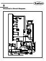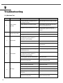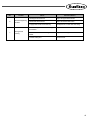
1
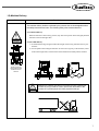
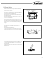
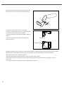
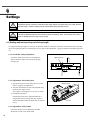
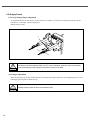
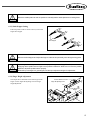
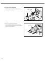
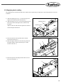
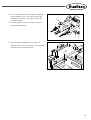
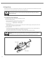
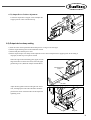
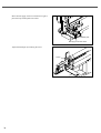
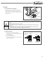
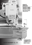
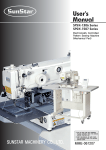
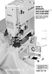
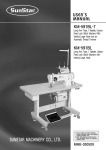
R
USER S MANUAL
SJS/A-BA2
Direct-Drive, Automatic
2-Needle Belt Loop
Sewing Machine
lity
a
u
tQ
Besst Pricevice
Be st Ser
Be
1. Thank you for purchasing our product. Based on the rich expertise and
experience accumulated in industrial sewing machine production, SUNSTAR
will manufacture industrial sewing machines, which deliver more diverse
functions, high performance, powerful operation, enhanced durability, and
more sophisticated design to meet a number of user’s needs.
2. Please read this user’s manual thoroughly before using the machine. Make
sure to properly use the machine to enjoy its full performance.
3. The specifications of the machine are subject to change, aimed to enhance
product performance, without prior notice.
4. This product is designed, manufactured, and sold as an industrial sewing
machine. It should not be used for other than industrial purpose.
R
SunStar CO., LTD.
Contents
1. Safety Rules -------------------------------------------------------------------------------------------- 6
1-1) Safety Stickers ------------------------------------------------------------------------------------- 6
1-2) Machine Delivery ---------------------------------------------------------------------------------- 7
1-3) Machine Installation ------------------------------------------------------------------------------ 8
1-4) Machine Operation ------------------------------------------------------------------------------- 8
1-5) Repair and Maintenance ------------------------------------------------------------------------ 9
1-6) Type of Safety Labels ---------------------------------------------------------------------------- 9
1-7) Location of Safety Labels --------------------------------------------------------------------- 10
2. Machine Type and Specifications ---------------------------------------------------------- 11
2-1) Machine Type ------------------------------------------------------------------------------------ 11
2-2) Specifications ------------------------------------------------------------------------------------ 11
3. Preparation ------------------------------------------------------------------------------------------- 12
3-1) Installation Environment ----------------------------------------------------------------------- 12
3-2) Electricity Environment ------------------------------------------------------------------------ 12
3-3) Parts Name --------------------------------------------------------------------------------------- 13
3-4) Machine Installation ---------------------------------------------------------------------------- 14
3-4-1) Thread Stand Installation -------------------------------------------------------------- 14
3-4-2) Air Hose Connection -------------------------------------------------------------------- 14
4. Machine Operation -------------------------------------------------------------------------------- 15
4-1) Oil Supply ----------------------------------------------------------------------------------------- 15
4-1-1) Oil Supply Position ---------------------------------------------------------------------- 15
4-2) Needle ---------------------------------------------------------------------------------------------- 15
4-2-1) Needle Installation ----------------------------------------------------------------------- 15
4-2-2) Needle Placement ----------------------------------------------------------------------- 15
4-3) Thread ---------------------------------------------------------------------------------------------- 16
4-3-1) Upper and Lower Thread Placement ----------------------------------------------- 16
4-3-2) Bobbin Case Placement and Removal -------------------------------------------- 16
4-3-3) Tension Adjustment --------------------------------------------------------------------- 17
4-3-4) Lower Thread Winder ------------------------------------------------------------------- 18
4-3-5) Bobbin Thread Volume Adjustment ------------------------------------------------- 18
5.
---------------------------------------------------------------------------------------- 19
5-1) Adjusting the full-rotary hook timing ------------------------------------------------------- 19
5-2) Trimmer Setting --------------------------------------------------------------------------------- 21
5-3) Adjusting the Trimmer Spring ------------------------------------------------------------------ 23
4
6. Settings ------------------------------------------------------------------------------------------------- 24
6-1) Setting method depending on belt loop length ------------------------------------------ 24
6-1-1) Needle Bar Clamp Adjustment ------------------------------------------------------- 24
6-1-2) Adjustment of hook base plate ------------------------------------------------------- 24
6-1-3) Adjustment of PF position ------------------------------------------------------------- 24
6-1-4) Hook setting ------------------------------------------------------------------------------- 25
6-1-5) Supply Device Position Adjustment ------------------------------------------------- 25
6-2) Supply Device ------------------------------------------------------------------------------------ 26
6-2-1) Loop Turning Finger Adjustment ----------------------------------------------------- 26
6-2-2) Finger Adjustment ----------------------------------------------------------------------- 26
6-2-3) Limit Stopper Setting -------------------------------------------------------------------- 27
6-2-4) Finger Height Adjustment -------------------------------------------------------------- 27
6-2-5) Finger Position Adjustment ------------------------------------------------------------ 28
6-2-6) Belt Loop Handle Adjustment --------------------------------------------------------- 28
6-3) Supplying device setting ---------------------------------------------------------------------- 29
6-4) Basic setting -------------------------------------------------------------------------------------- 30
6-5) Output Device ------------------------------------------------------------------------------------ 32
6-5-1) Output Device Speed Adjustment ----------------------------------------------------32
6-5-2) Output Device Position Adjustment ------------------------------------------------- 33
6-6) Output device clamp setting ------------------------------------------------------------------ 33
6-7) Cutter ----------------------------------------------------------------------------------------------- 35
6-7-1) Loop Guide Center Matching --------------------------------------------------------- 35
6-7-2) Blade Installation ------------------------------------------------------------------------- 35
6-7-3) Pneumatic Setting for Loop Cutting System -------------------------------------- 36
6-7-4) Hammer Balance Adjustment -------------------------------------------------------- 36
6.7.5) Automatic Removal of Belt Loop Connection Part ------------------------------ 37
6-8) Trimmer -------------------------------------------------------------------------------------------- 37
6-8-1) Trimmer ------------------------------------------------------------------------------------- 37
6-8-2) Trimmer Speed Adjustment ----------------------------------------------------------- 37
7. Maintenance ------------------------------------------------------------------------------------------ 39
7-1) Regular Checkpoints --------------------------------------------------------------------------- 39
7-2) Oil Supply ----------------------------------------------------------------------------------------- 39
7-2-1) Arm ------------------------------------------------------------------------------------------ 39
7-2-2) Hook ----------------------------------------------------------------------------------------- 40
7-3) Cleaning ------------------------------------------------------------------------------------------- 40
7-4) Waste Oil ------------------------------------------------------------------------------------------ 40
8. Pneumatic Circuit Diagram ------------------------------------------------------------------- 41
9. Troubleshooting ------------------------------------------------------------------------------------ 42
9-1) Machine Part ------------------------------------------------------------------------------------- 42
5
1
Safety Rules
1.1) Safety Stickers
The safety stickers in this user’s manual are divided into Caution , Danger , and Warning . They indicate that if the
safety rules are not kept, injury or damage to machine might occur as a result.
No.
Name
Description
Caution
If the machine is not properly handled, it may cause injury to
users or physical damage to the machine.
Warning
If the machine is not properly handled, it may cause death or
severe injury to users.
Danger
If the machine is not properly handled, it may cause death or
severe injury to users, and the urgency of the danger is very
high.
Caution
Warning
Danger
6
1.2) Machine Delivery
Mark
Description
The machine delivery shall be conducted by the persons who are knowledgeable about
the safety instructions and rules. The following safety rules must be observed:
2.2.1) Manual delivery
When the machine is delivered by persons, they shall wear special shoes and tightly hold the
machine on the left and right sides.
Danger
2.2.2) Forklift delivery
1) A forklift shall be big enough to endure the weight of the sewing machine and carry the
machine.
2) Use the palette when lifting the machine. Set the center of gravity of the machine (center
of the left and right sides) at the fork arm of the forklift and carefully lift the machine.
Ban people from
standing under the
machine and remove
obstacles near the
machine.
Warning
Make sure to maintain the balance of the machine when unloading the
machine by using a forklift or crane to prevent the deformation of the
machine or to prevent people from being exposed to danger.
7
1.3) Machine Installation
Depending on the installation environment, function errors, breakdown, or other physical
damage might result. Make sure to meet the following conditions for machine installation:
Caution
1) The workbench or table where the machine is installed should be durable enough to endure
the weight of the machine (see the name plate).
2) Dust and humidity are the cause of machine pollution and erosion. Please install an air
conditioner and conduct regular maintenance of the machine.
3) Install the machine at the place where it is not exposed to direct sunlight (if the machine is
exposed to direct sunlight for a long time, it may cause discoloration or deformation).
4) Secure the space around the machine. Place the machine at least 50cm away from the left,
right, and rear walls to secure sufficient space for maintenance activities.
5) Explosion risk : To prevent possible explosion, immediately stop the machine operation if
there are inflammable materials in the air.
6) Lighting : The machine does not offer lighting devices. When necessary, install needed
lighting.
7) Overturn risk : Do not install the machine on the unstable stand or table. If the machine
drops, it may cause injury or severe impact on the machine. If the machine is suddenly
stopped or the external impact is imposed, the machine might be capsized.
1.4) Machine Operation
SJS/A-BA2 was designed to conduct sewing on fabric or similar materials. Caution and
Warning labels are attached to the machine body to stress the observation of safety
directions. Make sure to comply with the followings during the machine operation.
Warning
8
1) Before turning on the power, read this manual thoroughly and have a full understanding of
machine operation.
2) Get properly dressed. Long hair, necklace, bracelet, or wide sleeve might be fed into the
machine during operation. Wear slip-free shoes to prevent slipping on the floor.
3) Check the moving scope of machine before its operation to find out whether the scope is
proper.
4) Keep hands and head away from the machine parts where accidents might occur (needle,
hook, thread take-up lever, pulley, etc.) during operation.
5) Do not remove the safety cover which protects pulley and shaft during machine operation
for user’s safety.
6) Cut the power supply before disassembling the electric box such as the control box, and
double-check that the power switch is“Off.”
7) Make sure that the power switch is“Off”when the upper shaft is manually rotated.
8) Stop the machine when the needle is replaced or when inspecting the machine after sewing
work is done.
9) Make sure to follow the cautions below. Otherwise, physical damage to the machine such as
malfunction and breakdown might result:
- Do not put articles on the S/M table.
- Avoid using a crooked needle or the needle with damaged tip.
- Use the presser foot appropriate to working conditions.
1.5) Repair and Maintenance
When machine repair is needed, it shall be conducted by SunStar A/S engineers only
who have finished the due training course.
1) For cleaning and repair, cut the main power supply. Wait for 4 minutes before starting
maintenance to make the machine completely discharged.
For main shaft motor and X,Y drive box, it takes 10 minutes before they
are completely discharged after the main power supply is cut.
Danger
Caution
2) Do not modify the machine specifications or parts without substantial consultations with
SunStar. Otherwise, it may threaten safety during machine operation.
3) Use the parts manufactured by SunStar to repair or replace the machine parts during A/S
service.
4) When repairing is completed, re-install all the removed safety covers.
1.6) Type of Safety Labels
CAUTION
경 고
Do not operate without finger guard and
safety devices. Before threading, changing
bobbin and needle, cleaning etc. switch
off main switch.
손가락 보호대와 안전장치 없이 작동하지
마십시오.
실, 보빈, 바늘교환시나 청소전에는 반드시
주전원의 스위치를 꺼 주십시오.
Do not operate without finger guard and safety devices. Before
threading, changing bobbin and needle, and cleaning, turn off the
main switch.
WARNING
경 고
Hazardous voltage will cause injury.
Be sure to wait at least 360 seconds
before opening this cover after turn off
main switch and unplug a power cord.
고압 전류에 의해 감전될 수 있으므로 커버를
열 때는 전원을 내리고 전원 플러그를 뽑고 나
서 360초간 기다린 후 여십시오.
WARNING
Injury may be caused by winding.
Be sure to turn off the power
before cleaning, lubricating,
adjusting or repairing.
High voltage will cause injury. Be sure to wait for at least 360
seconds after turning off the main switch and unplugging a power
cord if the cover needs to be opened.
Injury may be caused by winding.
Be sure to turn off the power before cleaning, lubricating, adjusting
or repairing.
9
1.7) Location of Safety Labels
WARNING
Injury may be caused by winding.
Be sure to turn off the power
before cleaning, lubricating,
adjusting or repairing.
CAUTION
경 고
Do not operate without finger guard and
safety devices. Before threading, changing
bobbin and needle, cleaning etc. switch off
main switch.
손가락 보호대와 안전장치 없이 작동하지
마십시오.
실, 보빈, 바늘교환시나 청소전에는 반드시
주전원의 스위치를 꺼 주십시오.
WARNING
경 고
Hazardous voltage will cause injury.
Be sure to wait at least 360 seconds
before opening this cover after turn off
main switch and unplug a power cord.
고압 전류에 의해 감전될 수 있으므로 커버를
열 때는 전원을 내리고 전원 플러그를 뽑고 나
서 360초간 기다린 후 여십시오.
10
2
Machine Type and Specifications
2.1) Machine Type
Machine Type
S J S / A - BA 2
SunStar
Jean
2 Needle
System
Belt Loop Attacher
Series
2.2) Specifications
Model Type
SJS/A-BA2
Sewing Speed
100~2,800RPM
Belt Loop Length
30~85mm
Belt Loop Width
8~22mm
Sewing Range (X, Y)
X: 22mm
Y: 3.2mm
Max. Sewing Speed
Up to 2,800spm
Stitch Length
0.1~10mm
Needle in Use
MR4.0, 4.5
Hook in Use
All-direction revolving vertical large hook (2x)
Presser Foot Lift
Up to 21mm
Average Production
1,900 units (8 hrs 5 loops)
Sensor
10
Solenoid
18 (14 for supplying devices + 4 for sewing machine)
Memory
P-ROM
Table Height Adjustment
300mm
No. of Input Patterns
Up to 99 patterns
Motor Specifications
550W AC Servo Motor
Power consumption
600VA
Feed System
Pulse motor
Operating Temperature
5°C ~ 40°C
Operating Humidity
20%~80%
Pneumatic Pressure in Use
0.5Mpa (5kgf/cm2)
Power Supply
1-Phase : 100~240V, 3-Phase : 200~440V, 50/60Hz
11
3
Preparation
3.1) Installation Environment
1) Do not use the machine if the voltage is 10% higher than the rated voltage to prevent accidents caused by wrong
operation.
2) Check the appropriateness of the pressure of pneumatic devices such as air cylinder to prevent accidents caused by wrong
operation.
Observe the installation environment as set forth in the manual to make sure of proper operation of the
machine. Otherwise, unexpected errors might occur.
Warning
3) Operating temperature
: 0°C ~ 40°C (32°F~ 104°F)
4) Storage temperature
: -25°C ~ 55°C (-13°F~ 131°F)
5) Operating humidity
→ Relative humidity : 45% ~ 85%
3.2) Electricity Environment
The power voltage used should be within the range of ±10% of the rated voltage.
Warning
1) Power Voltage
- The power voltage used should be within the range of ±10% of the rated voltage.
- The power frequency used should be within the range of ±1% of the rated frequency (50/60Hz).
2) Electromagnetic Wave Noise
- The sewing machine should not share the power outlet with the product having powerful magnetic field or high
frequency. They should be placed away from each other.
3) Take caution not to spill water and coffee into the control box and the motor.
4) Do not drop the control box and the motor.
12
3.3) Parts Name
Lubrication Device
Arm
Table
Operation Box
Cutter
Bed
Output Device
Sliding Device
Control Box
Supply Device
13
3.4) Machine Installation
3.4.1) Thread Stand Installation
Assemble and install the thread stand.
3.4.2) Air Hose Connection
To connect the air hose, insert the quick joint sockets
into the quick joint plugs attached to the regulator.
To adjust the pneumatic pressure, lower the adjusting
lever and use the gauge.
Caution
14
1) Maintain the proper air pressure level of 5 bar (0.5mkf).
2) If the air pressure falls below 5bar, error message appears and the air pressure adjusting switch is
activated to stop the machine operation (error message: Err 24 (Low Pressure!)).
3) When the power is off, the remaining air is released and the remaining pressure is removed.
4
Machine Operation
4.1) Oil Supply
4.1.1) Oil Supply Position
- When initially operating the sewing machine, check the remaining oil volume through the oil window and if it is
insufficient, supply more oil.
4.2) Needle
4.2.1) Needle Installation
Loosen the needle fixing screw on the needle bar. With
the long needle grooves headed against each other, insert
the needle until the upper section of the needle reaches
the end of the needle hole on the needle bar. Then use
the fixing screw to fix the needle.
4.2.2) Needle Placement
Move the thread take-up lever to the highest position and
place thread on the needle. As in the right-side figure,
place the needle.
Reference
Light material device is optional. Light materials can be sown after installing the light materialdedicated device. Only when the replacement with the right device is made, sewing quality can be
guaranteed.
15
4.3) Thread
4.3.1) Upper and Lower Thread Placement
1) Upper Thread Placement
Place the thread take-up lever at the highest position
and make the thread pass through the main and
subordinate thread adjusting devices as in the figure.
2) Lower Thread Placement
Insert the bobbin into the bobbin case. Pass the
thread through the thread slot ① and the tension
adjusting plate spring ②.
①
②
4.3.2) Bobbin Case Placement and Removal
Open the left/right cover and push the bobbin into the
hook with the bobbin handle held until a click sound is
heard.
Caution
16
1. For bobbin replacement, the power must be turned off.
2. If the machine is operated with the bobbin case improperly placed, thread entanglement or bobbin
case ejection might occur.
4.3.3) Tension Adjustment
Note
When the machine is released from
factory, the default tension value is set.
When necessary, adjustment is needed.
1) Upper Thread Tension Adjustment
Turn the main and subordinate tension adjusting nuts
clockwise to get the upper thread tension stronger. If
they are turned counter-clockwise, the tension gets
weaker.
The thread tension should be adjusted depending on
fabric, thread, stitch number, and other sewing
conditions.
2) Thread Take-up String Tension Adjustment
The thread take-up string tension can be adjusted by
turning the bolt for the main thread adjusting device
shaft with a drive. Clockwise turning makes the
thread take-up spring tension stronger, and vice
versa. (Standard moving range is 6~8mm, and
standard tension is 30~50g).
3) Lower Thread Tension Adjustment
The lower thread tension can be adjusted by turning
the tension adjusting screw on the bobbin case ①.
Clockwise turning makes the lower thread tension
stronger, and vice versa.
①
17
4.3.4) Lower Thread Winder
1) Insert the bobbin into the thread winder shaft on the
thread winder base which is attached to the top cap.
2) Connect the thread winder lever to the bobbin and
press the start button.
3) When the thread winder lever is separated from the
bobbin, cut the bobbin thread using the thread winder
blade.
4.3.5) Bobbin Thread Volume Adjustment
When the thread winder adjusting plate to adjust the
wound thread volume on the bobbin. Move the plate to
A direction if the thread volume is big, and move the
plate to B direction if the thread volume is small.
Bobbin
Thread Winder
Adjusting Plate
18
5
5-1) Adjusting the full-rotary hook timing
SunStar machine uses two full-rotary large hooks and two needles. It also uses MR4.5 needle.
When adjusting the position of the hook timing, two full-rotary hooks (including inner and outer hooks) shall be at the center
of the needle at the same time.
Besides, when the needle is at the lowest position, check the
height of the needle bar, and make sure that the needle hole
is covered two-third by the needle.
Upon threading, the thread should be not restricted to
motion inside the needle at the lowest needle position.
Separate the bobbin from the bobbin case and loosen the
hook tightening screw for setting.
The needle bar moves at the range of 2mm to 2.2mm.
The full-rotary hook point is located at the center of the
needle, and it should pass by the needle while slightly
touching it within the distance from 0.05mm to 0.1mm from
the needle.
0.05~1.0mm
Needle
Lift the needle bar and separate the bobbin from the bobbin
case. Tighten the hook tightening screw for setting.
(Horizontal, vertical, shaft rotating direction)
Needle
thread
19
1) To adjust the hook holder, loosen the hook holder tightening screw and set the distance between the hook holder and the hook at
1mm(vertical direction).
2) To adjust the hook inside the hook holder which is at the center of the needle, loosen the hexagon tightening screw located within
the hook holder base (horizontal direction).
3) To align the hook face with the center of the hook shaft, loosen the hexagon tightening screw within the hook holder base (rotating
direction).
Check the location of the full-rotary hook and find the timing when the needle is not touched during its
entry into the hook needle hole.
Caution
1mm
0.05mm~1.0mm
Needle
20
5-2) Trimmer Setting
SunStar machine is electronically adjusted and adopts the
air pressure-driven trimmer.
needle plate
adjusting screw
The trimmer is attached to the base, which can be adjusted
horizontally, using two clamping screws.
The scaled screws fixed to the face plate are positioned at
the height of the block.
The block should be always rolled up in order to ensure the
screw touch the needle plate.
The moving blade is driven by the cylinder, and moves into
the triangle formed by the thread, the needle and the bobbin.
Slightly lower the needle until the blade passes through the
triangle.
adjusting screw
The blade position, full design, and thread cutter are
described.
The hook tip should slight pass by.
- Left to the needle when it is viewed from the inner head
- Right to the needle when it is viewed from the outer head
Needle
Edge Point
At the highest position, the tip of the blade should be at least
1.5mm above the hook holder. This is to ensure the both
threads are held.
To adjust the position of the blade, loosen the trimmer lever
tightening screw.
1~1.5mm
21
When touched, the fixed blade should overlap the moving
blade at least 1mm at the inner side of the moving blade.
1mm
To check the proper trimming motion of the blade,
manually move the trimmer cylinder to check its operation.
The position of the fixed blade can be adjusted.
-Loosen the clamping screw of the fixed blade to adjust its
position.
-Loosen the clamping screw of the fixed blade base to
adjust the pressure.
tightening screw
tightening screw
Manually operate the trimmer cylinder to ensure that the trimming is conducted with minimum pressure based on the parallel
alignment with the blade and that trimming quality is appropriate. To check if the blades are horizontally located,
-Remove the thread cutter’
s upper thread holder.
-Move the thread picker forward and mark the upper part in black using a marker.
-Move the hook forward or backward and check if the fixed blade passes by horizontally after touching the color at the
contact area.
To check good quality of trimming, use the four upper threads for final test.
22
5-3) Adjusting the Trimmer Spring
The top of the upper thread holder is located at the blade base where the fixed blade is located.
The top of the upper thread holder has the safety function to prevent the early trimming by the fixed blade, meaning that the
remaining thread to the needle can be prevented from being too short.
Caution
The surface of the thread route should not have burrs and blades. To prevent the blade shaft from
escaping from the alignment with the fixed blade, do not apply excessive pressure to the moving blade
shaft of the upper thread holder. Please see the arrangement of the upper thread holder as in the figure
below.
upper 3
upper 1
upper 4
upper 2
23
6
Settings
SJS/A-BA2 sewing machine is composed of the supply device, the output device, the cutter, and the
trimmer. Keep in mind the setting method of the devices during the machine use.
Caution
The size of adjusted areas should be identical. When the setting is done, check if there is any risk of
clash or damage due to the step moving activity.
Caution
6.1) Setting method depending on belt loop length
To change the belt loop length, it is necessary to adjust the needle bar clamp, the external PF, the hook base plate, the sliding
device, the input/output device, and the finger. For easy and accurate adjustment, a gauge is attached to the adjusting parts for
use.
6.1.1) Needle Bar Clamp Adjustment
Loosen the needle bar clamp screw and adjust the
distance between needles in line with the belt loop
sewing scope.
Tightening screw
6.1.2) Adjustment of hook base plate
1) Spin the fixing lever on the slide plate to move the
bed for stopper screw adjustment.
2) The hook base distance can be easily adjusted using
the hook base stopper screws.
The stopper screw length is set at 45, 50, 55, 60mm.
3) Feed plate replacement
If the distance from newly adjusted needle bar is
inappropriate for the existing feed plate, replace it
with the feed plate offered as default item or optional
device.
6.1.3) Adjustment of PF position
Loosen the fixing screw for adjustment and make
adjustment as same as the needle width.
24
Adjusting screw
Lever
6.1.4) Hook setting
Move the position of the sensor that detects the base
separation and maintain the grounding distance at 1mm.
Sensor
6.1.5) Supply Device Position Adjustment
1) Loosen the sensor plate fixing lever that fixes the
sensor plate. Use the jig handle for moving the slide
plate and Set No. 1 finger to be in the same position
as the presser foot.
2) Loosen the finger fixing screw and adjust No. 2
finger to be in the same position as the presser foot.
3) Use the sliding device to move the supplying device
base and overlap the cutting device and the closely
linked belt loop rotary finger with the needle plate
hole. And then conduct the manual testing for the
stable placement of the sewing fabric.
Handle
Fixing lever
25
6.2) Supply Device
6.2.1) Loop Turning Finger Adjustment
To change the distance between fingers, use the socket set screw(M6) ① at the bottom of the finger shaft base and the
bolt (M4) ② on the finger cylinder support plate.
(default setting: 55mm)
①
②
③
The distance should be adjusted while ① and ② are all unfastened. Otherwise, the forced operation
could cause damage to the machine for which the company is not liable.
Caution
6.2.2) Finger Adjustment
When inserting the loop, the loop could smoothly move between the fingers. Otherwise, use the tightening bolt ③ on the
mid-finger supporting base to adjust the loop.
Adjust the finger location to fix the loop between fingers.
Caution
26
Match the needle plate hole and the position to manually test the stable placement of sewing fabric.
Caution
6.2.3) Limit Stopper Setting
If the loop used is wide at 15mm or above, remove the
finger limit stopper.
Limit Stopper
Remove the limit stopper and adjust the finger to make the loop smoothly move along the loop guide.
Caution
Caution
Depending on the change in width, the belt loop input changes accordingly. Therefore, sometimes the
supplying device position sensor might have a problem in detection. When error occurs to the position
detection, adjust the position sensor properly.
When the input changes to a great degree, use the input adjustment stopper for adjustment.
6.2.4) Finger Height Adjustment
The output device should be at the same height of the
finger. Use the finger lift adjusting screw for finger
height adjustment.
Position detection sensor
Finger lift adjusting screw
Input adjustment
stopper
27
6.2.5) Finger Position Adjustment
When the finger is inserted into the belt, the belt is
supposed to move 0.2mm for accurate fixation. To make
it sure, adjust the bumper bolt.
Cylinder stopper
Bumper bolt
6.2.6) Belt Loop Handle Adjustment
Whenever different belt loop materials and types are
used, use the adjusting screw for the belt loop handle to
make sure of accurate fixation.
28
Adjusting screw
6.3) Supplying device setting
The supplying device includes the input device and the device of delivering cut belt loop to the sewing machine. It can be set
as follows:
1) Adjust the tightening screw ① to make the finger base
support bar located in parallel with the floor.
2) Adjust the finger screw ② to locate the supplying device
5mm away from the feed plate when it settles on the
feed plate.
Adjust to make sure that the belt loop does not interfere
with the feed plate and the PF.
3) Detect the position of the cylinder when it moved
backward to maximum. ③
4) When the finger holder moves forward, the position for
the finger holder to capture the belt loop in a stable
manner is detected. ④
Tightening screw ①
Tightening screw ②
③
④
5) Detect the position of the finger holder when it moves
forward to maximum. ⑤
⑤
29
6.4) Basic setting
When the machine is released from factory, it is set with default values. When additional setting is
necessary only, please change the default setting.
Caution
1) Change the position of the filler presser spring collar's
fixing screw ③ to adjust the pressure. The loop bracket
plate should press the belt loop with appropriate
pressure. If so, when the output device holds the belt, the
finger holder can easily hold the belt loop.
2) Adjust the fixing screw ① to place the filler's position at
the center of the belt.
①
②
3) If the finger holder does not function properly, unfasten
the tightening screw ③ to adjust the output volume of
the output device.
③
4) The belt holding error could be addressed by adjusting
the width of the finger holder ④.
5) When the output device holds the belt, it serves as the
role of guiding the belt ⑤ in the stable manner. If it is
improperly placed, the slant sewing is performed.
6) Adjust the rotary position of the ⑥ finger holder.
④
⑤
⑥
30
7) It serves an important role of bonding the belt using the
stopper tightening screw ⑦ that controls the cylinder
operation. If the position is not proper, one of the belt
sides is not bonded.
8) Loosen the tightening screw ⑧ to adjust up or down
position of the belt holder.
⑦
⑧
9) Adjust the stopper tightening screw ⑨ of the belt
supplying device to place the belt at the center when one
side of the belt is not pushed sideways. .
⑨
31
6.5) Output Device
The belt loop output device is composed of the solenoid valve, the cylinder which performs the forward/backward movement
of the output device, and the speed controller which controls the cylinder speed.
When released, the machine is set with proper speed. Please adjust the setting when additional
setting is required only.
Caution
6.5.1) Output Device Speed Adjustment
The speed controller can be used to adjust the output device speed.
[Out control-based governance]
• Moving forward: Upper cylinder and lower cylinder are same
• Moving backward : 1 step backward → upper cylinder
2 step backward → lower cylinder
1) Moving forward
With all speed controllers closed, adjust the upper cylinder speed. To make the upper cylinder speed as same as the
lower cylinder speed, adjust the speed controller.
2) Moving backward
To insert the belt loop into the supply device, the output device moves backward in 2 steps. Adjust the upper and
lower cylinder speeds properly to block excessive impact on the machine.
The middle-stop bracket position can be adjusted to change the edge length for belt loop sewing.
Caution
For output device speed, the lowest optimal speed is recommended since it influences durability of
products.
Make adjustments to the extent that they do not influence the operating speed of the machine.
Upper cylinder
Lower cylinder
32
6.5.2) Output Device Position Adjustment
Loosen the output device stopper screw and adjust the
stopper position in line with the belt loop.
Tightening
screw
6.6) Output device clamp setting
1) Press the arrow on the Operational Panel and press No. 6 Origin to set the origin.
2) Set the origin following same as the method for bartack.
3) Set the feed plate and the presser foot.
4) Set the output clamps. The clamps of the output device are critical components for supplying belts. If the setting is
improper, the belt loop is escaped or twisted.
When the edge of the belt holding plate (upper) and the
edge of the filler are at the same level, fasten the grape
guide fixing screw. (When the clamps hold the fabric)
Belt holding plate
(upper)
Filler
Adjust the belt guide on the left and right side. At this
time, the bulged part at the end of the filler should be
placed at the center of the belt and to do this adjust the
tightening screw.
Belt guide
33
Move the belt supply sensor lever shaft left or right to
place the loop bracket plate at the center.
Loop bracket plate
Belt supply sensor lever shaft
Adjust the belt length by loosening the screw.
Screw
34
6.7) Cutter
6.7.1) Loop Guide Center Matching
The belt center is at the same location. Set the center
with reference to the carved lines on the face of the
hammer slide plate. Loosen the nut and adjust the overall
blade blocks (B, C).
Block C
Block B Carved lines
Caution
1. See the operation manual on manual trimming. Make sure that cutting is made at the center of the
loop.
2. Testing pressure should be 4bar or below.
3. After adjusting the cutter, the adjusting bolt on the cutter cylinder base must be used to set the
balance.
4. To prevent damage to cutter blade, conduct the test for maintaining balance at the minimum
pressure (2bar~3.5bar), and keep the operating pressure at 5bar.
6.7.2) Blade Installation
1) Installation of fixed type cutter (optional)
Loosen the screw on the cutter base holder to install
a new cutting blade.
2) Revolving Blade Installation
Loosen the fixing bolt of the rotary cutter base and
install a new cutter blade.
Fixing screw
Cutter tension
spring
Fixed type (Optional)
Fixing bolt
Revolving type
35
6.7.3) Pneumatic Setting for Loop Cutting System
The pneumatic pressure used by the loop cutting system
should be set using the pressure adjuster as in the table
below.
Belt Loop Width
Proper Pressure of Cutting System
13~14mm
5 bar
16~20mm
5.4 bar
• Thin fabric: 5bar or below
• Thick fabric: 5bar or above
During cutting, make sure of keeping the pressure at the lowest optimal level to increase the lifespan
of cutter blades and related parts.
Caution
6.7.4) Hammer Balance Adjustment
Conduct the test at 3bar~3.5bar.
To make sure of accurate belt loop cutting, adjust the
hammer balance using the hammer balance adjusting
screw on the lower cutter cylinder base.
Manual adjusting screws
Hammer cylinder
fixing screw
Manual adjusting screws
36
Manual adjusting screws
6.3.5) Automatic Removal of Belt Loop Connection
Part
When the belt loop connection part is inserted, the
sensor-based automatic removal function of the belt loop
connection part is activated.
Loosen the sensor position adjusting screw and move the
sensor to properly adjust the distance and contact angle
from the sensor plate. This way, make the setting for
most optimized sensing conditions.
Reference
Lamp checking
Adjusting bolt
1) The belt loop connection part is operated in the following order:
• Belt loop connection part → Filler → Sensor plate → Sensor
Make adjustments to keep the sensor plate and the sensor contacted all the time.
2) Properly locate the sensor plate extension spring to prevent wrong operation caused by the sensor
plate vibration.
6.8) Trimmer
6.8.1) Trimmer
The upper and lower thread trimming of the belt loop
sewing machine is conducted simultaneously by the
most optimized pneumatic trimming mechanism.
6.8.2) Trimmer Speed Adjustment
Use the presser adjusting device to keep the trimming
speed constant.
When the machine is released, it is set at default speed. Please change the setting only when
necessary.
Caution
Caution
The pneumatic pressure of the upper trimmer basically needs adjustment depending on thread type,
operating period, machine status, and remaining thread length. Manually conduct the pneumatic
operation test. When pressing the top button of each solenoid valve, manual operation becomes
possible. (Basic pneumatic pressure: 4 bar)
37
0.5mm
Lower thread is separated by 0.5mm from the end of
the fixing blade.
Hook holder
2~2.5mm
Moving blade
Maintain the distance between the hook holder center
and the moving blade at 2mm~2.5mm.
38
Fix the fixing screw on the upper part to the moving
blade. The fixing screw on the lower part determines
the motion range.
7
Maintenance
Caution
1) The power switch must be turned off before starting maintenance activities in order to prevent
accidents arising from wrong operation.
2) Strictly observe the mechanical and electric safety rules during regular checking and maintenance.
3) SunStar is not liable for machine breakdown and wrong operation arising from irregular cleaning
and oil supply failure.
4) Use authentic SunStar parts for replacement.
7.1) Regular Checkpoints
1) Conduct regular cleaning, oil supply, and grease supply to make sure that the machine functions are maintained at the best
performance.
2) The failure in conducting a regular checkout could result in the following problems:
- Abnormal abrasion of oiled parts due to the insufficient oil and grease supply
- Abnormal operation due to the dust and foreign materials stuck in the moving parts
No.
Lubricant Type
1
Sewing machine oil
2
Grease
Frequency
Applied Part
Arm oil supply tank
Rear arm oil supply tank
When oil runs out
Slide blocks of the supply device
Hammer cylinder
Every seven days
Finger turning cylinder
(Pinion gear, rack gear)
Presser foot bracket
Roller guide
Every 30 days
Stand rack gear
Every 180 days
Grease inlet A
Grease inlet B
7.2) Oil Supply
7.2.1) Arm
Supply oil through the oil tank entrance on the upper arm.
Due to the nature of delivery, supplied oil volume might be small. Then run the valve for 1 minute or
above for proper lubrication.
Caution
39
7.2.2) Hook
Remove the cap of the most optimized hook lubrication system on the upper bed using the screwdriver and supply oil.
7.3) Cleaning
The belt loop sewing machine is equipped with an air gun. Use the air gun to remove foreign materials stuck on moving
parts.
No.
Cleaning Section
1
Around hook
2
Thread take-up lever / thread tension device
Frequency
Every day
Around moving and fixed blades
3
Every seven days
Use the air gun to remove dust around the moving
and fixed blades from the below of the needle plate.
7.4) Waste Oil
The waste oil container under the table should be emptied
when it is filled.
Table
Waste Oil
Container
Caution
40
1) When disassembling the waste container, take care to prevent oil from dropping to the floor.
2) Just in case of oil dropping to the floor, when disassembling the waste oil container, place a cloth,
paper, or oil dish on the floor.
8
Pneumatic Circuit Diagram
Before
After
41
9
Troubleshooting
9.1) Machine Part
No.
1
2
3
Trouble
Faulty machine
operation
Cause
Corrective Action
Excessive relaxation of the belt tension or
the damage to the belt
Adjust the belt tension and replace the belt
Power cutoff or the cut of the circuit fuse
Check whether the main shaft motor drive
fuse is cut and replace it if so.
Separation of feed bracket from X or Y limit
Properly place the feed bracket at the
normal position (within the scope of the limit
switch)
Loose main driving belt
Adjust the belt tension
Wrong synchro location
Adjust the synchro location
Damage to needle (crooked needle, scratch
on needle hole or groove, abrasion or
deformation of the needle tip)
Replace the needle
Wrong needle installed
Replace the current needle with proper one
Contact between needle and hook
Adjust the distance between needle and
hook properly
Improper stop position
Needle break
Wrong thread placement
4
5
42
Thread break
Stitch skip
Wrong needle installation (needle height,
needle direction, etc.)
Insert the needle again
Damaged needle (crooked needle, scratch
on needle hole or groove, abrasion or
deformation of the needle tip)
Replace the needle
Too strong upper and lower thread tension
Adjust the tension
Excessive thread take-up lever spring
tension and moving scope
Adjust the thread take-up lever spring
tension and moving scope
Crooked needle
Replace the needle
Improper needle for thread used
Replace the needle
Bad needle fitting condition
Refit the needle
Improper needle and timing
Readjustment of needle and hook timing
Inappropriate groove and large gap from
hook point
Readjustment of needle and hook timing
Excessive thread take-up lever spring
tension and moving scope
Adjust the thread take-up lever spring
tension and moving scope
No.
6
7
Trouble
Bad thread tightening
condition
Missing thread
trimming
Cause
Corrective Action
Weak upper thread tension
Adjust the upper thread tension
Weak lower thread tension
Adjust the lower thread tension
Inappropriate needle and hook timing
Readjustment of needle and hook timing
Loose crossing tension between moving and
fixed blades
Adjust the tension of the fixed blade
Scratch or abrasion on the moving and fixed
blades
Replace the moving and fixed blades
Trimmer setting error
Trimmer reset
43