1
Power Analyzer
Communication Interface
IM 253710-11E
2nd Edition
Introduction
Thank you for purchasing YOKOGAWA’s PZ4000 Power Analyzer.
This Communication Interface User’s Manual describes the functions and commands of
the GP-IB and serial interfaces. To ensure proper use of the GP-IB/serial interfaces,
please read this manual thoroughly.
Keep the manual in a safe place for quick reference whenever a question arises.
Two manuals are provided with the PZ4000 including this Communication Interface
User’s Manual.
Manual Name
Manual No.
Description
PZ4000 Power Analyzer
User’s Manual
IM 253710-01E
Describes all functions except for the
communications functions and operation
procedures of the instrument.
PZ4000 Power Analyzer
Communication User’s Manual
IM 253710-11E
Describes the communications functions of
the GP-IB/serial interface.
Note
• The contents of this manual are subject to change without prior notice as a result of
improvements in instrument’s performance and functions.
• Every effort has been made in the preparation of this manual to ensure the accuracy
of its contents. However, should you have any questions or find any errors, please
contact your nearest YOKOGAWA representative listed on the back cover of this
manual.
• Copying or reproduction of all or any part of the contents of this manual without
YOKOGAWA’s permission is strictly prohibited.
Trademarks
• IBM PC/AT is a registered trademark of International Business Machines Corporation..
• Other product names are trademarks or registered trademarks of their respective
holders.
Revisions
1st Edition: April 1999
2nd Edition: April 2000
Disk No. BA32
2nd Edition: April 2000
All Rights Reserved, Copyright © 1999 Yokogawa Electric Corporation
IM 253710-11E
i
How to Use this Manual
Structure of this Manual
This User’s Manual consists of five chapters, an Appendix and an Index as described
below.
Chapter 1
Overview of the GP-IB Interface
Describes the functions and specifications of GP-IB.
Chapter 2
Overview of the Serial Interface
Describes the functions and specifications of serial.
Chapter 3
Before Programming
Describes formats used when sending a command.
Chapter 4
Command
Describes each command.
Chapter 5
Status Report
Describes the status byte, various registers and queues.
Chapter 6
Sample Programs
Sample programs, written in Quick-BASIC, for MS-DOS/V machines
equipped with the following GP-IB board: AT-GPIB/TNT IEEE-488.2, from
National Instruments.
Appendix
Contains references including the ASCII character code table.
Index
Provides an alphabetically ordered index.
Conventions Used in this Manual
• Symbols used for Notes and Keys
Type
Symbol
Description
Unit
k
K
1000
1024
Note
Note
Provides information that is necessary for proper operation of the
instrument.
Key
[Comm Device] Refers to a soft key displayed on the screen.
e.g.: 100 kS/s (sample rate)
e.g.: 640 KB (floppy disk memory capacity)
• Symbols used in syntax descriptions
Symbols which are used in the syntax descriptions in Chapter 4 are shown below.
These symbols are referred to as
ii
Symbol Description
Example
Example of Input
<>
Defined value
CHANnel <x> <x>=1 to 8
→CHANNEL2
{}
|
One of the options in {} is selected. COUPling {AC|DC|GND}
Exclusive OR
[]
Abbreviated
→COUPLING AC
TRIGger [:SIMPle]:SLOPe →TRIGger:SLOPer
IM 253710-11E
1
Contents
Introduction ...................................................................................................................................... i
How to Use this Manual ................................................................................................................. iii
2
Chapter 1 Overview of the GP-IB Interface
1.1
1.2
Names of the Parts and Their Functions ........................................................................... 1-1
Connecting the GP-IB Cable ............................................................................................. 1-2
1.3
1.4
GP-IB Interface Functions ................................................................................................. 1-3
GP-IB Interface Specifications .......................................................................................... 1-4
1.5
1.6
Setting Addressable Mode ................................................................................................ 1-5
Response to Interface Messages ...................................................................................... 1-6
Chapter 2 Overview of the Serial Interface
4
5
2.1
2.2
Names of the Parts and Their Functions ........................................................................... 2-1
Serial Interface Functions and Specifications ................................................................... 2-2
2.3
2.4
Connecting the Serial Interface Cable .............................................................................. 2-3
Handshaking ..................................................................................................................... 2-5
2.5
2.6
Matching the Data Format ................................................................................................. 2-7
Setting up this Instrument ................................................................................................. 2-8
6
App
Chapter 3 Before Programming
3.1
3.2
Messages .......................................................................................................................... 3-1
Commands ........................................................................................................................ 3-3
3.3
3.4
Response .......................................................................................................................... 3-5
Data ................................................................................................................................... 3-5
3.5
Synchronization with the Controller ................................................................................... 3-7
Chapter 4 Commands
4.1
Command Listing .............................................................................................................. 4-1
4.2
4.3
ABORt Group .................................................................................................................. 4-11
ACQuire Group ............................................................................................................... 4-11
4.4
4.5
CHANnel Group .............................................................................................................. 4-12
COMMunicate Group ...................................................................................................... 4-16
4.6
4.7
CURSor Group ................................................................................................................ 4-18
DISPlay Group ................................................................................................................ 4-23
4.8
4.9
FILE Group ...................................................................................................................... 4-33
HCOPy Group ................................................................................................................. 4-37
4.10 IMAGe Group .................................................................................................................. 4-40
4.11 INPut Group .................................................................................................................... 4-41
4.12 MATH Group ................................................................................................................... 4-53
4.13 MEASure Group .............................................................................................................. 4-56
4.14 NULL Group .................................................................................................................... 4-61
4.15 NUMeric Group ............................................................................................................... 4-62
4.16 SETup Group .................................................................................................................. 4-69
4.17 SSTart Group .................................................................................................................. 4-70
4.18 STARt Group ................................................................................................................... 4-70
4.19 STATus Group ................................................................................................................. 4-71
4.20 STOP Group ................................................................................................................... 4-72
4.21 SYSTem Group ............................................................................................................... 4-73
IM 253710-11E
3
iii
Index
Contents
4.22 TIMebase Group ............................................................................................................. 4-76
4.23 TRIGger Group ............................................................................................................... 4-77
4.24 WAVeform Group ............................................................................................................ 4-80
4.25 ZOOM Group .................................................................................................................. 4-83
4.26 Common Command Group ............................................................................................. 4-85
Chapter 5 Status Report
5.1
5.2
Overview of the Status Report .......................................................................................... 5-1
Status Byte ........................................................................................................................ 5-2
5.3
5.4
Standard Event Register ................................................................................................... 5-3
Extended Event Register .................................................................................................. 5-4
5.5
Output Queue and Error Queue ........................................................................................ 5-5
Chapter 6 Sample Program
6.1
Before Programming ......................................................................................................... 6-1
6.2
6.3
Example of Normal Measurement Data Output ................................................................ 6-2
Example of Harmonic Measurement Data Output ............................................................ 6-5
6.4
6.5
Output Example of Waveform Data in ASCII Format ........................................................ 6-7
Output Example of Waveform Data in Binary Format ....................................................... 6-9
Appendix
Appendix 1 ASCII Character Code ....................................................................................... App-1
Appendix 2 Error Messages ................................................................................................. App-2
Appendix 3 Overview of IEEE 488.2-1987 ........................................................................... App-4
Index
iv
IM 253710-11E
Chapter 1 Overview of the GP-IB Interface
1
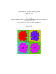
1.1 Names of the Parts and Their Functions
POWER ANALYZER
DC - 2 MHz 5 MS/s
CONFIGURATION
TRIG’ D
ESC
RES
SETUP INPUT MEASURE TRIGGER
ET SELECT
ACQ
DISPLAY MATH CURSOR ZOOM
REMOTE indicator
Lit while remote mode is
active via communications.
REMOTE
FILE
MISC
HELP LOCAL
COPY
NULL
CAL
FILTER
FILTER
SHIFT
MENU
ELEMENT
FILTER
1
2
3
FILTER
SINGLE
START
ABORT
4
START/STOP
OBSERVATION TIME
CH 1 CH 3 CH 5 CH 7 VOLTAGE
CH 2 CH 4 CH 6 CH 8 CURRENT
POWER
O
I
LOCAL key
Press this key to switch from remote
mode to local mode so as to enable
key operation.
MISC key
Press this key to set communication setting.
Rear Panel
GP-IB connector
Used to connect a controller
(personal computer etc.)
using a GP-IB cable.
For information on how to
connect the GP-IB cable,
refer to the following page.
IM 253710-11E
1-1
Overview of the GP-IB Interface
Front Panel
1.2 Connecting the GP-IB Cable
GP-IB Cable
The GP-IB connector on the side panel of the PZ4000 is a 24-pin connector that
conforms to IEEE Standard 488-1978. Use a GP-IB cable that also conforms to IEEE
Standard 488-1978.
Connection Method
Connect the GP-IB cable as shown below.
Connection Precautions
• Be sure to tighten the screws on the GP-IB cable connector firmly.
• The instrument can be connected to more than one item of equipment (e.g. a personal
computer) if more than one GP-IB cable is used. However, it is not possible to
connect more than 15 items of equipment (including the controller) to a single bus.
• If you connect the instrument to more than one item of equipment, make sure that a
different address is used for each item.
• Each connecting cable must be 2 m or less in length.
• The total length of all the cables must not exceed 20 m.
• While communications are in progress, more than two-thirds of the connected
equipment items must be turned ON.
• When connecting more than one item of equipment, connect them so that the
connection route forms a star or linear configuration. Loop or parallel wiring is not
allowed.
CAUTION
Be sure to switch off power to both your PC and the oscilloscope before
connecting or disconnecting cables. Failure to switch power off may
cause internal circuit failure or improper operation.
1-2
IM 253710-11E
1
1.3 GP-IB Interface Functions
Listener function
• Allows you to make the settings which you can make using the panel keys on the
instrument, except for the power ON/OFF and GP-IB communications settings.
• Receives commands from a controller requesting output of set-up and waveform data.
Also receives status report commands.
Talker function
• Outputs set-up and waveform data.
Note
The talk-only, listen-only and controller functions are not available on this instrument.
Switching between Remote and Local Modes
When switched from Local to Remote Mode
Remote mode is activated when a REN (Remote Enable) message is received from a
controller while local mode is active.
• REMOTE is displayed on.
• All front panel keys except the LOCAL key can no longer be operated any more.
• Settings entered in local mode are retained.
When switched from Remote to Local Mode
Pressing the LOCAL key in remote mode puts the instrument in local mode. However,
this is not possible if Local Lockout has been set by the controller (page 1-6).
• The REMOTE indicator is turned off.
• All front panel keys are operative.
• Settings entered in remote mode are retained.
IM 253710-11E
1-3
Overview of the GP-IB Interface
GP-IB Interface Functions
1.4 GP-IB Interface Specifications
GP-IB Interface Specifications
Electrical and mechanical specifications : Conforms to IEEE Standard 488-1978.
Interface functions
Protocol
: Refer to the table below.
: Conforms to IEEE Standard 488.2-1987.
Code
Mode
: ISO (ASCII) code
: Addressable mode
Address setting
: Addresses 0 to 30 can be selected from the
GP-IB setting screen, displayed when you
press the MISC key.
: Remote mode can be cleared by pressing the
Remote mode clear
LOCAL key. However, this is not possible if
Local Lockout has been set by the controller.
Interface functions
1-4
Function
Subset Name
Description
Source handshaking
SH1
Full source handshaking capability
Acceptor handshaking
AH1
Full acceptor handshaking capability
Talker
T6
Basic talker capability, serial polling, untalk on
MLA (My Listen Address), no talk-only
capability
Listener
L4
Basic listener capability, unlisten on MTA (My
Talk Address), no listen-only capability
Service request
SR1
Full service request capability
Remote local
RL1
Full remote/local capability
Parallel poll
PP0
No parallel polling capability
Device clear
DC1
Full device clear capability
Device trigger
DT1
Device trigger capability
Controller
C0
No controller function
Electrical characteristic
E1
Open collector
IM 253710-11E
1
1.5 Setting Addressable Mode
When you make settings which can be made using the front panel keys of the instrument
or when you output set-up data or waveform data using the controller, the following
settings must be made.
Setting the address
This function allows you to set the instrument’s address for addressable mode within the
range of 0 to 30. Each item of equipment connected via a GP-IB interface has its own
address, by which it can be identified. Care must be taken to ensure that all
interconnected devices are assigned unique addresses.
Note
Do not change the address while the GP-IB interface is being used by the controller.
Operationg Procedure
1.
2.
Press the MISC key.
Press the “GP-IB/RS232” soft key.
3.
4.
Press the “Comm Device” soft key to select “GPIB.”
Turn the jog shuttle to set the desired address.
Step 1, 2
IM 253710-11E
Step 3
Step 4
1-5
Overview of the GP-IB Interface
Before You Begin
1.6 Response to Interface Messages
Response to Interface Messages
Response to a uni-line message
IFC (Interface Clear)
Clears the talker and listener. Stops output if data is being output.
REN (Remote Enable)
Switches between remote and local modes.
IDY (Identify) is not supported.
Response to a multi-line message (address command)
GTL (Go To Local)
Switches to local mode.
SDC (Selected Device Clear)
Clears the program message (command) which is currently being output. Also clears the
output queue (page 4-5).
*OPC and *OPC? will be disabled if they are currently being executed.
*WAI and COMMunicate:WAIT will be stopped immediately.
GET(Group Execute Trigger)
Operates in the sameway as the TRG command.
PPC (Parallel Poll Configure) and TCT (Take Control) are not supported
Response to a multi-line message (universal command)
LLO (Local Lockout)
Invalidates the LOCAL key on the front panel to disable switching to local mode.
DCL (Device Clear)
Same as SDC
SPE (Serial Poll Enable)
Sets the talker function to serial poll mode for all equipment connected to the
communications bus. The controller performs polling on equipment sequentially.
SPD (Serial Poll Disable)
Clears serial poll mode as the talker function for all equipment connected to the
communications bus.
PPU (Parallel Poll Unconfigure) is not supported.
What is an Interface Message?
An interface message is also called an interface command or bus command, and is
issued by the controller. Interface messages are classified as follows.
Uni-line messages
Messages are transferred through a single control line. The following three types of uniline message are available.
IFC (Interface Clear)
REN (Remote Enable)
IDY (Identify)
1-6
IM 253710-11E
1.6 Response to Interface Messages
1
Multi-line message
Address commands
Valid when the equipment is designated as a listener or a talker. The following five
address commands are available.
Commands valid for equipment designated as a listener
GTL (Go To Local)
SDC (Selected Device Clear)
PPC (Parallel Poll Configure)
GET (Group Execute Trigger)
Command valid for equipment designated as a talker
TCT (Take Control)
Universal commands
Valid for any item of equipment, irrespective of whether the item is designated as a
listener or a talker. The following five universal commands are available.
LLO (Local Lockout)
DCL (Device Clear)
PPU(Parallel Poll Unconfigure)
SPE (Serial Poll Enable)
SPD (Serial Poll Disable)
In addition to the above commands, a listener address, talker address on secondary
command can be sent in an interface message.
Interface Messages
Multi-line Messages
Uni-line
Messages
Address
command
Universal
command
★GTL
★SDC
PPC
★GET
TCT
★LLO
★DCL
PPU
★SPE
★SPD
★IFC
★REN
IDY
Listerner
address
Talker
address
Secondary
command
Messages marked with a “★” are interface messages supported by the PZ4000
Note
Differences between SDC and DCL
The SDC command is an address command and requires that both the talker and listener be
designated; however DCL is a universal command and does not require that the talker and
listener be designated. Therefore, SDC is used for particular items of equipment, while DCL can
be used for any equipment connected to the communications bus.
IM 253710-11E
1-7
Overview of the GP-IB Interface
Eight data lines are used to transmit a message. Multi-line messages are classified as
follows.
Chapter 2 Overview of the Serial Interface
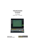
2.1 Names of the Parts and Their Functions
Front Panel
2
POWER ANALYZER
DC - 2 MHz 5 MS/s
CONFIGURATION
RES
SETUP INPUT MEASURE TRIGGER
ET SELECT
ACQ
DISPLAY MATH CURSOR ZOOM
REMOTE indicator
Lit while remote mode is
active via communications.
REMOTE
FILE
MISC
HELP LOCAL
COPY
NULL
CAL
FILTER
FILTER
SHIFT
MENU
ELEMENT
FILTER
1
2
3
FILTER
SINGLE
START
ABORT
4
START/STOP
OBSERVATION TIME
CH 1 CH 3 CH 5 CH 7 VOLTAGE
CH 2 CH 4 CH 6 CH 8 CURRENT
POWER
O
I
LOCAL key
Press this key to switch from remote
mode to local mode so as to enable
key operation.
MISC key
Press this key to set communication setting.
Rear Panel
Serial (RS-232) connector
Used to connect a controller
(personal computer etc.)
using a serial cable.
For information on how to
connect the serial cable,
refer to section 2.3.
IM 253710-11E
2-1
Overview of the Serial Interface
TRIG’ D
ESC
2.2 Serial Interface Functions and Specifications
Receiving Function
It is possible to make the same settings via the serial interface as can be made using the
front panel keys.
Measured/computed data, panel set-up information and error codes can be received.
Sending Function
Measured/computed data can be output.
Panel set-up information and the status byte can be output.
Error codes which have occurred can be output.
Serial Interface Specifications
Electrical characteristics : Complies with EIA-574 Standard (EIA-232 (RS-232) Standard
Connection
for 9 pin)
: Point-to-point
Communications
Synchronization
: Full-duplex
: Start-stop system
Baud rate
Start bit
: 1200, 2400, 4800, 9600, 19200
: 1 bit (fixed)
Data Length
Parity
: 7 or 8 bits
: Even, odd or no parity
Stop Bit
Connector
: 1 or 2 bits
: DELC-J9PAF-13L6 (JAE or equivalent)
Hardware handshaking : User can select whether CA or CB signals will always be True,
or will be used for control.
Software Handshaking : User can select whether to control only transmission or both
transmission and reception using X-on and X-off signals.
X-on (ASCII 11H)
X-off (ASCII 13H)
Receive
: 256 bytes
Switching between Remote and Local Modes
when switched from Local to Remote Mode
Remote mode is activated when the “COMMunicate:REMote ON” command is received
form a controller while local mode is active.
• REMOTE is displayed on.
• All front panel keys except the LOCAL key can no longer be operated any more.
• Settings entered in local mode are retained.
When switched from Remote to Local Mode
Pressing the LOCAL key in remote mode puts the instrument in local mode. However,
this is not possible of Local Lockout (when the “COMMunicate:LOCKout ON” command
is received) has been set by the controller (page 1-6).
Local mode is activated when the “COMMunicate:REMote OFF” command regardless of
Local Lockout.
• The REMOTE indicator is turned off.
• All front panel keys are operative.
• Settings entered in remote mode are retained.
2-2
IM 253710-11E
2.3 Connecting the Serial Interface Cable
When connecting this instrument to a computer, make sure that the handshaking
method, data transmission rate and data format selected for the instrument match those
2
selected for the computer.
For details, refer to the following pages. Also make sure that the correct interface cable
Overview of the Serial Interface
is used.
Connector and Signal Names
5
4
3
2
1
9
8
7
6
2. RD (Received Data) : Data received from personal computer
3. SD (Send Data)
Signal direction...Input
: Data transmitted to a personal computer
5. SG (Signal Ground)
Signal direction...Output
: Ground for signals
7. RS (Request to Send) : Signal used for handshaking when receiving data from a
personal computer
8. CS (Clear to Send)
Signal direction...Output
: Signal used for handshaking when transmitting data to a
personal computer
Signal direction...Input
Pin Nos. 1, 4, 6 and 9 are not used.
9-25 Pin Connector
3 2 7 8
(2) (3)(4) (5)
5
(7)
The number between brackets refer to the pin Nos. of the 25-pin connector.
Signal Direction
The figure below shows the direction of the signals used by the Serial interface.
Computer
IM 253710-11E
RS [Request to send]
7
CS [Clear to send]
8
SD [Send data]
3
RD [Receive data]
2
This
instrument
2-3
2.3 Connecting the Serial Interface Cable
Table of Serial Standard Signals and their
Abbreviation
Pin No.
Description
(9-pin connector) Serial (RS-232)
CCITT
JIS
5
AB (GND)
102
SG
Signal ground
3
BA (TXD)
103
SD
Transmitted data
2
BB (RXD)
104
RD
Received data
7
CA (RTS)
105
RS
Request to send
8
CB (CTS)
106
CS
Clear to send
Signal line connection example
The pin numbers shown are that of 9-pin connectors.
In general, use a cross cable.
• OFF-OFF / XON-XON
PC
SD
RD
RS
CS
SG
2-4
3
2
7
8
5
PZ4000
3
2
7
8
5
SD
RD
RS
CS
SG
• XON-RTS(XON-RS)
PC
SD
RD
RS
CS
SG
3
2
7
8
5
• CTS-RTS(CS-RS)
PZ4000
3
2
7
8
5
SD
RD
RS
CS
SG
PC
SD
RD
RS
CS
SG
3
2
7
8
5
PZ4000
3
2
7
8
5
SD
RD
RS
CS
SG
IM 253710-11E
2.4 Handshaking
To use an serial interface for transferring data between this instrument and a computer, it
is necessary to use certain procedures by mutual agreement to ensure the proper
2
transfer of data. These procedures are called “handshaking.” Various handshaking
systems are available depending on the computer to be used; the same handshaking
Overview of the Serial Interface
system must be used for both the computer and this instrument.
This instrument allows you to choose any handshaking mode from the following four
modes.
Handshake format Descriptions→
Data Sending Control (control
method when sending data to a computer)
Hardware
Software
Handshake
Handshake
No
Sending stops Sending stops
handshake
when X-off is when CB(CTS) is
received, and False, and
sending is
sending is
resumed
resumed when CB
when X-on is is True.
received.
Handshake
Method
The menu of
this instrument
OFF-OFF
NO-NO
XON-XON
XON-XON
XON-RS
XON-RTS
CS-RS
CTS-RTS
Data Receiving Control (control
method when receiving data from a computer)
Hardware
Software
Handshake
Handshake
No
X-off is sent
CA (RTS) is set to
handshake
when received False when
data buffer
received data buffer
becomes 3/4- is only 3/4-full, and
full, and X-on is is set to True when
sent when the received data buffer
received data is only 1/4-full.
buffer is only
1/4-full.
1 OFF-OFF
• Transmission data control
There is no handshake status between the instrument and host computer. The X-OFF
and X-ON signal from the host computer is processed as data, and the CS signal is
ignored.
• Reception data control
There is no handshake status between the recorder and host computer. When the
recorder reception buffer becomes full, the excess data is discarded. RS = True (fixed)
2 XON-XON
• Transmission data control
A software handshake status is established between the instrument and host
computer. The instrument will stop a data transmission when an X-OFF signal is
received from the host computer, and will resume transmission when the next X-ON
signal is received. A CS signal from the host computer is ignored.
• Reception data control
A software handshake status is established between the instrument and host
computer. When the intstruments reception buffer vacancy reaches 64bytes, the XOFF signal will be sent to the host computer. When the reception buffer vacancy
reaches 192 bytes, the X-ON signal will be sent. RS = True (fixed)
IM 253710-11E
2-5
2.4 Handshaking
3 XON-RS
• Transmission data control
A software handshake status is established between the instrument and host
computer. The instrument will stop a data transmission when an X-OFF signal is
received from the host computer, and will resume transmission when the next X-ON
signal is received. A CS signal from the host computer is ignored.
• Reception data control
A hardware handshake status is established between the instrument and host
computer. When the intstruments reception buffer vacancy reaches 64bytes, an “RS =
False” status will be established. When the reception buffer vacancy reaches 192
bytes, an “RS = True” status will be established.
4 CS-RS
• Transmission data control
A software handshake status is established between the instrument and host
computer. The instrument will stop a data transmission if a “CS = False” status is
established, and will resume the transmission shen a “CS = True” status is
established. The X-OFF and X-ON signals from the host computer are processed as
data.
• Reception data control
A hardware handshake status is established between the instrument and host
computer. When the intstruments reception buffer vacancy reaches 64bytes, an “RS =
False” status will be established. When the reception buffer vacancy reaches 192
bytes, an “RS = True” status will be established.
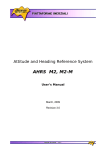
Precautions Regarding Data Receiving Control
When handshaking is used to control the reception of data, data may still be sent from
the computer even if the free space in the receive buffer drops below 64 bytes. In this
case, after the receive buffer becomes full, the excess data will be lost, whether
handshaking is in effect or not. Data storage to the buffer will begin again when there is
free space in the buffer.
256 bytes
When handshaking is in use,
reception of data will stop when the
free space in the buffer drops to 64
bytes since data cannot be passed to
Free, 64 bytes the main program fast enough to
keep up with the transmission.
Used
Used
Free, 192 bytes
Used
After reception of data stops, data
continues to be passed to the internal
program. Reception of data starts
again when the free space in the
buffer increases to 192 bytes.
Whether handshaking is in use or not,
if the buffer becomes full, any
additional data received is no longer
stored and is lost.
Data Receiving Control using Handshaking
Note
It is necessary to create a host computer program which prevents the buffers of both the
intrument and the computer from becoming full.
2-6
IM 253710-11E
2.5 Matching the Data Format
The serial interface of this instrument performs communications using start-stop
synchronization. In start-stop synchronization, one character is transmitted at a time.
2
Level returns to idle
state (dotted line)
until the start bit of
the next item of data
(solid line).
1 character
Circuit idle state
Data bit
(7 or 8 bits)
Stop bit
Start bit
IM 253710-11E
Parity bit
Even, odd or none
1
1 or 2 bits
2
2-7
Overview of the Serial Interface
Each character consists of a start bit, data bits, a parity bit and a stop bit. Refer to the
figure below.
2.6 Setting up this Instrument
Before You Begin
When using the controller to set the items which can be set locally using the keys on the
instrument, or when outputting the setup information or the waveform data to the
controller, set the following items.
Baud rate
Select from the following choices.
1200, 2400, 4800, 9600, 19200
Data format
Select the combination of the data length and the stop bit from the following choices.
8-NO-1, 7-EVEN-1, 7-ODD-1, 7-NO-2
Handshaking method
Select the transmit data control and the receive data control from the following choices.
NO-NO, XON-XON, XON-RTS, CTS-RTS
Terminator
Select from the following choices. The terminator used when sending the data from this
instrument is selected on the menu. Use either “LF” or “CR+LF” for the terminator in
receiving the data.
CR, LF, CR+LF
Operating Procedure
Displaying the Serial (RS-232) menu
1.
2.
Press the MISC key.
Press the “GP-IB/RS232” soft key.
3. Press the “Comm Device” soft key to select “RS232.”
Selecting the baud rate, the data format and etc.
4.
Press the “BaudRate” (baud rate), “Format” (data format), “Rx-Tx” (handshaking
method), and the “Terminator” (terminator) soft keys individually, and set each item.
Step 1, 2
2-8
Step 3, 4
IM 253710-11E
3.1 Messages
Chapter 3 Before Programming
3.1 Messages
Blocks of message data are transferred between the
controller and this instrument during communications.
Messages sent from the controller to this instrument
response messages.
If a program message contains a message unit, i.e. a
command which requests a response, this instrument
returns a response message. A single response
,
<Program header>
Space
<Program data>
3
<Program header>
A program header is used to indicate the command
type. For details, refer to page 3-3.
message is always returned in reply to a program
message.
<Program data>
Program Messages
data must be separated from the header by a space
(ASCII code “20H”). If multiple items of program data
The format of a program message is shown below.
;
<Program message unit>
<PMT>
If certain conditions are required for the execution of a
command, program data must be added. Program
are included, they must be separated by a “,”
(comma). For details, refer to page 3-5.
Example
:TRIGger:MODE AUTO<PMT>
<Program message unit>
A program message consists of one or more program
message units; each unit corresponds to one
command. This instrument executes commands one
Header
Response Messages
The format of a response message is shown below.
by one according to the order in which they are
received.
Program message units are delimited by a “;”.
For a description of the format of the program
message unit, refer to the explanation given further
below.
Example
:TRIGger:MODE AUTO;SOURCE 1<PMT>
Unit
Unit
Data
;
<Response message unit>
<RMT>
<Response message units>
A response message consists of one or more
response message units: each response message unit
corresponds to one response.
Response message units are delimited by a “;”.
For the response message format, refer to the next
page.
<PMT>
PMT is a terminator used to terminate each program
Example
:TRIGger:MODE AUTO;SOURCE 1<RMT>
message. The following three types of terminator are
available.
NL (New Line) : Same as LF (Line Feed). ASCII code
“0AH” is used.
^END
: END message defined in IEEE488.1.
(EOI signal)
Unit
Unit
<RMT>
RMT is the terminator used for every response
message. Only one type of response message is
available; NL^END.
(The data byte sent with an END
message will be the final item of the
NL^END
program message unit.)
: NL with an END message attached
(NL is not included in the program
message unit.)
IM 253710-11E
3-1
Before Programming
are called program messages, and messages sent
back from this instrument to the controller are called
Program message unit format
The format of a program message unit is shown below.
3.1 Messages
Response message unit format
• If a program message of more than one unit is sent
The format of a program message unit is shown below.
,
<Response header>
Space
<Response data>
<Response header>
A response header sometimes precedes the response
data. Response data must be separated from the
header by a space. For details, refer to page 3-4.
<Response data>
Response data is used to define a response. If
multiple items of response data are used, they must be
separated by a “,” (comma). For details, refer to page
3-5.
Example
100.00E-03<RMT>
:DISPLAY:FORMAT WAVE<RMT>
Data
Header
Data
If a program message contains more than one query,
responses are made in the same order as the queries.
Normally, each query returns only one response
message unit, but there are some queries which return
and some of the units are incomplete, this
instrument receives program message units which
the instrument thinks complete and attempts to
execute them. However, these attempts may not
always be successful and a response may not
always be returned, even if the program message
contains queries.
Deadlock
This instrument has a buffer memory in which both
program and response messages of 1024 bytes or
more can be stored. (The number of bytes available
will vary depending on the operating state of the
instrument.) If the transmission and reception buffer
memories become full at the same time, the instrument
will not be able to continue the communication
operation. This state is called deadlock. In this case,
operation can be resumed by discarding the response
message.
No dead lock will occur, if the size of the program
message including the PMT is kept below 1024 bytes.
Furthermore, no deadlock will occur if the program
message does not contain a query.
more than one response message unit. The first
response message unit always responds to the first
query, but it is not always true that the ‘n’ th unit
always responds to the ‘n’ th query. Therefore, if you
want to make sure that a response is made to each
query, the program message must be divided up into
individual messages.
Points to Note concerning Message Transmission
• It is always possible to send a program message if
the previous message which was sent did not
contain any queries.
• If the previous message contained a query, it is not
possible to send another program message until a
response message has been received. An error will
occur if a program message is sent before a
response message has been received in its entirety.
A response message which has not been received
will be discarded.
• If an attempt is made by the controller to receive a
response message, even if there it no response
message, an error will occur. An error will also
occur if the controller makes an attempt to receive a
response message before transmission of a
program message has been completed.
3-2
IM 253710-11E
3.2 Commands
3.2 Commands
When Concatenating Commands
There are three types of command (program header)
which can be sent from the controller to this
Command Group
A command group is a group of commands which have
instrument. They differ in the format of their program
headers.
the same compound header. A command group may
contain sub-groups.
They are
Example Commands relating to acquisition settings
• Common command header
• Compound header
:ACQuire?
:ACQuire:DIVision
:ACQuire:RLENgth
:ACQuire:TBASe
Common Command Header
Commands defined in IEEE 488.2-1987 are called
common commands. The header format of a common
command is shown below. An asterisk (*) must
always be attached to the beginning of a command.
<Mnemonic>
*
Before Programming
• Simple header
3
When Concatenating Commands of the Same
Group
This instrument stores the hierarchical level of the
command which is currently being executed, and
performs analysis on the assumption that the next
command to be sent will also belong to the same level.
Therefore, it is possible to omit the header if the
?
An example of a common command
*CLS
commands belong to the same group.
Example :ACQuire:DIVision ON;TBASE INTernal
Compound Header
Commands designed to be used only with this
instrument are classified and arranged in a hierarchy
according to their function. The format of a compound
header is illustrated below. A colon (:) must be used
when specifying a lower-level header.
:
:
<Mnemonic>
?
<PMT>
When Concatenating Commands of Different
Groups
A colon (:) must be included before the header of a
command, if the command does not belong to the
same group as the preceding command.
Example :ACQuire:DIVision ON;:DISPlay:FORMat
NUMeric<PMT>
An example of a compound header
:ACQuire:DIVision
When you type in a simple header after another
command, you must include a colon (:) before the
Simple Header
These commands (headers) are functionally
independent of each other and are not arranged
hierarchically. The format of a simple header is shown
below.
:
<Mnemonic>
When Concatenating Simple Headers
?
simple header.
Example :ACQuire:DIVision ON;:STARt<PMT>
When Concatenating Common Commands
Common commands defined in IEEE 488.2-1987 are
An example of a simple header
independent of hierarchical level. Thus, it is not
necessary to add a colon (:) before a common
:STARt
command.
Note
Example :ACQuire:DIVision ON;*CLS;TBASe
A mnemonic is a character string made up of alphanumeric
characters.
IM 253710-11E
INTernal<PMT>
3-3
3.2 Commands
When Separating Commands with <PMT>
• Any part of a command enclosed by [ ] can be
If a terminator is used to separate two commands,
each command is a separate message. Therefore, the
omitted.
Example
common header must be typed in for each command
even when commands of the same command group
“TRIGger[:SIMPLle]:LEVel” can be written as
“TRIG:LEV”.
are being concatenated.
Example :ACQuire:DIVision ON<PMT>:ACQuire:
TBASe INTernal<PMT>
• However, a part enclosed by [ ] cannot be omitted if
is located at the end of an upper-level query.
Example
“TRIGger?” and “TRIGger:SIMPle?” belong to
different upper-level query levels.
Upper-level Query
An upper-level query is a compound header to which a
question mark is appended. Execution of an upperlevel query allows all a group’s settings to be output at
once. Some query groups comprising more than three
hierarchical levels can output all their lower level
settings.
Example :TIMebase?<PMT>→:TIMEBASE:OBSERVE
100.00E-03;SRATE 1.000000E+06
In reply to a query, a response can be returned as a
program message to this instrument. Transmitting a
response can restore the settings made when the
query was executed. However, some upper-level
queries will not return set-up data which is not currently
in use. Note that not all a group’s information will
necessarily be sent out as a response.
Header Interpretation Rules
This instrument interprets the header received
according to the following rules.
• Mnemonics are not case sensitive.
Example
“CURSor” can also be written as “cursor” or
“Cursor”.
• The lower-case part of a header can be omitted.
Example
“CURSor” can also be written as “CURSO” or “CURS”.
• If the header ends with a question mark, the
command is a query. It is not possible to omit the
question mark.
Example
“CURSor?” cannot be abbreviated to anything shorter
than “CURS?”.
• If the “x” at the end of a mnemonic is omitted, it is
assumed to be “1”.
Example
If “CHANnel<x>” is written as “CHAN”, this represents
“CHANnel1”.
3-4
IM 253710-11E
3.3 Response/3.4 Data
3.3 Response
3.4 Data
On receiving a query from the controller, this
instrument returns a response message to the
Data
A data section comes after the header. A space must
controller. A response message is sent in one of the
following two forms.
be included between the header and the data. The
data contains conditions and values. Data is classified
as below.
• Response consisting of a header and data
to the query, which is then returned.
Example :DISPlay:FORMat?<PMT>→:DISPLAY:
FORMAT WAVE<RMT>
Description
<Decimal>
Value expressed as a decimal number
(Example: Number of displayed digits for numerical data
→SETup:RESolution 5)
<Voltage><Current>
Physical value
<Time><Frequency>
(Example: Waveform observation time
<Register>
Register value expressed as either binary, octal, decimal
→TIMebase:OBServe 100M)
or hexadecimal
• Response consisting of data only
If the query cannot be used as a program message
unless changes are made to it (i.e. it is a query-only
command), no header is attached and only the data
is returned. Some query-only cmands can be
returned after a header is attached to them.
Example :CHANnel1:TYPE?<PMT>→VOLTAGE<RMT>
(Example: Extended event register value
→STATus:EESE #HFE)
<Character data>
Specified character string (mnemonic). Can be selected
from { }
(Example: Measurement mode
→SETup[:MODE] {NORMal|HARMonics})
<Boolean>
Indicates ON/OFF. Set to ON, OFF or value
(Example: CH2 waveform display ON
→CHANnel2:DISPlay ON)
<Character string data> Arbitrary character string
(Example: Waveform label of CH1
→CHANnel:LABel "CH1")
When returning a response without a header
It is possible to remove the header from a response
consisting of a header and data. The
“COMMunicate:HEADer” command is used to do this.
<Filename>
Gives the name of a file.
(Example: Name of file to be saved
→FILE:SAVE:WAVE[:EXECute] "CASE1")
<Block data>
Arbitrary 8-bit data
(Example: Response to acquired waveform data
→#800000010ABCDEFGHIJ)
Abbreviated form
Normally, the lower-case part is removed from a
response header before the response is returned to
<Decimal>
<Decimal> indicates a value expressed as a decimal
the controller. Naturally, the full form of the header can
also be used. For this, the “COMMunicate:VERBose”
number, as shown in the table below. Decimal values
are given in the NR form specified in ANSI X3. 42-
command is used. The part enclosed by [ ] is also
omitted in the abbreviated form.
1975.
Symbol
Description
Example
<NR1>
Integer
125
<NR2>
Fixed point number
125.0
<NR3>
Floating point number
125.0E+0
<NRf>
Any of the forms <NR1> E4 to <NR3> is allowed.
-1
+1000
–.90
+001.
–9E–1
+.1E4
Decimal values which are sent from the controller to
this instrument can be sent in any of the forms to
<NR3>. In this case, <NRf> appears.
For response messages which are returned from this
instrument to the controller, the form (<NR1> to <NR3>
to be used) is determined by the query. The same
form is used, irrespective of whether the value is large
or small.
In the case of <NR3>, the “+” after the “E” can be
omitted, but the “–” cannot.
If a value outside the setting range is entered, the
value will be normalized so that it is just inside the
range.
If the value has more than the significant number of
digits, the value will be rounded.
IM 253710-11E
3-5
3
Before Programming
If the query can be used as a program message
without any change, a command header is attached
Data
3.4 Data
<Voltage>, <Current>, <Time>, <Frequency>
<Voltage>, <Current>, <Time> and <Frequency>
<Register>
<Register> indicates an integer, and can be expressed
indicate decimal values which have physical
significance. <Multiplier> or <Unit> can be attached to
in hexadecimal, octal or binary as well as as a decimal
number. <Register> is used when each bit of a value
<NRf>. They can be entered in any of the following
forms.
has a particular meaning. <Register> is expressed in
one of the following forms.
Form
Example
Form
Example
<NRf><Multiplier><Unit>
5MV
<NRf>
1
<NRf><Unit>
5E-3V
#H<Hexadecimal value made up of the digits 0 to 9, and A to F>
#H0F
<NRf><Multiplier>
5M
#Q<Octal value made up of the digits 0 to 7>
#Q777
<NRf>
5E-3
#B<Binary value made up of the digits 0 and 1>
#B001100
<Multiplier>
Multipliers which can be used are shown below.
<Register> is not case sensitive.
Response messages are always expressed as <NR1>.
Symbol
Word
Description
EX
Exa
1018
PE
Peta
1015
T
Tera
1012
G
Giga
109
MA
Mega
106
K
Kilo
103
M
Mili
10-3
U
Micro
10-6
For interpretation rules, refer to “Header Interpretation
Rules” on page 3-4.
N
Nano
10-9
Form
Example
P
Pico
10-12
{NORMal|HARMonics}
NORMAL
F
Femto
10-15
<Character Data>
<Character data> is a specified string of character data
(a mnemonic). It is mainly used to indicate options,
and is chosen from the character strings given in { }.
As with a header, the “COMMunicate:VERBose”
<Unit>
Units which can be used are shown below.
Symbol
Word
Description
V
Volt
Voltage
A
Ampere
Current
S
Second
Time
HZ
Hertz
Frequency
MHZ
Megahertz
Frequency
command can be used to return a response message
in its full form. Alternatively, the abbreviated form can
be used.
The “COMMunicate:HEADer” command does not affect
<character data>.
<Multiplier> and <Unit> are not case sensitive.
<Boolean>
<Boolean> is data which indicates ON or OFF, and is
“U” is used to indicate “µ”.
Form
Example
{ON|OFF|<NRf>}
ON
“MA” is used for Mega (M) to distinguish it from Mili,
expressed in one of the following forms.
OFF
1
0
0
except for in the case of Megahertz, which is
expressed as “MHZ”. Hence, it is not permissible to use
When <Boolean> is expressed in <NRf> form, OFF is
selected if the rounded integer value is “0” and ON is
“M” (Mili) for Hertz.
selected if the rounded integer is “Not 0”.
A response message is always “1” if the value is ON
If both <Multiplier> and <Unit> are omitted, the default
unit will be used.
Response messages are always expressed in <NR3>
form. Neither <Multiplier> nor <Unit> is used,
therefore the default unit is used.
and “0” if it is OFF.
<Character String Data>
<Character string data> is not a specified character
string like <Character data>. It is an arbitrary
character string. A character string must be enclosed
in single quotation marks (') or double quotation marks
(").
Form
Example
<Character string data>
"ABC" "IEEE488.2-1987"
Response messages are always enclosed in double
quotation marks.
3-6
IM 253710-11E
3.5 Synchronization with the Controller
If a character string contains a double quotation mark
("), the double quotation mark will be replaced by two
concatenated double quotation marks ("""). This rule
3.5 Synchronization with the
Controller
Overlap Commands and Sequential Commands
There are two kinds of command; overlap commands
and sequential commands. Execution of an overlap
<Character string data> is an arbitrary character string,
command may start before execution of the previously
sent command is completed.
therefore this instrument assumes that the remaining
program message units are part of the character string
The [CHANnel1:VOLTage:RANGe] command, for
example, is a sequential command. Assume that you
if no single (') or double quotation mark (") is
encountered. As a result, no error will be detected if a
set a new voltage range value and immediately
request return of the new value, as follows:
quotation mark is omitted.
:CHANnel1:VOLTage:RANGe 200V;RANGe?<PMT>
In this case, the oscilloscope always returns the
<Filename>
Gives the name of a file. The format is as follows.
newest setting (“200V”). This is because it always
completes processing of the current sequential
Form
Example
{<NRf>|<Character data>|<Character string>}
1
command (in this case, “RANGe 200V”) before moving
on to the next command (“RANGe?”).
CASE
"CASE"
If you input an <NRf> value, the system converts the
value (after rounding to the nearest integer) to the
corresponding 8-character ASCII string. (If you set the
value to 1, the name becomes "00000001".) Note that
negative values are not allowed.
If you enter a <character data> or <character string>
argument that is longer than eight characters, only the
first eight characters are used.
Response messages always return filenames as
<character string> arguments.
<Block data>
<Block data> is arbitrary 8-bit data. <Block data> is
only used for response messages. Response
In contrast, assume that you begin a file load and then
immediately query the voltage range value:
:FILE:LOAD:SETup "FILE1";:CHANnel1:VOLTage:
RANGe?
Because “FILE:LOAD:SETup” is an overlapped
command, the oscilloscope will advance to the
“CHANNel1:VOLTage:RANGe?” command before it
finishes the load. The returned voltage range value
will not show the newest setting, but will rather show
the setting in use before the setup was changed.
Obviously, use of overlapped commands may in some
cases produce inappropriate results. Where
necessary, you can avoid such problems as described
below.
messages are expressed in the following form.
Form
Example
#N<N-digit decimal value><Data byte string>
#800000010ABCDEFGHIJ
Synchronization with an Overlap Command
Using the *WAI command
#N
Indicates that the data is <Block data>. “N” is an ASCII
The *WAI command causes the commands which
follow it to wait until an overlap command has been
character string number (digits) which indicates the
number of data bytes that follow.
executed.
Example
:COMMunicate:OPSE #0040;:FILE:LOAD:
<N-digits decimal value>
SETup "FILE1";*WAI;:CHANnel1:VOLTage:
Indicates the number of bytes of data. (Example:
00000010 = 10 bytes)
<PMT>
<Data byte string>
The “COMMunicate:OPSE” command is used to
designate which commands are to be subject to the
*WAI command. In the above example, only auto set-
The actual data. (Example: ABCDEFGHIJ)
up is designated.
Since a *WAI command is executed just before
Data is comprised of 8-bit values (0 to 255). This
means that the ASCII code “0AH”, which stands for
“CHANnel1:VOLTage:RANGe?”,
“CHANnel1:VOLTage:RANGe?” will not be executed until
“NL”, can also be a code used for data. Hence, care
must be taken when programming the controller.
auto set-up has been completed.
IM 253710-11E
3-7
3
Before Programming
also applies to a single quotation mark within a
character string.
3.5 Synchronization with the Controller
Using the COMMunicate:OVERlap command
Using the *OPC? query
The “COMMunicate:OVERlap” command is used to
enable or disable overlap operation.
The *OPC? query generates a response when an
overlap operation has been completed.
Example
Example
:COMMunicate:OVERlap #HFFBF;:FILE:LOAD:SETup
:COMMunicate:OPSE #H0040;:FILE:LOAD:SETup
"FILE1";:CHANnel1:VOLTage:VOLTage:RANGe?<PMT>
"FILE1";*OPC?<PMT>
The “COMMunicate:OVERlap #HFFBF” command
(Response to *OPC? is decoded.)
disables overlapped operation of the medium access
command, while enabling all other overlap-type
:CHANnel1:VOLTage:RANGe?<PMT>
operations. The oscilloscope will therefore handle
“FILE:LOAD:SETup” s a sequential command,
designate which commands are to be subject to the
*OPC? command. In the above example, only medium
ensuring that the “CHANnel1:VOLTage:RANGe?”
command (in the above example) will not execute until
access commands are designated.
Since *OPC? does not generate a response until an
file loading is completed.
overlap operation is completed, file loading will have
been completed when a response to *OPC? is read.
Using the *OPC command
The *OPC command causes the OPC bit (bit 0) of the
Note
standard event register (page 5-3) to be set to “1”
when an overlap operation has been completed.
The “COMMunicate:OPSE” command is used to
Most commands are sequential commands. Commands used in
Chapter 4 are sequential commands unless otherwise specified.
Example
:COMMunicate:OPSE #H0040;*ESE 1;*ESR?;
*SRE 32;:FILE:LOAD:SETup "FILE1";*OPC<PMT>
(Response to *ESR? is decoded.)
(Service request is awaited.)
CHANnel1:VOLTage:VDIV:VALue?<PMT>
The “COMMunicate:OPSE” command is used to
designate which commands are to be subject to the
*OPC command. In the above example, only medium
access commands are designated.
*ESE 1 and *SRE 32 stipulate that a service request is
generated only when the OPC bit is set to “1”.
*ESR? is used to clear the standard event register.
In the above example, “CHANnel1:VOLTage:RANGe?”
will not be executed until a service request is
generated.
Synchronization with Non-Overlap Commands
Synchronization is sometimes required for reasons
other than communications-related reasons, such as
the activation of a trigger, even if a sequential
command is used.
As an example, the following message is properly used
to query waveform data obtained by a “single start”
operation:
SSTart;WAVeform:SEND?<PMT>
But sending this message (executing this command)
before a single-start reading has been registered may
result in a command error.
In this case, synchronization with the time at which
acquisition is completed must be accomplished, as
shown next.
Using STATus:CONDition? query
A “STATus:CONDition?” query is used to make an
query about the contents of the condition register
(page 5-4). It is possible to judge whether acquisition
is in progress or not by reading bit 0 of the condition
register. Bit 0 is “1” if acquisition is in progress, and “0”
if acquisition is stopped.
Example
:SSTart<PMT>
:STATus:CONDition?<PMT>
(Returns to the previous status if bit 0 is found to be “1”
when the response is decoded.)
:WAVeform:SEND?<PMT>
A “WAVeform:SEND?” query will not be executed until bit
0 of the condition register has been set to “0”.
3-8
IM 253710-11E
3.5 Synchronization with the Controller
Using the extended event register
Changes in the condition register are reflected in the
extended event register (page 5-4).
Example
:STATus:FILTer1 FALL;:STATus:EESE 1;EESR?;
*SRE 8;:SSTart<PMT>
3
Before Programming
(Response to STATus:EESR? is decoded.)
(Service request is awaited.)
:WAVeform:SEND?<PMT>
The “STATus:FILTer1 FALL” command sets the
transition filter such that Bit 0 (FILTer1) of the
Extended Event Register sets to 1 when Bit 0 of the
Condition Register changes from 1 to 0.
“STATus:EESE 1” is a command used only to reflect
the status of bit 0 of the extended event register in the
status byte.
“STATus:EESR?” is used to clear the extended event
register.
The “*SRE” command is used to generate a service
request caused solely by the extended event register.
“WAVeform:SEND?” will not be executed until a service
request is generated.
Using the COMMunicate:WAIT command
The “COMMunicate:WAIT” command halts
communications until a specific event is generated.
Example
:STATus:FILTer1 FALL;:STATus:EESR?;:
SSTart<PMT>
(Response to STATus:EESR? is decoded.)
:COMMunicate:WAIT 1;:WAVeform:SEND?<PMT>
For a description of “STATus:FILTer1 FALL” and
“STATus:EESR?”, refer to “Using the extended event
register” on this page.
“COMMunicate:WAIT 1” means that communications is
halted until bit 0 of the extended event register is set to
“1”.
IM 253710-11E
3-9
4.1 Command Listing
Chapter 4 Commands
4.1 Command Listing
Command
ABORt Group
Function
Page
:ABORt
Aborts data acquisition.
4-11
Queries all settings related to data acquisition.
Sets whether or not to divide the record length or queries the current setting.
Sets the record length or queries the current setting.
Sets the sampling block or queries the current setting.
4-11
4-11
4-11
4-11
Queries all settings related to the vertical axis of each channel.
Queries all settings related to the current input channel.
Sets the current range of the current input channel or queries the current setting.
Sets the current sensor’s scaling constant of the current input channel or queries the
current setting.
4-13
4-13
4-13
ACQuire Group
:ACQuire?
:ACQuire:DIVision
:ACQuire:RLENgth
:ACQuire:TBASe
:CHANnel<x>:CURRent?
:CHANnel<x>:CURRent:RANGe
:CHANnel<x>:CURRent:SRATio
:CHANnel<x>:CURRent:TERMinal
:CHANnel<x>:DISPlay
:CHANnel<x>:LABel
:CHANnel<x>:POSition
:CHANnel<x>:SPEed?
:CHANnel<x>:SPEed:FRANge
:CHANnel<x>:SPEed:RANGe
:CHANnel<x>:SPEed:TYPE
:CHANnel<x>:TORQue?
:CHANnel<x>:TORQue:RANGe
:CHANnel<x>:TYPE?
:CHANnel<x>:VOLTage?
:CHANnel<x>:VOLTage:RANGe
:CHANnel<x>:VZoom
4-13
Sets the current measurement terminal of the current input channel or queries the current
setting.
4-13
Turns ON/OFF the waveform display of each channel or queries the current setting.
4-13
Sets the waveform label of each channel or queries the current setting.
4-14
Sets the vertical position (the GND position) of each channel or queries the current setting. 4-14
Queries all settings related to the revolution sensor signal input channel.
4-14
Sets the frequency range of the revolution sensor signal input channel (pulse input) or
queries the current setting.
4-14
Sets the input range of the revolution sensor signal input channel or queries the current
setting.
4-14
Sets the input type of the revolution sensor signal input channel or queries the current
setting.
4-15
Queries all settings related to the torque meter signal input channel.
4-15
Sets the input range of the torque meter signal input channel or queries the current setting. 4-15
Queries the input type of each channel.
4-15
Queries all settings related to the voltage input channel.
4-15
Sets the voltage range of the voltage input channel or queries the current setting.
4-15
Sets the vertical zoom factor or queries the current setting.
4-15
COMMunicate Group
:COMMunicate?
:COMMunicate:HEADer
:COMMunicate:LOCKout
:COMMunicate:OPSE
:COMMunicate:OPSR?
:COMMunicate:OVERlap
:COMMunicate:REMote
:COMMunicate:STATus?
:COMMunicate:VERBose
:COMMunicate:WAIT
:COMMunicate:WAIT?
Queries all settings related to communications.
Sets whether or not to attach headers to response data or queries the current setting.
Sets/releases local lockout.
Sets the overlap commands for *OPC, *OPC?, and *WAI or queries the current setting.
Queries the operation pending status register.
Sets the commands to permit overlap operation or queries the current setting.
Switches between remote and local.
Queries the line-specific status.
Sets whether to use the full or abbreviated form for response data or queries the current
setting.
Waits for an extended event to occur.
Generates a response when one of the specified extended events occurs.
4-16
4-16
4-16
4-17
4-17
4-17
4-17
4-17
4-17
4-17
4-17
CURSor Group
Queries all settings related to cursor measurements.
Queries all settings related to the H cursor.
:CURSor:HORizontal:DY?
Queries the Y-axis value between the H cursors.
:CURSor:HORizontal:POSition<x> Sets the H cursor position or queries the current setting.
:CURSor?
:CURSor:HORizontal?
IM 253710-11E
4-19
4-19
4-19
4-19
4-1
Commands
CHANnel Group
:CHANnel<x>?
4
4.1 Command Listing
Command
:CURSor:HORizontal:TRACe
:CURSor:HORizontal:Y<x>?
:CURSor:MARKer?
:CURSor:MARKer:DX?
:CURSor:MARKer:DY?
:CURSor:MARKer:FFT<x>
:CURSor:MARKer:JUMP
Function
Sets the waveform on which to place the H cursor or queries the current setting.
Queries the Y-axis value of the H cursor.
Queries all settings related to the marker.
Queries the X-axis value between the marker.
Queries the Y-axis value between the marker.
Sets the X-axis value of the marker position for the FFT result or queries the current
setting.
Jumps to the zoomed waveform of the marker.
Page
4-19
4-20
4-20
4-20
4-20
4-20
4-20
:CURSor:MARKer:PERDt?(1 PER Delta T)
:CURSor:MARKer:POSition<x>
:CURSor:MARKer:TRACe<x>
:CURSor:MARKer:X<x>?
:CURSor:MARKer:Y<x>?
:CURSor:[TYPE]
:CURSor:VERTical?
:CURSor:VERTical:DX?
:CURSor:VERTical:FFT<x>
:CURSor:VERTical:PERDt?
:CURSor:VERTical:POSition<x>
:CURSor:VERTical:TRACe
:CURSor:VERTical:X<x>?
:CURSor:XY?
:CURSor:XY:DX?
:CURSor:XY:POSition<x>
:CURSor:XY:TRACe?
:CURSor:XY:X<x>?
Queries the 1/∆ value of the horizontal axis between the marker.
Sets the marker position or queries the current setting.
Sets the waveform on which to place the marker or queries the current setting.
Queries the X-axis value of the marker position.
Queries the Y-axis value of the marker position.
Sets the cursor type or queries the current setting.
Queries all settings related to the V cursor.
Queries the X-axis value between the V cursors.
Sets the V cursor position with respect to the FFT result.
Queries the 1/∆ value of the horizontal axis between the V cursors.
Sets the V cursor position or queries the current setting.
Sets the waveform on which to place the V cursor or queries the current setting.
Queries the X-axis value of the V cursor position.
Queries all settings related to the XY cursor.
Queries the X-axis value between the XY cursors.
Sets the XY cursor position or queries the current setting.
Queries the waveform on which the XY cursor is placed.
Queries the X-axis value of the XY cursor position.
4-20
4-21
4-21
4-21
4-21
4-21
4-21
4-21
4-21
4-22
4-22
4-22
4-22
4-22
4-22
4-22
4-22
4-22
DISPlay Group
Queries all settings related to the screen display.
Queries all settings related to the bar graph display.
:DISPlay:BAR:CURSor<x>
Sets the marker position (harmonic order) on the bar graph display or queries the current
setting.
:DISPlay:BAR:ITEM<x>
Sets the bar graph display items (function, element) or queries the current setting.
:DISPlay:BAR:ORDer
Sets the start and end harmonic orders of the bar graph display or queries the current
setting.
:DISPlay:DATE
Turns ON/OFF the date and time displays or queries the current setting.
:DISPlay:FORMat
Sets the display format or queries the current setting.
:DISPlay:NUMeric?
Queries all settings related to the numerical display.
:DISPlay[:NUMeric]:HARMonics? Queries all settings related to the numerical display during harmonic measurement.
:DISPlay?
:DISPlay:BAR?
4-25
4-25
4-25
4-25
4-25
4-26
4-26
4-26
4-26
:DISPlay[:NUMeric]:HARMonics:IAMount
Sets the numerical display format during harmonic measurement or queries the current
setting.
4-26
:DISPlay[:NUMeric]:HARMonics:ICURsor
Sets the cursor position of the numerical display during harmonic measurement or queries
the current setting.
4-27
:DISPlay[:NUMeric]:HARMonics:ITEM<x>
Sets the numerical displayed items during harmonic measurement or queries the current
setting.
4-27
:DISPlay[:NUMeric]:HARMonics:LCURsor
Sets the cursor position on the list display during harmonic measurement or queries the
current setting.
4-27
:DISPlay[:NUMeric]:HARMonics:LIST<x>
Sets the list display items during harmonic measurement or queries the current setting.
4-27
:DISPlay[:NUMeric]:HARMonics:PRESet
Sets the numerical display items to a preset pattern during harmonic measurement.
4-2
4-27
IM 253710-11E
4.1 Command Listing
Command
:DISPlay[:NUMeric]:NORMal?
Function
Queries all settings related to the numerical display during normal measurement.
Page
4-27
:DISPlay[:NUMeric]:NORMal:FCURsor
Sets the cursor position of the numerical display (All display) during normal measurement
or queries the current setting.
4-28
:DISPlay[:NUMeric]:NORMal:IAMount
Sets the numerical display format during normal measurement or queries the current
setting.
4-28
:DISPlay[:NUMeric]:NORMal:ICURsor
Sets the cursor position of the numerical display (split display) during normal measurement
or queries the current setting.
4-28
:DISPlay[:NUMeric]:NORMal:ITEM<x>
4
4-28
:DISPlay[:NUMeric]:NORMal:PRESet
:DISPlay:VECTor?
:DISPlay:VECTor:IMAG
:DISPlay:VECTor:NUMeric
:DISPlay:VECTor:UMAG
:DISPlay:WAVE?
Sets the numerical display items to a preset pattern during normal measurement.
Queries all settings related to the vector display.
Sets the zoom factor of the current display during vector display or queries the current
setting.
Turns ON/OFF the numerical data display during vector display or queries the current
setting.
Sets the zoom factor of the voltage display during vector display or queries the current
setting.
Queries all settings related to the waveform display.
4-28
4-28
4-28
4-29
4-29
4-29
:DISPlay:WAVE:{CHANnel<x>|MATH<x>}
:DISPlay:WAVE:FORMat
:DISPlay:WAVE:GRATicule
:DISPlay:WAVE:INTerpolate
:DISPlay:WAVE:MAPPing?
Turns ON/OFF the channel/computed waveform display or queries the current setting.
Sets the display format of the waveform or queries the current setting.
Sets the graticule type (grid) or queries the current setting.
Sets the interpolation method of the waveform or queries the current setting.
Queries all settings related to the waveform mapping to the split screen.
4-29
4-29
4-29
4-29
4-29
:DISPlay:WAVE:MAPPing:{CHANnel<x>|MATH<x>}
:DISPlay:WAVE:MAPPing[:MODE]
:DISPlay:WAVE:SVALue
:DISPlay:WAVE:TLABel
:DISPlay:XY?
:DISPlay:XY:FFT
:DISPlay:XY:INTerpolate
:DISPlay:XY:POSition
:DISPlay:XY:XTRace
Sets the {channel waveform|MATH waveform} mapping to the split screen or queries the
current setting.
Sets the waveform mapping method for the split screen or queries the current setting.
Turns ON/OFF the scale value display or queries the current setting.
Turns ON/OFF the waveform label display or queries the current setting.
Queries all settings related to the X-Y display.
Sets the range of the FFT waveform to be displayed on the X-Y display or queries the
current setting.
Sets the interpolation method of the waveform or queries the current setting.
Sets the range of the T-Y waveform to be displayed on the X-Y display or queries the
current setting.
4-29
4-30
4-30
4-30
4-30
4-30
4-30
4-31
Sets the channel to assign to the X-axis of the X-Y display or queries the current setting. 4-31
FILE Group
:FILE?
:FILE:CDIRectory
Queries all settings related to file operations.
Changes the current directory.
4-34
4-34
:FILE:DELete:IMAGe:{TIFF|BMP|PSCRipt}
Deletes a screen image data file.
4-34
:FILE:DELete:NUMeric:{ASCii|FLOat}
:FILE:DELete:SETup
Deletes a numerical data file.
Deletes a setup parameter file.
4-34
4-34
:FILE:DELete:WAVE:{BINary|ASCii|FLOat}
:FILE:DRIVe
:FILE:FORMat
:FILE:FREE?
IM 253710-11E
Deletes a waveform data file.
Sets the drive (medium) setting.
Formats the floppy disk.
Queries the free space (bytes) on the drive.
4-34
4-34
4-34
4-34
4-3
Commands
Sets the numerical displayed item during normal measurement or queries the current
setting.
4.1 Command Listing
Command
:FILE:LOAD:ABORt
:FILE:LOAD:SETup
:FILE:LOAD:WAVE
:FILE:MDIRectory
:FILE:PATH?
:FILE:SAVE?
:FILE:SAVE:ABORt
:FILE:SAVE:ANAMing
:FILE:SAVE:COMMent
:FILE:SAVE:NUMeric?
:FILE:SAVE:NUMeric[:EXECute]
:FILE:SAVE:NUMeric:LIST?
Function
Aborts loading a file.
Loads a setup parameter file.
Loads a waveform data file.
Creates a directory.
Queries the absolute path of the current directory.
Queries all settings related to saving a file.
Aborts saving the file.
Sets whether or not to automatically assign file names or queries the current setting.
Sets the comment that is attached to the file being saved or queries the current setting.
Queries all settings related to saving the numerical data to a file.
Saves the numerical data to a file.
Queries all settings related to saving the numerical list data to a file during harmonic
measurement.
Page
4-34
4-35
4-35
4-35
4-35
4-35
4-35
4-35
4-35
4-35
4-35
4-35
:FILE:SAVE:NUMeric:LIST:ELEMent<x>
Turns ON/OFF the output of each element when saving numerical list data to a file during
harmonic measurement or queries the current setting.
4-35
:FILE:SAVE:NUMeric:LIST:{<List-Function>|SIGMa}
:FILE:SAVE:NUMeric:TYPE
:FILE:SAVE:SETup[:EXECute]
:FILE:SAVE:WAVE?
:FILE:SAVE:WAVE[:EXECute]
:FILE:SAVE:WAVE:RANGe
:FILE:SAVE:WAVE:TRACe
:FILE:SAVE:WAVE:TYPE
Turns ON/OFF the output of each function when saving numerical list data to a file during
harmonic measurement or queries the current setting.
Sets the format of the numerical data being saved or queries the current setting.
Saves the setup parameters to a file.
Queries all settings related to saving the waveform data to a file.
Saves the waveform data to a file.
Sets the range of the waveform to save to the file or queries the current setting.
Sets the waveform to save to the file or queries the current setting.
Sets the format of the waveform data being saved or queries the current setting.
4-35
4-36
4-36
4-36
4-36
4-36
4-36
4-36
HCOPy Group
:HCOPy?
:HCOPy:ABORt
:HCOPy:CENTronics?
:HCOPy:CENTronics:COLor
:HCOPy:CENTronics:FORMat
:HCOPy:COMMent
:HCOPy:DIRection
:HCOPy:EXECute
:HCOPy:FORMat
:HCOPy:PRINter:DLISt
:HCOPy:PRINter:FEED
:HCOPy:SAVE?
Queries all settings related to screen data output.
Aborts data output and paper feeding.
Queries all settings related to the external printer output.
Sets the color (ON/OFF) of the external printer output or queries the current setting.
Sets the command format that is output to the printer or queries the current setting.
Sets the comment that is printed at the lower section of the screen or queries the current
setting.
Sets the output destination of the data or queries the current setting.
Executes data output.
Sets the output data format or queries the current setting.
Executes output of the numerical data list to the built-in printer.
Feeds the paper (built-in printer).
Queries all settings related to saving the file.
Sets whether or not to automatically assign file names or queries the current setting.
Sets the comment that is attached to the file being saved or queries the current setting.
:HCOPy:SAVE:NAME
Sets the file name or queries the current setting.
:HCOPy:{TIFF|BMP}?
Queries all settings related to the TIFF/BMP format.
:HCOPy:{TIFF|BMP}:COLor
Sets the color for the TIFF/BMP format or queries the current setting.
:HCOPy:{TIFF|BMP}:COMPression Sets whether or not to compress the data in TIFF/BMP format or queries the current
setting.
:HCOPy:SAVE:ANAMing
:HCOPy:SAVE:COMMent
4-38
4-38
4-38
4-38
4-38
4-38
4-38
4-38
4-38
4-38
4-38
4-38
4-38
4-39
4-39
4-39
4-39
4-39
IMAGe Group
:IMAGe?
:IMAGe:COLor
:IMAGe:FORMat
:IMAGe:SEND?
Queries all settings related to the output of the screen image data.
Sets the color of the screen image data being output or queries the current setting.
Sets the output format of the screen image data or queries the current setting.
Queries the screen image data.
4-40
4-40
4-40
4-40
Queries all settings related to all input modules.
4-44
INPut Group
:INPut?
4-4
IM 253710-11E
4.1 Command Listing
Command
Function
Page
Queries the model name of each input module.
4-44
[:INPut]:MOTor?
Queries all settings related to the motor module.
4-44
[:INPut]:MOTor:FILTer?
Queries all settings related to the filter for the motor module.
4-44
[:INPut]:MOTor:FILTer[:LINE] Sets the line filter for the motor module or queries the current setting.
4-44
[:INPut]:MOTor:FILTer:ZCRoss Sets the zero crossing filter for the motor module or queries the current setting.
4-44
[:INPut]:MOTor:PM?
Queries all settings related to the motor output of the motor module.
4-44
[:INPut]:MOTor:PM:SCALing
Sets the scaling factor used during motor output computation on the motor module or
queries the current setting.
4-44
[:INPut]:MOTor:PM:UNIT
Sets the unit to add to the motor output computation result or queries the current setting. 4-45
[:INPut]:MOTor:POLE
Sets the motor’s number of poles for the motor module or queries the current setting.
4-45
[:INPut]:MOTor:SPEed?
Queries all settings related to the revolution sensor signal input for the motor module.
4-45
[:INPut]:MOTor:SPEed:FRANge
Sets the frequency range of the revolution sensor signal input (pulse input) for the motor
module or queries the current setting.
4-45
[:INPut]:MOTor:SPEed:PULSe
Sets the pulse count of the revolution sensor signal input (pulse input) for the motor
module or queries the current setting.
4-45
[:INPut]:MOTor:SPEed:RANGe
Sets the voltage range of the revolution sensor signal input for the motor module or
queries the current setting.
4-46
[:INPut]:MOTor:SPEed:SCALing Sets the scaling factor used during rotating speed computation on the motor module or
queries the current setting.
4-46
[:INPut]:MOTor:SPEed:TYPE
Sets the input type of the revolution sensor signal input for the motor module or queries
the current setting.
4-46
[:INPut]:MOTor:SPEed:UNIT
Sets the unit to add to the rotating speed computation result or queries the current setting. 4-46
[:INPut]:MOTor:SYNChronize
Sets the frequency measurement source for the motor module or queries the current
setting.
4-46
[:INPut]:MOTor:TORQue?
Queries all settings related to the torque meter signal input for the motor module.
4-46
[:INPut]:MOTor:TORQue:RANGe
Sets the voltage range of the torque meter signal input for the motor module or queries
the current setting.
4-46
[:INPut]:MOTor:TORQue:SCALing Sets the scaling factor used during torque computation on the motor module or queries
the current setting.
4-47
[:INPut]:MOTor:TORQue:UNIT
Sets the unit to add to the torque computation result or queries the current setting.
4-47
[:INPut]:POWer?
Queries all settings related to the power measurement module.
4-47
[:INPut][:POWer]:CURRent?
Queries all settings related to the current measurement on the power measurement
module.
4-47
[:INPut][:POWer]:CURRent:AUTO? Queries the ON/OFF state of the current auto range function of all elements with the
power measurement modules.
4-48
[:INPut]:MODUle?
Turns ON/OFF the current auto range function of all elements with the power
measurement modules.
4-48
[:INPut][:POWer]:CURRent:AUTO:ELEMent<x>
Turns ON/OFF the current auto range function of each element with power
measurement module or queries the current setting.
[:INPut][:POWer]:CURRent:RANGe? Queries the current range of all elements with the power measurement modules.
4-48
4-48
[:INPut][:POWer]:CURRent:RANGe[:ALL]
Sets the current range of all elements with the power measurement modules.
4-48
[:INPut][:POWer]:CURRent:RANGe:ELEMent<x>
Sets the current range of each element with the power measurement module or queries
the current setting.
4-48
[:INPut][:POWer]:CURRent:SRATio?
Queries the current sensor transformation ratio of all elements with the power measurement
modules.
4-49
[:INPut][:POWer]:CURRent:SRATio[:ALL]
Sets the current sensor transformation ratio of all elements with the power measurement
modules.
4-49
[:INPut][:POWer]:CURRent:SRATio:ELEMent<x>
Sets the current sensor transformation ratio of each element with the power measurement
module or queries the current setting.
4-49
IM 253710-11E
4-5
Commands
[:INPut][:POWer]:CURRent:AUTO[:ALL]
4
4.1 Command Listing
Command
Function
Page
[:INPut][:POWer]:CURRent:TERMinal?
Queries the current measurement terminals of all elements with the power measurement
modules.
4-49
[:INPut][:POWer]:CURRent:TERMinal[:ALL]
Sets the current measurement terminals of all elements with the power measurement
modules.
4-49
[:INPut][:POWer]:CURRent:TERMinal:ELEMent<x>
Sets the current measurement terminals of each element with the power measurement
module or queries the current setting.
[:INPut][:POWer]:FILTer?
Queries all settings related to the filter for the power measurement module.
[:INPut][:POWer]:FILTer:LINE? Queries the line filter setting of all elements with the power measurement modules.
4-49
4-49
4-50
[:INPut][:POWer]:FILTer[:LINE][:ALL]
Sets the line filter setting of all elements with the power measurement modules.
4-50
[:INPut][:POWer]:FILTer[:LINE]:ELEMent<x>
Sets the line filter setting of each element with the power measurement module or queries
the current setting.
4-50
[:INPut][:POWer]:FILTer:ZCRoss? Queries the zero crossing filter of all elements with the power measurement modules.
4-50
[:INPut][:POWer]:FILTer:ZCRoss[:ALL]
Sets the zero crossing filter of all elements with the power measurement modules.
4-50
[:INPut][:POWer]:FILTer:ZCRoss:ELEMent<x>
[:INPut][:POWer]:SCALing?
Sets the zero crossing filter of each element with the power measurement module or
queries the current setting.
Queries all settings related to scaling for the power measurement module.
4-50
4-50
[:INPut][:POWer]:SCALing:{PT|CT|SFACtor}?
Queries the PT ratio/CT ratio/power coefficient of all elements with the power
measurement modules.
4-50
[:INPut][:POWer]:SCALing:{PT|CT|SFACtor}[:ALL]
Sets the PT ratio/CT ratio/power coefficient of all elements with the power measurement
modules.
4-50
[:INPut][:POWer]:SCALing:{PT|CT|SFACtor}:ELEMent<x>
Sets the PT ratio/CT ratio/power coefficient of each element with the power measurement
module or queries the current setting.
4-51
[:INPut][:POWer]:SCALing:STATe? Queries the ON/OFF state of the scaling function of all elements with the power
measurement modules.
4-51
[:INPut][:POWer]:SCALing[:STATe][:ALL]
Turns ON/OFF the scaling function of all elements with the power measurement modules. 4-51
[:INPut][:POWer]:SCALing[:STATe]:ELEMent<x>
[:INPut][:POWer]:VOLTage?
Turns ON/OFF the scaling function of each element with the power measurement module
or queries the current setting.
4-51
Queries all settings related to the voltage measurement for power measurement modules. 4-51
[:INPut][:POWer]:VOLTage:AUTO? Queries the ON/OFF state of the voltage auto range function of all elements with the
power measurement modules.
4-51
[:INPut][:POWer]:VOLTage:AUTO[:ALL]
Turns ON/OFF the voltage auto range function of all elements with the power measurement
modules.
4-51
[:INPut][:POWer]:VOLTage:AUTO:ELEMent<x>
Turns ON/OFF the voltage auto range function of each element with the power measurement
module or queries the current setting.
4-51
[:INPut][:POWer]:VOLTage:RANGe? Queries the voltage range of all elements with the power measurement modules.
4-51
[:INPut][:POWer]:VOLTage:RANGe[:ALL]
Sets the voltage range of all elements with the power measurement modules.
4-51
[:INPut][:POWer]:VOLTage:RANGe:ELEMent<x>
Sets the voltage range of each element with the power measurement module or queries the
current setting.
4-52
4-6
IM 253710-11E
4.1 Command Listing
Function
Page
:MATH<x>?
Queries all settings related to computations.
Executes computation.
Sets the equation or queries the current setting.
Queries all settings related to the FFT.
Sets the number of points for the FFT or queries the current setting.
Sets the window function for the FFT or queries the current setting.
Enables/disables the computation function or queries the current setting.
Turns ON/OFF the computation or queries the current setting.
Sets the start and end points of the computation or queries the current setting.
Queries all settings related to scale converting.
Sets the scale converting or queries the current setting.
Sets the upper and lower limits for manual scaling or queries the current setting.
Sets the unit to attach to the computed result or queries the current setting.
4-53
4-53
4-54
4-54
4-54
4-54
4-54
4-54
4-54
4-54
4-55
4-55
4-55
:MATH<x>:EXECute
:MATH<x>:EXPRession
:MATH<x>:FFT?
:MATH<x>:FFT:POINt
:MATH<x>:FFT:WINDow
:MATH<x>:FUNCtion
:MATH<x>[:MODE]
:MATH<x>:POINt
:MATH<x>:SCALing?
:MATH<x>:SCALing:MODE
:MATH<x>:SCALing:VALue
:MATH<x>:UNIT
MEASure Group
Queries all settings related to measurements.
Queries all settings related to averaging.
:MEASure:AVERaging:COUNt
Sets the number of averaging counts or queries the current setting.
:MEASure:AVERaging[:STATe]
Turns ON/OFF the averaging function or queries the current setting.
:MEASure:DMeasure
Sets the delta computation or queries the current setting.
:MEASure:FUNCtion<x>?
Queries all settings related to the user-defined function.
:MEASure:FUNCtion<x>:EXPRession Sets the equation for the user-defined function or queries the current setting.
:MEASure:FUNCtion<x>:[:STATe] Enable/disable the user-defined function or queries the current setting.
:MEASure:FUNCtion<x>:UNIT
Sets the unit to attach to the computed result of the user-defined function or queries the
current setting.
:MEASure:HARMonics?
Queries all settings related to the measurement during harmonic measurement.
:MEASure:HARMonics:ORDer
Sets the minimum and maximum harmonic orders to be analyzed during harmonic
measurement or queries the current setting.
:MEASure:HARMonics:THD
Sets the equation used to determine the THD (total harmonic distortion) during harmonic
measurement or queries the current setting.
:MEASure[:MODE]
Turns ON/OFF the measurement computation or queries the current setting.
:MEASure:PC?
Queries all settings related to determination of Pc (Corrected Power).
:MEASure:PC:IEC
Sets the equation used to determine the Pc (Corrected Power) or queries the current
setting.
:MEASure:PC:P<x>
Sets the parameters used to determine the Pc (Corrected Power) or queries the current
setting.
:MEASure:PERiod?
Queries all settings related to the computation period.
:MEASure:PERiod:CURSor?
Queries all settings when specifying the computation period with the cursors.
:MEASure?
:MEASure:AVERaging?
4-57
4-57
4-57
4-57
4-58
4-58
4-58
4-58
4-58
4-58
4-58
4-58
4-58
4-59
4-59
4-59
4-59
4-59
:MEASure:PERiod:CURSor[:POSition]
:MEASure:PERiod:ETRigger?
Sets the computation period when specifying the period with the cursors or queries the
current setting.
4-59
Queries all settings when using the external trigger signal to determine the computation
period.
4-59
:MEASure:PERiod:ETRigger[:PATTern]
:MEASure:PERiod:EXECute
:MEASure:PERiod[:MODE]
:MEASure:PERiod:ZCRoss?
Sets the pattern that is used when determining the computation period with the external
trigger signal or queries the current setting.
Executes the computation.
Sets the method used to specify the computation period or queries the current setting.
Queries all settings when using the zero crossing detection to determine the computation
period.
4-59
4-60
4-60
4-60
:MEASure:PERiod:ZCRoss:SYNChronize?
Sets the synchronizing source for all elements when using the zero crossing detection to
determine the computation period.
4-60
IM 253710-11E
4-7
4
Commands
Command
MATH Group
4.1 Command Listing
Command
Function
Page
:MEASure:PERiod:ZCRoss[:SYNChronize]:ELEMent<x>
:MEASure:PHASe
:MEASure:SFORmula
Sets the synchronizing source for each element when using the zero crossing detection to
determine the computation period.
4-60
Sets the display format of the phase difference or queries the current setting.
4-60
Sets the equation used to determine S (apparent power) or queries the current setting.
4-60
NULL Group
:NULL
Turns ON/OFF the NULL function or queries the current setting.
4-61
Queries all settings related to the numerical data output.
Sets the format of the numerical data that are sent using the “:NUMeric:{NORMal|
HARMonics|LIST}:VALue?” command or queries the current setting.
Queries all settings related to the numerical data output during harmonic measurement.
Clears the numerical data output items during harmonic measurement.
Sets the numerical data output items during harmonic measurement or queries the
current setting.
Sets the number of numerical data that are sent using the “:NUMeric:HARMonics:VALue?”
command or queries the current setting.
Sets the numerical data output items to a preset pattern during harmonic measurement.
Queries the numerical data during harmonic measurement.
Queries all settings related to the output of the numerical list data during harmonic
measurement.
Sets the output items of the numerical list data during harmonic measurement or queries
the current setting.
Sets the maximum harmonic order of the numerical list data to output during harmonic
measurement or queries the current setting.
Sets the output components of the numerical list data during harmonic measurement or
queries the current setting.
Queries the numerical list data during harmonic measurement.
Queries all settings related to the numerical data output during normal measurement.
Clears the numerical data output items during normal measurement.
Sets the numerical data output items during normal measurement or queries the current
setting.
Sets the number of numerical data during normal measurement or queries the current
setting.
Sets the numerical data output items to a preset pattern during normal measurement.
Queries the numerical data during normal measurement.
4-63
NUMeric Group
:NUMeric?
:NUMeric:FORMat
:NUMeric:HARMonics?
:NUMeric:HARMonics:CLEar
:NUMeric:HARMonics:ITEM<x>
:NUMeric:HARMonics:NUMber
:NUMeric:HARMonics:PRESet
:NUMeric:HARMonics:VALue?
:NUMeric:LIST?
:NUMeric:LIST:ITEM
:NUMeric:LIST:ORDer
:NUMeric:LIST:SELect
:NUMeric:LIST:VALue?
:NUMeric:NORMal?
:NUMeric[:NORMal]:CLEar
:NUMeric[:NORMal]:ITEM<x>
:NUMeric[:NORMal]:NUMber
:NUMeric[:NORMal]:PRESet
:NUMeric[:NORMal]:VALue?
4-63
4-63
4-63
4-63
4-63
4-64
4-64
4-64
4-64
4-64
4-64
4-64
4-64
4-65
4-65
4-65
4-65
4-65
SETup Group
:SETup?
:SETup:INITialize
:SETup[:MODE]
:SETup:PLLSource
:SETup:RESolution
:SETup:WIRing
Queries all settings related to the measurement mode.
Initializes the settings.
4-69
4-69
Sets the measurement mode or queries the current setting.
Sets the PLL source during harmonic measurement or queries the current setting.
Sets the number of displayed digits for numerical data or queries the current setting.
Sets the wiring method or queries the current setting.
4-69
4-69
4-69
4-70
Executes single start.
4-70
Starts data acquisition.
4-70
Queries all settings related to the communication status function.
Queries the status register.
4-71
4-71
SSTart Group
:SSTart
STARt Group
:STARt
STATus Group
:STATus?
:STATus:CONDition?
:STATus:EESE(Extended Event Status Enable register)
Sets the extended event enable register or queries the current setting.
4-8
4-71
IM 253710-11E
4.1 Command Listing
Command
Function
Page
:STATus:EESR?(Extended Event Status Register)
:STATus:ERRor?
:STATus:FILTer<x>
:STATus:QENable
:STATus:QMESsage
:STATus:SPOLl?(Serial Poll)
Queries and clears the extended event register.
Queries the code and information of the error.
Sets the transition filteror queries the current setting.
Sets whether or not to store messages other than errors in the error queue or queries the
current setting.
Sets whether or not to attach a message to the “STATus:ERRor?” response or queries
the current setting.
Executes serial polling.
4-71
4-72
4-72
Stops data acquisition.
4-72
Queries all settings related to the system.
Sets the date or queries the current setting.
Sets the message language or queries the current setting.
Queries all settings related to the LCD monitor.
Sets the brightness of the LCD monitor or queries the current setting.
Queries all settings related to the display colors of the LCD monitor.
Queries all settings related to the display color of graphic items.
4-74
4-74
4-74
4-74
4-74
4-74
4-74
4-72
4-72
4-72
STOP Group
:STOP
:SYSTem:DATE
:SYSTem:LANGuage
:SYSTem:LCD?
:SYSTem:LCD:BRIGhtness
:SYSTem:LCD:COLor?
:SYSTem:LCD:COLor:GRAPh?
:SYSTem:LCD:COLor:GRAPh:{BACKground|GRATicule|CURSor|CHANnel<x>|MATH<x>}
:SYSTem:LCD:COLor:GRAPh:MODE
:SYSTem:LCD:COLor:TEXT?
Queries the display color for the background/graticule/cursor/channel waveform/MATH
waveform or queries the current setting.
Sets the display color mode of graphic items or queries the current setting.
Queries all settings related to the display color of text items.
4-74
4-74
4-74
:SYSTem:LCD:COLor:TEXT:{LETTer|BACKground|BOX|SUB|SELected}
:SYSTem:LCD:COLor:TEXT:MODE
:SYSTem:SCSI?
:SYSTem:SCSI:INITialize
:SYSTem:SCSI:OWNid
:SYSTem:TIME
Sets the display colors for characters (Menu Fore)/menu background (Menu Back)/selected
menu (Select Box)/popup menu (Sub Menu)/selected key (Selected Key) or queries the
current setting.
4-75
Sets the display color mode of text items or queries the current setting.
4-75
Queries all settings related to the SCSI-ID.
4-75
Initializes SCSI related settings.
4-75
Sets the SCSI ID of this instrument or queries the current setting.
4-75
Sets the time or queries the current setting.
4-75
TIMebase Group
:TIMebase?
:TIMebase:OBServe
:TIMebase:SRATe
Queries all settings related to the time base (horizontal axis).
Sets the observation time of the waveform or queries the current setting.
Sets the sampling rate or queries the current setting.
4-76
4-76
4-76
TRIGger Group
:TRIGger?
:TRIGger:ACTion?
:TRIGger:ACTion:ACQCount
:TRIGger:ACTion:HCOPy
:TRIGger:ACTion:SAVE
:TRIGger:DELay
:TRIGger:DREFerence
:TRIGger:EDGE?
:TRIGger:EDGE:LEVel
:TRIGger:EDGE:SLOPe
:TRIGger:MODE
:TRIGger:SOURce
:TRIGger:TYPE
:TRIGger:WINDow?
IM 253710-11E
Queries all settings related to the trigger.
4-78
Queries all settings related to action-on-trigger.
4-78
Sets the action count of action-on-trigger or queries the current setting.
4-78
Sets whether or not to output screen image data (ON/OFF) when an action is activated,
or queries the current setting.
4-78
Sets whether or not to save the waveform data to the storage medium (ON/OFF) when an
action is activated, or queries the current setting.
4-78
Sets the trigger delay or queries the current setting.
4-78
Sets the trigger position or queries the current setting.
4-78
Queries all settings related to the edge trigger.
4-78
Sets the trigger level for the edge trigger or queries the current setting.
4-78
Sets the trigger slope for the edge trigger or queries the current setting.
4-78
Sets the trigger mode or queries the current setting.
4-79
Sets the trigger source or queries the current setting.
4-79
Sets the trigger type or queries the current setting.
4-79
Queries all settings related to the window trigger.
4-79
4-9
Commands
SYSTem Group
:SYSTem?
4
4.1 Command Listing
Command
:TRIGger:WINDow:CENTer
:TRIGger:WINDow:CONDition
:TRIGger:WINDow:WIDTh
Function
Sets the center level for the window trigger or queries the current setting.
Sets the trigger condition for the window trigger or queries the current setting.
Sets the window width for the window trigger or queries the current setting.
Page
4-79
4-79
4-79
Queries all settings related to the waveform data.
Sets the byte order of the waveform data or queries the current setting.
Sets the end point of the output of the waveform data or queries the current setting.
Sets the format of the waveform data or queries the current setting?
Queries the total number of data points of the waveform.
Queries the range value that is used to convert the waveform to physical data.
Queries the waveform data.
Queries the sampling rate of the acquired data.
Sets the start point of the output of the waveform data or queries the current setting.
Queries the string containing the trigger date and time when the waveform was acquired.
Sets the waveform or queries the current setting.
Queries the trigger position of the acquired data.
Queries zero crossing data of all channels.
4-80
4-80
4-80
4-81
4-81
4-81
4-81
4-81
4-82
4-82
4-82
4-82
4-82
Queries all settings related to the zooming of the waveform.
Queries all settings related to the zoomed waveform.
4-83
4-83
WAVeform Group
:WAVeform?
:WAVeform:BYTeorder
:WAVeform:END
:WAVeform:FORMat
:WAVeform:LENGth?
:WAVeform:RANGe?
:WAVeform:SEND?
:WAVeform:SRATe?
:WAVeform:STARt
:WAVeform:TDATe?
:WAVeform:TRACe
:WAVeform:TRIGger?
:WAVeform:ZCRoss?
ZOOM Group
:ZOOM?
:ZOOM:ALLOcation?
:ZOOM:ALLOcation:{CHANnel<x>|MATH<x>}
:ZOOM:FORMat
:ZOOM:MAG<x>
:ZOOM[:MODE]
:ZOOM:POSition<x>
Sets whether or not to select the waveform to be zoomed or queries the current setting.
Sets the display format of the zoomed waveform or queries the current setting.
Sets the zoom factor or queries the current setting.
Sets the the display mode of the zoomed waveform or queries the current setting.
Sets the position of the zoom box or queries the current setting.
4-84
4-84
4-84
4-84
4-84
Performs calibration (zero level compensation) and queries the result.
Clears the standard event register, extended event register, and error queue.
4-85
4-85
Common Command Group
*CAL?(CALibrate)
*CLS(CLear Status)
*ESE(standard Event Status Enable register)
Sets the standard event enable register or queries the current setting.
4-85
*ESR?(standard Event Status Register)
*IDN?(IDeNtify)
*OPC(OPeration Complete)
*OPC?(OPeration Complete)
*OPT?(OPTion)
*PSC(Power-on Status Clear)
*RST(ReSeT)
Queries the standard event register and clears the register.
Queries the instrument model.
After the completion of the specified overlap command, sets the OPC event.
Creates a response, after the completion of the specified overlap command.
Queries installed options.
Sets whether or not to clear each register on power up or queries the current setting.
Initializes the command group settings.
4-86
4-86
4-86
4-86
4-86
4-86
4-86
*SRE(Service Request Enable register)
*STB?(STatus Byte)
*TRG(TRiGger)
*TST(TeST)
*WAI(WAIt)
4-10
Sets the service request enable register or queries the current setting.
Queries the status byte register.
Executes single start.
Executes the self-test and queries the result.
Waits until the execution of the specified overlap command completes before executing
the commands that are specified after this command.
4-87
4-87
4-87
4-87
4-87
IM 253710-11E
4.2 ABORt Group/4.3 ACQuire Group
4.2 ABORt Group
The commands in the ABORt group are used to abort the data acquisition operation.
These commands can be used to make the same settings and inquiries as when the ABORT (SHIFT + SINGLE
START) key on the front panel is pressed.
:ABORt
:ABORt
Function
Aborts data acquisition.
Syntax
:ABORt
Example
:ABORT
Description
For the details regarding the difference between
the “:ABORt” and “STOP” commands, see the
PZ4000 User’s Manual.
4
The commands in the ACQuire Group deal with data acquisitions.
These commands can be used to make the same settings and inquiries as when the ACQ (SHIFT + TRIGGER)
key on the front panel is pressed.
;
:ACQuire
:
RLENgth
<Space>
DIVision
<Space>
<NRf>
?
OFF
ON
<NRf>
?
TBASe
<Space>
INTernal
EXTernal
?
?
:ACQuire?
:ACQuire:RLENgth
Function
Queries all settings related to data acquisition.
Function
Syntax
:ACQuire?
Sets the record length or queries the current
setting.
Example
:ACQUIRE?→:ACQUIRE:RLENGTH 100000;
Syntax
:ACQuire:RLENgth {<NRf>}
:ACQuire:RLENgth?
DIVISION 0;TBASE INTERNAL
<NRf> = 100000,1000000,4000000
:ACQuire:DIVision
Function
Example
:ACQUIRE:RLENGTH?→:ACQUIRE:
Sets whether or not to divide the record length
or queries the current setting.
Syntax
:ACQuire:DIVision {<Boolean>}
Example
:ACQUIRE:DIVISION OFF
RLENGTH 100000
Description
:ACQuire:DIVision?
:ACQUIRE:DIVISION?→:ACQUIRE:DIVISION 0
:ACQUIRE:RLENGTH 100000
The record length that can be specified
depends on the extended memory options.
:ACQuire:TBASe
Function
Sets the time base or queries the current
setting.
Syntax
:ACQuire:TBASe {INTernal|EXTernal}
:ACQuire:TBASe?
Internal = Internal clock
External = External clock
Example
:ACQUIRE:TBASE INTERNAL
:ACQUIRE:TBASE?→:ACQUIRE:TBASE INTERNAL
IM 253710-11E
4-11
Commands
4.3 ACQuire Group
4.4 CHANnel Group
4.4 CHANnel Group
The commands in the CHANnel Group deal with the vertical axis of each channel.
These commands can be used to make the same settings and inquiries as when the CH1 to CH8 keys on the
front panel are pressed.
;
:CHANnel
<x>
:
TYPE
?
DISPlay
<Space>
OFF
ON
<NRf>
?
;
VOLTage
:
<Space>
RANGe
<Voltage>
AUTO
?
?
;
CURRent
:
TERMinal
<Space>
<Current>
SENSor
?
RANGe
<Space>
<Current>
<Voltage>
AUTO
?
SRATio
<Space>
<NRf>
?
?
;
SPEed
:
RANGe
<Space>
<Voltage>
AUTO
?
TYPE
<Space>
ANALog
PULSe
?
FRANge
<Space>
<Frequency>
?
?
;
TORQue
:
RANGe
<Space>
<Voltage>
AUTO
?
?
VZoom
<Space>
<NRf>
?
POSition
<Space>
<NRf>
?
LABel
<Space>
<String>
?
?
4-12
IM 253710-11E
4.4 CHANnel Group
:CHANnel<x>?
:CHANnel<x>:CURRent:SRATio
Function
Queries all settings related to the vertical axis of
each channel.
Function
Syntax
:CHANnel<x>?
Sets the current sensor’s transformation ratio of
the current input channel or queries the current
setting.
Syntax
:CHANnel<x>:CURRent:SRATio {NRf>}
Example
:CHANNEL1?→:CHANNEL1:DISPLAY 1;VOLTAGE:
<x> = 1 to 8
<x> = 1 to 8
<NRf> = 0.0001 to 99999.9999
RANGE 2.00E+03;:CHANNEL1:VZOOM
1.00;POSITION 0.000;LABEL "CH1"
Example
:CHANnel<x>:CURRent:SRATio 10
:CHANnel<x>:CURRent:SRATio?
:CHANnel<x>:CURRent:SRATio 10.000
:CHANnel<x>:CURRent?
Queries all settings related to the current input
channel.
Syntax
:CHANnel<x>:CURRent?
Example
:CHANNEL2:CURRENT?→:CHANNEL2:CURRENT:
<x> = 1 to 8
TERMINAL 5.0E+00;RANGE 10.0E+00
Description
If you specify a channel that does not have the
253751/253752 power measurement module
installed, an error will occur.
:CHANnel<x>:CURRent:TERMinal
Function
Sets the current input terminal of the current
input channel or queries the current setting.
Syntax
:CHANnel<x>:CURRent:TERMinal {<current>|
:CHANnel<x>:CURRent:RANGe
Function
Syntax
Sets the current range of the current input
channel or queries the current setting.
• If you specify a channel that does not have
the 253751/253752 power measurement
module installed, an error will occur.
• The “:INPut:POWer:CURRent:SRATio:
ELEMent<x> (where <x> is the element
number)” command can be used to make the
same settings and inquiries.
SENSor}
:CHANnel<x>:CURRent:TERMinal?
:CHANnel<x>:CURRent:RANGe {<current>|
<x> = 1 to 8
<voltage>|AUTO}
<current> = 5(A) (for the 253751 power
:CHANnel<x>:CURRent:RANGe?
measurement module)
<x> = 1 to 8
<current> = 5, 20(A)
<current> = 0.1, 0.2, 0.4, 1, 2, 4, 10(A)
(for the 253752 power
(when TERMinal = 5(A))
measurement module)
<current> = 1, 2, 4, 10, 20, 40, 100(A)
SENSor
(when TERMinal = 20(A))
<voltage> = 0.1, 0.2, 0.4, 1(V)
Example
AUTO
CHANNEL2:CURRENT:TERMINAL 5.0E+00
= Auto range
:CHANNEL2:CURRENT:RANGE 10A
Description
:CHANNEL2:CURRENT:RANGE?→:CHANNEL2:
CURRENT:RANGE 10.0E+00
Description
• The selectable range is determined by the
setting of the current input terminal
(:CHANnel<x>:CURRent:TERMinal).
• If you specify a channel that does not have
the 253751/253752 power measurement
module installed, an error will occur.
• The “:INPut:POWer:CURRent:SRATio:
ELEMent<x> (where <x> is the element
number)” command can be used to make the
same settings and inquiries.
:CHANNEL2:CURRENT:TERMINAL 5A
:CHANNEL2:CURRENT:TERMINAL?→:
(when TERMinal = SENSor)
Example
= current sensor
• If you specify a channel that does not have
the 253752/253752 power measurement
module installed, an error will occur.
• The “:INPut:POWer:CURRent:TERMinal:
ELEMent<x> (where <x> is the element
number)” command can be used to make the
same settings and inquiries.
:CHANnel<x>:DISPlay
Function
Turns ON/OFF the waveform display of each
channel or queries the current setting.
Syntax
:CHANnel<x>:DISPlay {<Boolean>}
:CHANnel<x>:DISPlay?
<x> = 1 to 8
Example
:CHANNEL1:DISPLAY ON
:CHANNEL1:DISPLAY?→:CHANNEL1:DISPLAY 1
Description
IM 253710-11E
The “:DISPlay:WAVE:CHANnel<x>” command
can be used to make the same settings and
inquiries.
4-13
4
Commands
Function
Description
4.4 CHANnel Group
:CHANnel<x>:LABel
:CHANnel<x>:SPEed:FRANge
Function
Sets the waveform label of each channel or
queries the current setting.
Function
Syntax
:CHANnel<x>:LABel {<string>}
Sets the frequency range of the revolution
sensor signal input channel (pulse input) or
queries the current setting.
Syntax
:CHANnel<x>:SPEed:FRANge {<frequency>|
:CHANnel<x>:LABel?
Example
Description
<x> = 1 to 8
AUTO}
<string> = 8 characters or less
:CHANnel<x>:SPEed:FRANge?
:CHANNEL1:LABEL "CH1"
<x> = 7 (fixed)
:CHANNEL1:LABEL?→:CHANNEL1:LABEL "CH1"
<frequency> = 40(Hz): 1 to 40 Hz
Characters and symbols other than the ones
displayed on the keyboard on the screen
cannot be used.
SPEed = Revolution sensor signal input
TORQue = Torque meter signal input
= 800(Hz): 16 to 800 Hz
= 8k(Hz): 250 to 8 kHz
= 200k(Hz): 2 k to 200 kHz
AUTO
Example
= Auto range
:CHANNEL7:SPEED:FRANGE 200KHZ
:CHANNEL7:SPEED:FRANGE?→:CHANNEL7:
SPEED:FRANGE 200.00E+03
:CHANnel<x>:POSition
Function
Sets the vertical position (the GND position) of
each channel or queries the current setting.
Syntax
:CHANnel<x>:POSition {<NRf>}
Description
:CHANnel<x>:POSition?
<x> = 1 to 8
<NRf> = -130.000 to 130.000(%)
Example
:CHANNEL1:POSition 0
:CHANNEL1:POSITION?→:CHANNEL1:
POSITION 0.000
:CHANnel<x>:SPEed?
• Set the <frequency> to the maximum value
within the frequency range.
• This command is valid when the input format
of the revolution sensor signal
(:CHANnel<x>:SPEed:TYPE) is set to “PULSe
(pulse input).”
• If the 253771 motor module is not installed,
an error will occur.
• The “:INPut:MOTor:SPEed:FRANGe”
command can be used to make the same
settings and inquiries.
Function
Queries all settings related to the revolution
sensor signal input channel.
:CHANnel<x>:SPEed:RANGe
Syntax
:CHANnel<x>:SPEed?
Function
Example
:CHANNEL7:SPEED?→:CHANNEL7:SPEED:
Sets the input range of the revolution sensor
signal input channel or queries the current
setting.
Syntax
:CHANnel<x>:SPEed:RANGe {<voltage>|AUTO}
<x> = 7 (fixed)
RANGE 50.0E+00;TYPE ANALOG
Description
:CHANnel<x>:SPEed:RANGe?
If the 253771 motor module is not installed, an
error will occur.
<x> = 7 (fixed)
<voltage> = 1, 2, 5, 10, 20, and 50(V)
AUTO
Example
= Auto range
:CHANNEL7:SPEED:RANGE 50V
:CHANNEL7:SPEED:RANGE?→:CHANNEL7:SPEED:
RANGE 50.0E+00
Description
4-14
• When the input format of the revolution
sensor signal (:CHANnel<x>:SPEed:TYPE) is
set to “PULSe (pulse input),” it is fixed to 5
(V).
• If the 253771 motor module is not installed,
an error will occur.
• The “:INPut:MOTor:SPEed:RANGe” command
can be used to make the same settings and
inquiries.
IM 253710-11E
4.4 CHANnel Group
:CHANnel<x>:SPEed:TYPE
:CHANnel<x>:VOLTage?
Function
Function
Queries all settings related to the voltage input
channel.
Syntax
:CHANnel<x>:VOLTage?
Example
:CHANNEL1:VOLTAGE?→:CHANNEL1:VOLTAGE:
Syntax
Sets the signal type of the revolution sensor
signal input channel or queries the current
setting.
<x> = 1 to 8
:CHANnel<x>:SPEed:TYPE {ANALog|PULSe}
:CHANnel<x>:SPEed:TYPE?
RANGE 2.00E+03
<x> = 7 (fixed)
Example
Description
:CHANNEL7:SPEED:TYPE ANALOG
:CHANNEL7:SPEED:TYPE?→:CHANNEL7:SPEED:
:CHANnel<x>:VOLTage:RANGe
TYPE ANALOG
Function
Sets the voltage range of the voltage input
channel or queries the current setting.
Syntax
:CHANnel<x>:VOLTage:RANGe {<voltage>|
AUTO}
:CHANnel<x>:VOLTage:RANGe?
<x> = 1 to 8
<voltage> = 30,60,120,200,300,600,1200,
:CHANnel<x>:TORQue?
Function
Queries all settings related to the torque meter
signal input channel.
Syntax
:CHANnel<x>:TORQue?
2000(V)
AUTO
Example
:CHANNEL8:TORQUE?→:CHANNEL8:TORQUE:
CHANNEL1:VOLTAGE:RANGE 2.00E+03
Description
RANGE 50.0E+00
Description
:CHANNEL1:VOLTAGE:RANGE 2000V
:CHANNEL1:VOLTAGE:RANGE?→:
<x> = 8 (fixed)
Example
= AUTO RANGE
If the 253771 motor module is not installed, an
error will occur.
The “:INPut:POWer:VOLTage:RANGe:
ELEMent<x> (where <x> is the element
number)” command can be used to make the
same settings and inquiries.
:CHANnel<x>:TORQue:RANGe
:CHANnel<x>:VZoom
Function
Sets the input range of the torque meter signal
input channel or queries the current setting.
Function
Sets the vertical zoom factor or queries the
current setting.
Syntax
:CHANnel<x>:TORQue:RANGe {<voltage>|
Syntax
:CHANnel<x>:VZoom {<NRf>}
AUTO}
:CHANnel<x>:VZoom?
:CHANnel<x>:TORQue:RANGe?
<x> = 1 to 8
<x> = 8 (fixed)
<NRf> = 0.1 to 100 (See the PZ4000
User’s Manual)
<voltage> = 1, 2, 5, 10, 20, and 50(V)
AUTO
Example
= Auto range
:CHANNEL8:TORQUE:RANGE 50V
Example
:CHANNEL1:VZOOM 1
:CHANNEL1:VZOOM?→:CHANNEL1:VZOOM 1.00
:CHANNEL8:TORQUE:RANGE?→:CHANNEL8:
TORQUE:RANGE 50.0E+00
Description
• If the 253771 motor module is not installed,
an error will occur.
• The “:INPut:MOTor:TORQue:RANGe”
command can be used to make the same
settings and inquiries.
:CHANnel<x>:TYPE?
Function
Queries the input type of each channel.
Syntax
:CHANnel<x>:TYPE?
Example
:CHANNEL1:TYPE?→VOLTAGE
Description
The following responses are possible.
VOLTage = voltage input
CURRent = current input
<x> = 1 to 8
IM 253710-11E
4-15
4
Commands
• If the 253771 motor module is not installed,
an error will occur.
• The “:INPut:MOTor:SPEed:TYPE” command
can be used to make the same settings and
inquiries.
4.5 COMMunicate Group
4.5 COMMunicate Group
The commands in the COMMunicate Group deal with communications.
There are no front-panel keys that correspond to the commands in this group.
;
:COMMunicate
:
HEADer
<Space>
OFF
ON
<NRf>
?
LOCKout
<Space>
OFF
ON
<NRf>
?
<Space>
OPSE
<Register>
?
OPSR
?
<Space>
OVERlap
<Register>
?
REMote
<Space>
OFF
ON
<NRf>
?
STATus
VERBose
?
<Space>
OFF
ON
<NRf>
?
WAIT
WAIT
?
<Space>
<Register>
?
:COMMunicate?
:COMMunicate:LOCKout
Function
Queries all settings related to communications.
Function
Sets/releases local lockout.
Syntax
:COMMunicate?
Syntax
:COMMunicate:LOCKout {<Boolean>}
Example
:COMMUNICATE?→:COMMUNICATE:HEADER 1;
Example
:COMMUNICATE:LOCKOUT ON
OPSE 96;OVERLAP 96;VERBOSE 1
:COMMunicate:LOCKout?
:COMMUNICATE:LOCKOUT?→:COMMUNICATE:
:COMMunicate:HEADer
Function
Sets whether or not to attach headers to
response data or queries the current setting.
(Example of a response with a header:
SETUP:MODE NORMAL, example of a response
without a header: NORMAL)
Syntax
:COMMunicate:HEADer {<Boolean>}
Example
:COMMUNICATE:HEADER ON
LOCKOUT 1
Description
This is a dedicated command for the serial
interface. An interface message is available for
the GP-IB interface.
:COMMunicate:HEADer?
:COMMUNICATE:HEADER?→:COMMUNICATE:
HEADER 1
4-16
IM 253710-11E
4.5 COMMunicate Group
:COMMunicate:OPSE
:COMMunicate:STATus?
(Operation Pending Status Enable register)
Function
Sets the overlap commands for *OPC, *OPC?,
and *WAI or queries the current setting.
Function
Queries the line-specific status.
Syntax
:COMMunicate:STATus?
Example
:COMMUNICATE:STATUS?→:COMMUNICATE:
Syntax
:COMMunicate:OPSE <Register>
:COMMunicate:OPSE?
STATUS 0
Description
<Register> = 0 to 65535, See the diagram
for the :COMMunicate:WAIT?
command.
Example
:COMMUNICATE:OPSE 65535
:COMMUNICATE:OPSE?→:COMMUNICATE:OPSE 96
Description
4
Commands
All bits are set to 1 in the above example to set
all commands to overlap. However, bits that
are fixed to 0 do not change, and therefore,
only bits 5 and 6 are set to 1.
The meaning of each status bit is as follows:
Bit GP-IB
Serial
0
Unrecoverable
Parity error
transmission error
1
Always 0
Framing error
2
Always 0
Break character
detected
3 to Always 0
Always 0
The status bit is set when the causing event
occurs and cleared when it is read.
:COMMunicate:OPSR?
(Operation Pending Status Register)
Function
Queries the operation pending status register.
:COMMunicate:VERBose
Syntax
:COMMunicate:OPSR?
Function
Example
:COMMUNICATE:OPSR?→0
SETUP:MODE NORMAL) or abbreviated (example:
Description
For the operation pending registers, see the
diagram for the :COMMunicate:WAIT?
command.
SET NORM) form for response data or queries the
Sets whether to use the full (example:
current setting.
Syntax
:COMMunicate:VERBose {<Boolean>}
Example
:COMMUNICATE:VERBOSE ON
:COMMunicate:VERBose?
:COMMunicate:OVERlap
Function
Sets the commands to permit overlap operation
or queries the current setting.
Syntax
:COMMunicate:OVERlap <Register>
:COMMunicate:OVERlap?
<Register> = 0 to 65535, See the diagram
for the :COMMunicate:WAIT?
:COMMUNICATE:VERBOSE?→:COMMUNICATE:
VERBOSE 1
:COMMunicate:WAIT
Function
Waits for one of the specified extended events
to occur.
Syntax
:COMMunicate:WAIT <Register>
command.
Example
:COMMUNICATE:OVERLAP 65535
<Register> = 0 to 65535 (extended event
:COMMUNICATE:OVERLAP?→:COMMUNICATE:
register, see page 5-4.)
OVERLAP 96
Description
• All bits are set to 1 in the above example to
set all commands to overlap. However, bits
that are fixed to 0 do not change, and
therefore, only bits 5 and 6 are set to 1.
• For the description regarding how to
synchronize the program using the
COMMunicate:OVERlap command, see page
3-7.
• Bits 5 and 6 are set to 1 in the above
example to set all overlap commands (See
the diagram for the :COMMunicate:WAIT?
command.)
Example
:COMMUNICATE:WAIT 1
Description
For the description regarding how to
synchronize the program using
COMMunicate:WAIT, see page 3-9.
:COMMunicate:WAIT?
Function
Generates a response when one of the
specified extended events occurs.
Syntax
:COMMunicate:WAIT? <Register>
<Register> = 0 to 65535 (extended event
register, see page 5-4.)
Example
:COMMUNICATE:WAIT? 65535→1
:COMMunicate:REMote
Function
Switches between remote and local. ON is
remote.
Syntax
:COMMunicate:REMote {<Boolean>}
:COMMunicate:REMote?
Example
:COMMUNICATE:REMOTE ON
:COMMUNICATE:REMOTE?→:COMMUNICATE:
REMOTE 1
Description
IM 253710-11E
This is a dedicated command for the serial
interface. An interface message is available for
the GP-IB interface.
Operation pending status register/overlap
enable register
15
0
14
0
13
0
12
0
11
0
10
0
9
0
8
0
7
6
5
4
0 ACS PRN 0
3
0
2
0
1
0
0
0
When bit 5 (PRN) = 1 :
Printer operation is not complete.
When bit 6 (ACS) = 1 :
Medium access is not complete.
4-17
4.6 CURSor Group
4.6 CURSor Group
The commands in the CURSor Group deal with cursor measurements.
These commands can be used to make the same settings and inquiries as when the CURSOR key on the front
panel is pressed.
;
:CURSor
:
TYPE
<Space>
OFF
MARKer
HORizontal
VERTical
HAVertical
?
;
MARKer
:
TRACe
<x>
<Space>
<NRf>
MATH
<x>
?
POSition
<x>
<Space>
<Time>
?
FFT
<x>
<Space>
<Frequency>
<NRf>
?
JUMP
<Space>
M1_MA
M1_Z1
M1_Z2
M2_MA
M2_Z1
M2_Z2
X
<x>
?
DX
PERDt
Y
<x>
DY
?
;
HORizontal
:
TRACe
<Space>
<NRf>
MATH
<x>
?
POSition
<x>
<Space>
<NRf>
?
Y
<x>
?
DY
?
4-18
IM 253710-11E
4.6 CURSor Group
;
VERTical
:
TRACe
<Space>
<NRf>
MATH
<x>
<Time>
?
POSition
<x>
<Space>
FFT
<x>
<Space>
?
<Frequency>
<NRf>
?
X
<x>
4
?
DX
Commands
PERDt
?
;
XY
:
TRACe
?
POSition
<x>
<Space>
<NRf>
?
X
<x>
?
DX
?
?
:CURSor?
:CURSor:HORizontal:POSition<x>
Function
Queries all settings related to cursor
measurements.
Function
Sets the H cursor position or queries the current
setting.
Syntax
:CURSor?
Syntax
:CURSor:HORizontal:POSition<x> {<NRf>}
Example
:CURSOR?→:CURSOR:TYPE
:CURSor:HORizontal:POSition<x>?
HORIZONTAL;HORIZONTAL:TRACE 1;
<NRf> = -100.0 to 100.0 (%)
POSITION1 25.0;POSITION2 -25.0
(The resolution is 0.1%)
Example
:CURSOR:HORIZONTAL:POSITION1 25
:CURSor:HORizontal?
:CURSOR:HORIZONTAL:POSITION1?→:
Function
Queries all settings related to the H cursor.
CURSOR:HORIZONTAL:POSITION1 25.0
Syntax
:CURSor:HORizontal?
Example
:CURSOR:HORIZONTAL?→:CURSOR:HORIZONTAL:
Description
Set the position in terms of a percentage of the
full scale value displayed on the screen.
TRACE 1;POSITION1 25.0;POSITION2 -25.0
:CURSor:HORizontal:TRACe
:CURSor:HORizontal:DY?
Function
Queries the Y-axis value (physical value)
between the H cursors.
Function
Sets the waveform on which to place the H
cursor or queries the current setting.
Syntax
:CURSor:HORizontal:TRACe {<NRf>|MATH<x>}
Syntax
:CURSor:HORizontal:DY?
:CURSor:HORizontal:TRACe?
Example
:CURSOR:HORIZONTAL:DY?→100.00E+00
<NRf> = 1 to 8 (channel)
Description
• “NAN (Not A Number)” will be returned, if the
“:CURSor:TYPE” is not set to Horizontal or
HAVertical.
• “NAN (Not A Number)” will also be returned, if
the “:DISPlay:FORMat” setting does not
include the waveform display.
IM 253710-11E
<x> = 1, 2 (MATH)
Example
:CURSOR:HORIZONTAL:TRACE 1
:CURSOR:HORIZONTAL:TRACE?→:CURSOR:
HORIZONTAL:TRACE 1
4-19
4.6 CURSor Group
:CURSor:HORizontal:Y<x>?
:CURSor:MARKer:FFT<x>
Function
H Queries the Y-axis value (physical value) of
the H cursor.
Function
Sets the X-axis value of the marker position for
the FFT result or queries the current setting.
Syntax
:CURSor:HORizontal:Y<x>?
Syntax
:CURSor:MARKer:FFT<x> {<frequency>|
Example
:CURSOR:HORIZONTAL:Y1?→50.000E+00
<NRf>}
Description
• “NAN (Not A Number)” will be returned, if the
“:CURSor:TYPE” is not set to Horizontal or
HAVertical.
• “NAN (Not A Number)” will also be returned, if
the “:DISPlay:FORMat” setting does not
include the waveform display.
:CURSor:MARKer:FFT<x>?
<x> = 1 to 2
<frequency> = 0 to 2.5 MHz (normal
measurement, when Time
Base = Internal)
<NRf> = 0 to 5000 (when Time Base =
External or during harmonic
measurement)
:CURSor:MARKer?
Function
Queries all settings related to the marker.
Syntax
:CURSor:MARKer?
Example
:CURSOR:MARKER?→:CURSOR:MARKER:
TRACE1 1;TRACE2 1;POSITION1 20.000E-03;
Example
:CURSOR:MARKER:FFT1?→:CURSOR:MARKER:
FFT1 200.0E+03
Description
POSITION2 80.000E-03
:CURSor:MARKer:DX?
Function
Queries the X-axis value (physical value)
between the markers.
Syntax
:CURSor:MARKer:DX?
Example
:CURSOR:MARKER:DX?→60.000E-03
:CURSor:MARKer:DY?
Function
Queries the Y-axis value (physical value)
between the markers.
Syntax
:CURSor:MARKer:DY?
Example
:CURSOR:MARKER:DY?→157.26E+00
Description
• “NAN (Not A Number)” will be returned, if the
“:CURSor:TYPE” is not set to MARKer.
• “NAN (Not A Number)” will also be returned, if
the “:DISPlay:FORMat” setting does not
include the waveform display.
:CURSOR:MARKER:FFT1 200kHz
• This command is valid when
“:CURSor:MARKer:TRACe<x>” is set to
MATH<x> and the equation of MATH<x> is
set to FFT.
• The range and resolution of <frequency> is
determined from the sampling rate and the
number of FFT points.
• <NRf> is set in terms of harmonic order. The
range depends on the number of FFT points
as follows. For the procedure to set the
number of FFT points, see the
“:MATH<x>:FFT:POINt” command.
For 1000 points : 0 to 500
For 2000 points : 0 to 1000
For 10000 points : 0 to 5000
:CURSor:MARKer:JUMP
Function
Jumps to a waveform of the marker.
Syntax
:CURSor:MARKer:JUMP {M1_MA|M1_Z1|M1_Z2|
Example
:CURSOR:MARKER:JUMP M1_Z1
Description
The parameters “M1” and “M2” represent
markers 1 and 2, respectively. “MA,” “Z1,” and
“Z2” represent the main waveform, zoomed
waveforms 1 and 2, respectively.
M2_MA|M2_Z1|M2_Z2}
:CURSor:MARKer:PERDt?
4-20
Function
Queries the 1/∆ value of the horizontal axis
between the markers.
Syntax
:CURSor:MARKer:PERDt?
Example
:CURSOR:MARKER:PERDT?→16.667E+00
IM 253710-11E
4.6 CURSor Group
:CURSor:MARKer:POSition<x>
:CURSor[:TYPE]
Function
Sets the X-axis value (physical value) of the
marker position or queries the current setting.
Function
Sets the marker/cursor type or queries the
current setting.
Syntax
:CURSor:MARKer:POSition<x> {<time>|
Syntax
:CURSor[:TYPE] {OFF|MARKer|HORizontal|
<NRf>}
VERTical|HAVertical}
:CURSor:MARKer:POSition<x>?
<time> = 0 to (OBSERVATION TIME) (during
:CURSor:TYPE?
Example
the normal measurement mode,
:CURSOR:TYPE HORIZONTAL
:CURSOR:TYPE?→:CURSOR:TYPE HORIZONTAL
when Time Base = Internal)
<NRf> = 0 to Record length (when Time
Example
Function
Queries all settings related to the V cursor.
harmonic measurement mode)
Syntax
:CURSor:VERTical?
Example
:CURSOR:VERTICAL?→:CURSOR:VERTICAL:
:CURSOR:MARKER:POSITION1 20MS
:CURSOR:MARKER:POSITION1?→:CURSOR:
TRACE 1;POSITION1 20.000E-03;
MARKER:POSITION1 20.000E-03
POSITION2 80.000E-03
• The range and resolution of <time> depends
on the observation time.
• Specify <NRf> in terms of sampled data
points. The range is from 0 to the record
length.
:CURSor:MARKer:TRACe<x>
Function
Sets the waveform on which to place the
marker or queries the current setting.
Syntax
:CURSor:MARKer:TRACe<x> {<NRf>|MATH<x>}
:CURSor:MARKer:TRACe<x>?
TRACe<x>’s<x> = 1, 2
:CURSor:VERTical:DX?
Function
:CURSor:VERTical:DX?
Example
:CURSOR:VERTICAL:DX?→60.000E-03
:CURSor:VERTical:FFT<x>
Function
Sets the V cursor position with respect to the
FFT result or queries the current setting.
Syntax
:CURSor:VERTical:FFT<x> {<frequency>|
<NRf>}
:CURSor:VERTical:FFT<x>?
<x> = 1, 2 (MATH)
<x> = 1 to 2
:CURSOR:MARKER:TRACE1 1
<frequency> = 0 to 2.5MHz (during the
:CURSOR:MARKER:TRACE1?→:CURSOR:MARKER:
normal measurement mode,
TRACE1 1
when Time Base = Internal)
<NRf> = 0 to 5000 (when Time Base =
:CURSor:MARKer:X<x>?
Function
Queries the X-axis value (physical value) of the
marker position.
Syntax
:CURSor:MARKer:X<x>?
Example
:CURSOR:MARKER:X1?→20.000E-03
Description
• The “:CURSor:MARKer:POSition<x>?”
command can be used to make the same
inquiry.
• “NAN (Not A Number)” will also be returned, if
the “:DISPlay:FORMat” setting does not
include the waveform display.
:CURSor:MARKer:Y<x>?
Function
Queries the Y-axis value (physical value) of the
marker position.
Syntax
:CURSor:MARKer:Y<x>?
Example
:CURSOR:MARKER:Y1?→78.628E+00
Description
“NAN (Not A Number)” will be returned, if the
“:CURSor:TYPE” is not set to MARKer.
IM 253710-11E
Queries the X-axis value (physical value)
between the V cursors.
Syntax
<NRf> = 1 to 8 (channel)
Example
4
Commands
Description
:CURSor:VERTical?
Base = Internal, or during the
External or during the harmonic
measurement mode)
Example
:CURSOR:VERTICAL:FFT1 200kHz
:CURSOR:VERTICAL:FFT1?→:CURSOR:MARKER:
FFT1 200.0E+03
Description
• This command is valid when
“:CURSor:VERTical:TRACe<x>” is set to
MATH<x> and the equation of MATH<x> is
set to FFT.
• The range and resolution of <frequency> is
determined from the sampling rate and the
number of FFT points.
• <NRf> is set in terms of harmonic order. The
range depends on the number of FFT points
as follows. For the procedure to set the
number of FFT points, see the
“:MATH<x>:FFT:POINt” command.
For 1000 points : 0 to 500
For 2000 points : 0 to 1000
For 10000 points : 0 to 5000
4-21
4.6 CURSor Group
:CURSor:VERTical:PERDt?
:CURSor:XY:DX?
Function
Queries the 1/∆ value (physical value) of the
horizontal axis between the V cursors.
Function
Queries the X-axis value (physical value)
between the XY cursors.
Syntax
:CURSor:VERTical:PERDt?
Syntax
:CURSor:XY:DX?
Example
:CURSOR:VERTICAL:PERDT?→16.667E+00
Example
:CURSOR:XY:DX?→150.00E+00
:CURSor:VERTical:POSition<x>
:CURSor:XY:POSition<x>
Function
Sets the V cursor position or queries the current
setting.
Function
Sets the XY cursor position or queries the
current setting.
Syntax
:CURSor:VERTical:POSition<x> {<time>|
Syntax
:CURSor:XY:POSition<x> {<NRf>}
<NRf>}
:CURSor:XY:POSition<x>?
:CURSor:VERTical:POSition<x>?
<NRf> = -100.0 to 100.0(%) (The
<time> = 0 to (OBSERVATION TIME) (during
the normal measurement mode,
resolution is 0.1(%))
Example
when Time Base = Internal)
:CURSOR:XY:POSITION1?→:CURSOR:XY:
<NRf> = 0 to Record length (when Time
Base = Internal, or during the
POSITION1 -25.0
Description
harmonic measurement mode)
Example
Description
:CURSOR:XY:POSITION1 -25
Set the value in terms of a percentage of the full
scale value displayed on the screen.
:CURSOR:VERTICAL:POSITION1 20MS
:CURSOR:VERTICAL:POSITION1?→:CURSOR:
:CURSor:XY:TRACe?
VERTICAL:POSITION1 20.000E-03
Function
Queries the waveform on which the XY cursor
is placed.
Syntax
:CURSor:XY:TRACe?
Example
:CURSOR:XY:TRACE?→:CURSOR:XY:TRACE 1
Description
The “:DISPlay:XY:XTRace?” command can be
used to make the same inquiry.
• The range and resolution of <time> depends
on the observation time.
• Specify <NRf> in terms of sampled data
points. The range is from 0 to the record
length.
:CURSor:VERTical:TRACe
:CURSor:XY:X<x>?
Function
Sets the waveform on which to place the V
cursor or queries the current setting.
Function
Queries the X-axis value (physical value) of the
XY cursor position.
Syntax
:CURSor:VERTical:TRACe {<NRf>|MATH<x>}
Syntax
:CURSor:XY:X<x>?
:CURSor:VERTical:TRACe?
Example
:CURSOR:XY:X1?→-75.000E+00
<NRf> = 1 to 8(channel)
<x> = 1, 2(MATH)
Example
:CURSOR:VERTICAL:TRACE 1
:CURSOR:VERTICAL:TRACE?→:CURSOR:
VERTICAL:TRACE 1
:CURSor:VERTical:X<x>?
Function
Queries the X-axis value (physical value) of the
V cursor position.
Syntax
:CURSor:VERTical:X<x>?
Example
:CURSOR:VERTICAL:X1?→20.000E-03
Description
The “:CURSor:VERTical:POSition<x>?”
command can be used to make the same
inquiry.
:CURSor:XY?
Function
Queries all settings related to XY cursor.
Syntax
:CURSor:XY?
Example
:CURSOR:XY?→:CURSOR:XY:
POSITION1 -25.0;POSITION2 25.0
4-22
IM 253710-11E
4.7 DISPlay Group
4.7 DISPlay Group
The commands in the DISPlay Group deal with the screen display
These commands can be used to make the same settings and inquiries as when the DISPLAY key on the front
panel is pressed.
;
:DISPlay
:
FORMat
<Space>
NUMeric
WAVE
XY
BAR
VECTor
NWAVe
4
NXY
NBAR
Commands
WXY
WBAR
?
;
;
NUMeric
:
NORMal
:
IAMount
<Space>
<NRf>
ALL
?
PRESet
<Space>
<NRf>
ITEM
<x>
<Space>
NONE
<Function>
,
<Element>
<Function>
,
<Element>
<Function>
,
<Element>
?
ICURsor
<Space>
<NRf>
?
FCURsor
<Space>
<Function>
?
?
;
HARMonics
:
IAMount
<Space>
<NRf>
SINGle
DUAL
SIGMa
?
PRESet
<Space>
<NRf>
ITEM
<x>
<Space>
NONE
,
<Order>
?
LIST
<x>
<Space>
?
ICURsor
<Space>
<NRf>
?
LCURsor
<Space>
<Order>
?
?
?
;
WAVE
:
CHANnel
<x>
MATH
<x>
<Space>
OFF
ON
<NRf>
?
FORMat
<Space>
SINGle
DUAL
TRIad
QUAD
?
IM 253710-11E
4-23
4.7 DISPlay Group
INTerpolate
<Space>
OFF
LINE
?
GRATicule
<Space>
GRID
FRAMe
CROSshair
?
SVALue
<Space>
OFF
ON
<NRf>
?
TLABel
<Space>
OFF
ON
<NRf>
?
;
MAPPing
:
MODE
<Space>
AUTO
FIXed
USER
?
<x>
CHANnel
<Space>
<NRf>
?
<x>
MATH
?
?
;
XY
:
XTRace
<Space>
<NRf>
MATH
<x>
?
POSition
<Space>
<Time>
,
<Time>
<NRf>
,
<NRf>
<Frequency>
,
<Frequency>
<NRf>
,
<NRf>
?
FFT
<Space>
?
INTerpolate
OFF
<Space>
LINE
?
?
;
BAR
:
ITEM
<x>
<Space>
<Function>
,
<Element>
?
CURSor
<x>
<Space>
ORDer
<Space>
<NRf>
<NRf>
?
,
<NRf>
?
?
4-24
IM 253710-11E
4.7 DISPlay Group
;
VECTor
:
NUMeric
<Space>
OFF
ON
<NRf>
?
UMAG
<Space>
<NRf>
?
IMAG
<Space>
<NRf>
?
?
DATE
<Space>
OFF
4
ON
Commands
<NRf>
?
?
:DISPlay?
:DISPlay:BAR:ITEM<x>
Function
Queries all settings related to the screen
display.
Function
Sets the bar graph display items (function,
element) or queries the current setting.
Syntax
:DISPlay?
Syntax
:DISPlay:BAR:ITEM<x> {<Function>,
Example
Example when the display format
<Element>}
(:DISPlay:FORMat) is set to “NWAVe”
:DISPlay:BAR:ITEM<x>?
:DISPLAY?→:DISPLAY:FORMAT BOTH;(the
<x> = 1 to 2 (item number)
response to “:DISPlay:NUMeric?” without
<Function> = {U|I|P|S|Q|LAMBda|...}
the “:DISPLAY:” section);(the same
(See the function selection
response to “:DISPlay:WAVE?”);:
list on page 4-32 (3).)
DISPLAY:DATE 1
<Element> = 1 to 4
Example
:DISPLAY:BAR:ITEM1 U,1
:DISPlay:BAR?
:DISPLAY:BAR:ITEM1?→:DISPLAY:BAR:
Function
Queries all settings related to the bar graph
display.
ITEM1 U,1
Syntax
:DISPlay:BAR?
:DISPlay:BAR:ORDer
Example
:DISPLAY:BAR?→:DISPLAY:BAR:ITEM1 U,1;
Function
Sets the start and end harmonic orders of the
bar graph display or queries the current setting.
Syntax
:DISPlay:BAR:ORDer {<NRf>,<NRf>}
ITEM2 I,1;CURSOR1 1;CURSOR2 13;
ORDER 1,100
:DISPlay:BAR:ORDer?
First <NRf> = 0 to 490 (start harmonic
:DISPlay:BAR:CURSor<x>
Function
Syntax
order of the bar graph
Sets the marker position (harmonic order) on
the bar graph display or queries the current
setting.
display)
Second <NRf> = 10 to 500 (end harmonic
order of the bar graph
:DISPlay:BAR:CURSor<x> {<NRf>}
diplay)
:DISPlay:BAR:CURSor<x>?
<x> = 1, 2
Example
:DISPLAY:BAR:ORDER?→:DISPLAY:BAR:
<NRf> = 0 to 500 (To the end harmonic
ORDER 1,100
order of the bar graph display)
Example
:DISPLAY:BAR:CURSor 1
:DISPLAY:BAR:CURSor?→:DISPLAY:BAR:
CURSor1 1
IM 253710-11E
:DISPLAY:BAR:ORDER 1,100
Description
• Set the start harmonic order, then the end
harmonic order.
• Set the end harmonic order so that it is
greater than or equal to (start harmonic order
+ 10).
4-25
4.7 DISPlay Group
:DISPlay:DATE
:DISPlay[:NUMeric]:HARMonics?
Function
Turns ON/OFF the date and time displays or
queries the current setting.
Function
Queries all settings related to the numerical
display during harmonic measurement.
Syntax
:DISPlay:DATE {<Boolean>}
Syntax
:DISPlay[:NUMeric]:HARMonics?
:DISPlay:DATE?
Example
• Example when the numerical display
Example
:DISPLAY:DATE ON
format
:DISPLAY:DATE?→:DISPLAY:DATE 1
(:DISPlay[:NUMeric]:HARMonics:IAMount)
is set to {8|16}
:DISPlay:FORMat
:DISPLAY:NUMERIC:HARMONICS?→:
Function
Sets the display format or queries the current
setting.
DISPLAY:NUMERIC:HARMONICS:IAMOUNT 8;
:DISPlay:FORMat {NUMeric|WAVE|XY|BAR|
...(abbreviated)...;ITEM255 NONE;
Syntax
ITEM1 U,1,1;ITEM2 I,1,1;ITEM3 P,1,1;
ICURSOR 1
VECTor|NWAVe|NXY|NBAR|WXY|WBAR}
• Example when the numerical display
:DISPlay:FORMat?
format
NUMeric = Displays only the numerical
(:DISPlay[:NUMeric]:HARMonics:IAMount)
values.
WAVE
= Displays only the waveforms.
is set to {SINGle|DUAL} list display
XY
= Displays the X-Y display.
:DISPLAY:NUMERIC:HARMONICS?→
BAR
= Displays the bar graph.
:DISPLAY:NUMERIC:HARMONICS:
VECTor = Displays the vector graph.
IAMOUNT SINGLE;LIST1 U,1;LIST2 I,1;
NWAVe
= Displays both the numerical
LCURSOR 1
NXY
= Displays both the numerical
values and the waveforms.
values and the X-Y display.
NBAR
= Displays both the numerical
WXY
= Displays both the waveforms and
values and the bar graph.
:DISPlay[:NUMeric]:HARMonics:IAMount
Function
Queries all settings related to the numerical
display during harmonic measurement.
Syntax
:DISPlay[:NUMeric]:HARMonics:
IAMount {<NRf>|SINGle|DUAL|SIGMa}
:DISPlay[:NUMeric]:HARMonics:IAMount?
the X-Y display.
WBAR
the bar graph.
Example
<NRf> = 8, 16
= Displays both the waveforms and
Example
:DISPLAY:NUMERIC:HARMONICS:IAMOUNT 8:
:DISPLAY:FORMAT NUMERIC
DISPLAY:NUMERIC:HARMONICS:IAMOUNT?→:
:DISPLAY:FORMAT?→:DISPLAY:
DISPLAY:NUMERIC:HARMONICS:IAMOUNT 8
FORMAT NUMERIC
:DISPlay:NUMeric?
Function
Queries all settings related to the numerical
display.
Syntax
:DISPlay:NUMeric?
Example
• For normal measurement mode (when
:SETup[:MODE] is set to “NORMal”)
DISPLAY:NUMERIC?→Same as the response
for the “:DISPlay[NUMeric]:NORMal?”
command.
• For harnomic analysis mode (when
:SETup[:MODE] is set to “HARMonics”)
DISPLAY:NUMERIC?→Same as the response
for the “:DISPlay[NUMeric]:HARMonics?”
Description
The harmonic measurement data information
that is displayed depends on the selected
numerical display format as follows.
<NRf> = Displays the numerical display items
in the order of item numbers. (<NRf>
denotes the number of displayed
items on one screen.)
SINGle = Displays a list of display items in
EVEN and ODD columns.
DUAL = Displays two lists of display items in
the order of harmonic order.
SIGMa = Displays the numeric data of the main
functions (U, I, P, S, Q, and λ…) and
the phase difference (φ) between U
and I for each element.
command.
4-26
IM 253710-11E
4.7 DISPlay Group
:DISPlay[:NUMeric]:HARMonics:ICURsor
:DISPlay[:NUMeric]:HARMonics:LIST<x>
Function
Sets the cursor position of the numerical display
during harmonic measurement or queries the
current setting.
Function
Sets the list display items during harmonic
measurement or queries the current setting.
Syntax
:DISPlay[:NUMeric]:HARMonics:
Syntax
:DISPlay[:NUMeric]:HARMonics:
LIST<x> {<Function>,<Element>}
ICURsor {<NRf>}
:DISPlay[:NUMeric]:HARMonics:LIST<x>?
:DISPlay[:NUMeric]:HARMonics:ICURsor?
<x> = 1, 2(item number)
<NRf> = 1 to 300
<Function> = {U|I|P|S|Q|LAMBda|...}
Example
:DISPLAY:NUMERIC:HARMONICS:ICURSOR 1
(See the function selection
:DISPLAY:NUMERIC:HARMONICS:ICURSOR?→:
list on page 4-32 (3).)
DISPLAY:NUMERIC:HARMONICS:ICURSOR 1
Description
<Element> = {<NRf>|SIGMA|SIGMB}
(<NRf> = 1 to 4)
Example
4
:DISPLAY:NUMERIC:HARMONICS:LIST1 U,1
:DISPLAY:NUMERIC:HARMONICS:LIST1?→:
DISPLAY:NUMERIC:HARMONICS:LIST1 U,1
Description
:DISPlay[:NUMeric]:HARMonics:ITEM<x>
This command is valid when the numerical
display format (:DISPlay[:NUMeric]:
HARMonics:IAMount) is set to {SINGle|DUAL}
list display.
Function
Sets the numerical displayed items during
harmonic measurement or queries the current
setting.
Syntax
:DISPlay[:NUMeric]:HARMonics:
:DISPlay[:NUMeric]:HARMonics:PRESet
ITEM<x> {NONE|<Function>,<Element>,
Function
Sets the numerical display items to a preset
pattern during harmonic measurement.
Syntax
:DISPlay[:NUMeric]:HARMonics:
<Order>}
:DISPlay[:NUMeric]:HARMonics:ITEM<x>?
<x> = 1 to 255 (item number)
PRESet {<NRf>}
NONE = no display item
<Function> = {U|I|P|S|Q|...} (See the
function selection list on
page 4-32 (2).)
<NRf> = 1 to 4
Example
:DISPLAY:NUMERIC:HARMONICS:PRESET 1
Description
Regardless of what value (1 to 4) is specified
for <NRf>, the display pattern (order) of the
numerical display items will be the same as the
display order when Reset Exec of the Display
setting menu, which is displayed on the PZ4000
screen, is executed. For details related to the
order of displayed items when reset is
executed, see the PZ4000 User’s Manual.
<Element> = {<NRf>|SIGMA|SIGMB}(<NRf> =
1 to 4)
<Order> = {TOTal|DC|<NRf>}(<NRf> = 1 to
500)
Example
:DISPLAY:NUMERIC:HARMONICS:ITEM1 U,1,1
:DISPLAY:NUMERIC:HARMONICS:ITEM1?→:
DISPLAY:NUMERIC:HARMONICS:ITEM1 U,1,1
Description
This command is valid when the numerical
display format (:DISPlay[:NUMeric]:
HARMonics:IAMount) is set to {8|16}.
:DISPlay[:NUMeric]:NORMal?
Function
Queries all settings related to the numerical
display during normal measurement.
:DISPlay[:NUMeric]:HARMonics:LCURsor
Syntax
:DISPlay[:NUMeric]:NORMal?
Function
Example
• Example when the numerical display
Syntax
Sets the cursor position on the list display
during harmonic measurement or queries the
current setting.
:DISPlay[:NUMeric]:HARMonics:
LCURsor {<Order>}
:DISPlay[:NUMeric]:HARMonics:LCURsor?
<Order> = {TOTal|DC|<NRf>}(<NRf> = 1 to
500)
Example
:DISPLAY:NUMERIC:HARMONICS:LCURSOR TOTAL
:DISPLAY:NUMERIC:HARMONICS:LCURSOR?→:
DISPLAY:NUMERIC:HARMONICS:LCURSOR TOTAL
Description
IM 253710-11E
• The cursor position is specified using the
harmonic order.
• This command is valid when the numerical
display format (:DISPlay[:NUMeric]:
HARMonics:IAMount) is set to
{SINGle|DUAL|SIGMa} list display.
format
(:DISPlay[:NUMeric]:NORMal:IAMount) is
set to “<NRf>” (split display)
:DISPLAY:NUMERIC:NORMAL?→:DISPLAY:
NUMERIC:NORMAL:IAMOUNT 8;ITEM1 URMS,1;
ITEM2 UMN,1;ITEM3 UDC,1;...
(abbreviated)...;ITEM255 NONE;
ICURSOR 1
• Example when the numerical display
format
(:DISPlay[:NUMeric]:NORMal:IAMount) is
set to “ALL”
:DISPLAY:NUMERIC:NORMAL?→:DISPLAY:
NUMERIC:NORMAL:IAMOUNT ALL;
FCURSOR URMS
4-27
Commands
• The cursor position is specified using the
item number.
• This command is valid when the numerical
display format (:DISPlay[:NUMeric]:
HARMonics:IAMount) is set to {8|16}.
4.7 DISPlay Group
:DISPlay[:NUMeric]:NORMal:FCURsor
:DISPlay[:NUMeric]:NORMal:ITEM<x>
Function
Sets the cursor position of the numerical display
(All display) during normal measurement or
queries the current setting.
Function
Sets the numerical displayed item during
normal measurement or queries the current
setting.
Syntax
:DISPlay[:NUMeric]:NORMal:
Syntax
:DISPlay[:NUMeric]:NORMal:
Example
FCURsor {<Function>}
ITEM<x> {NONE|<Function>,<Element>}
:DISPlay[:NUMeric]:NORMal:FCURsor?
:DISPlay[:NUMeric]:NORMal:ITEM<x>?
<Function> = {URMS|UMN|UDC|UAC|IRMS|...}
<x> = 1 to 255(item number)
(See the function selection
NONE = no display item
list on page 4-31 (1).)
<Function> = {URMS|UMN|UDC|UAC|IRMS|...}
:DISPLAY:NUMERIC:NORMAL:FCURSOR URMS
(See the function selection
:DISPLAY:NUMERIC:NORMAL:FCURSOR?→:
list on page 4-31 (1).)
DISPLAY:NUMERIC:NORMAL:FCURSOR URMS
Description
• The cursor position is specified using the
function.
• This command is valid when the numerical
display format (:DISPlay[:NUMeric]:
HARMonics:IAMount) is set to “ALL.”
<Element> = {<NRf>|SIGMA|SIGMB}(<NRf>=1
to 4)
Example
:DISPLAY:NUMERIC:NORMAL:ITEM1 URMS,1
:DISPLAY:NUMERIC:NORMAL:ITEM1?→:
DISPLAY:NUMERIC:NORMAL:ITEM1 URMS,1
Description
:DISPlay[:NUMeric]:NORMal:IAMount
This command is valid when the numerical
display format (:DISPlay[:NUMeric]:
HARMonics:IAMount) is set to <NRF> (split
display).
Function
Sets the numerical display format during normal
measurement or queries the current setting.
Syntax
:DISPlay[:NUMeric]:NORMal:
:DISPlay[:NUMeric]:NORMal:PRESet
IAMount {<NRf>|ALL}
Function
Sets the numerical display items to a preset
pattern during normal measurement.
Syntax
:DISPlay[:NUMeric]:NORMal:PRESet {<NRf>}
:DISPLAY:NUMERIC:NORMAL:IAMOUNT?→:
Example
:DISPLAY:NUMERIC:NORMAL:PRESET 1
DISPLAY:NUMERIC:NORMAL:IAMOUNT 8
Description
The displayed measurement data depend on
the selected numerical display format as
follows.
<NRf> = Displays the numerical display items in
the order of item numbers. (<NRf>
denotes the number of displayed items
on one screen.)
ALL = Displays all functions in order for each
element.
Regardless of what value (1 to 4) is specified
for <NRf>, the display pattern (order) of the
numerical display items will be the same as the
display order when Reset Exec of the Display
setting menu, which is displayed on the PZ4000
screen, is executed. For details related to the
order of displayed items when reset is
executed, see the PZ4000 User's Manual.
:DISPlay:VECTor?
:DISPlay[:NUMeric]:NORMal:IAMount?
<NRf> = 8, 16, 42, 78
Example
Description
<NRf> = 1 to 4
:DISPLAY:NUMERIC:NORMAL:IAMOUNT 8
Function
Queries all settings related to the vector
display.
Syntax
:DISPlay:VECTor?
Example
:DISPLAY:VECTOR?→:DISPLAY:VECTOR:
:DISPlay[:NUMeric]:NORMal:ICURsor
Function
Syntax
Sets the cursor position of the numerical display
(split display) during normal measurement or
queries the current setting.
NUMERIC 1;UMAG 1.000;IMAG 1.000
:DISPlay[:NUMeric]:NORMal:
ICURsor {<NRf>}
:DISPlay:VECTor:IMAG
:DISPlay[:NUMeric]:NORMal:ICURsor?
Function
Sets the zoom factor of the current display
during vector display or queries the current
setting.
Syntax
:DISPlay:VECTor:IMAG {<NRf>}
<NRf> = 1 to 300
Example
:DISPLAY:NUMERIC:NORMAL:ICURSOR 1
:DISPLAY:NUMERIC:NORMAL:ICURSOR?→:
DISPLAY:NUMERIC:NORMAL:ICURSOR 1
Description
4-28
• The cursor position is specified using the
item number.
• This command is valid when the numerical
display format
(:DISPlay[:NUMeric]:HARMonics:IAMount)
is set to <NRF> (split display).
:DISPlay:VECTor:IMAG?
<NRf> = 0.100 to 100,000
Example
:DISPLAY:VECTOR:IMAG 1
:DISPLAY:VECTOR:IMAG?→:DISPLAY:VECTOR:
IMAG 1.000
IM 253710-11E
4.7 DISPlay Group
:DISPlay:VECTor:NUMeric
:DISPlay:WAVE:GRATicule
Function
Turns ON/OFF the numerical data display
during vector display or queries the current
setting.
Function
Sets the graticule type (grid) or queries the
current setting.
Syntax
:DISPlay:WAVE:GRATicule {GRID|FRAMe|
Syntax
:DISPlay:VECTor:NUMeric {<Boolean>}
CROSshair}
:DISPlay:VECTor:NUMeric?
Example
:DISPLAY:VECTOR:NUMERIC ON
:DISPlay:WAVE:GRATicule?
Example
:DISPLAY:WAVE:GRATICULE GRID
:DISPLAY:VECTOR:NUMERIC?→:DISPLAY:
:DISPLAY:WAVE:GRATICULE?→:DISPLAY:WAVE:
VECTOR:NUMERIC 1
GRATICULE GRID
:DISPlay:VECTor:UMAG
:DISPlay:WAVE:INTerpolate
Function
Sets the zoom factor of the voltage display
during vector display or queries the current
setting.
Function
Sets the interpolation method of the waveform
or queries the current setting.
4
Syntax
:DISPlay:WAVE:INTerpolate {OFF|LINE}
Syntax
:DISPlay:VECTor:UMAG {<NRf>}
Example
:DISPLAY:WAVE:INTERPOLATE LINE
Commands
:DISPlay:VECTor:UMAG?
Example
:DISPlay:WAVE:INTerpolate?
<NRf> = 0.100 to 100,000
:DISPLAY:WAVE:INTERPOLATE?→:DISPLAY:
:DISPLAY:VECTOR:UMAG 1
WAVE:INTERPOLATE LINE
:DISPLAY:VECTOR:UMAG?→:DISPLAY:VECTOR:
UMAG 1.000
:DISPlay:WAVE:MAPPing?
Function
:DISPlay:WAVE?
Function
Queries all settings related to the waveform
display.
Queries all settings related to the waveform
mapping to the split screen.
Syntax
:DISPlay:WAVE:MAPPing?
Example
:DISPLAY:WAVE:MAPPING?→:DISPLAY:WAVE:
Syntax
:DISPlay:WAVE?
MAPPING:MODE USER;CHANNEL1 0;CHANNEL2 0;
Example
:DISPLAY:WAVE?→:DISPLAY:WAVE:
CHANNEL3 1;CHANNEL4 1;CHANNEL5 2;
CHANNEL1 1;CHANNEL2 1;CHANNEL3 1;
CHANNEL6 2;CHANNEL7 3;CHANNEL8 3;
CHANNEL4 1;CHANNEL5 1;CHANNEL6 1;
MATH1 0;MATH2 1
CHANNEL7 1;CHANNEL8 1;MATH1 0;MATH2 0;
FORMAT SINGLE;INTERPOLATE LINE;
GRATICULE GRID;SVALUE 0;TLABEL 1;
MAPPING:MODE AUTO
:DISPlay:WAVE:MAPPing:{CHANnel<x>|
MATH<x>}
Function
Sets the {channel waveform|MATH waveform}
mapping to the split screen or queries the
current setting.
Syntax
:DISPlay:WAVE:MAPPing:
:DISPlay:WAVE:{CHANnel<x>|MATH<x>}
Function
Turns ON/OFF the channel/computed
waveform display or queries the current setting.
Syntax
:DISPlay:WAVE:{CHANnel<x>|
:DISPlay:WAVE:MAPPing:
MATH<x>} {<Boolean>}
{CHANnel<x>|MATH<x>}?
:DISPlay:WAVE:{CHANnel<x>|MATH<x>}?
The <x> in CHANnel<x> = 1 to 8
:DISPLAY:WAVE:CHANNEL1 ON
The <x> in MATH<x> = 1 or 2.
Example
{CHANnel<x>|MATH<x>} {<NRf>}
:DISPLAY:WAVE:CHANNEL1?→:DISPLAY:WAVE:
CHANNEL1 1
Description
The “:CHANnel<x>:DISPlay” and
“:MATH<x>:FUNCtion” commands can be used
to make the same settings and inquiries.
:DISPlay:WAVE:FORMat
Function
Sets the display format of the waveform or
queries the current setting.
Syntax
:DISPlay:WAVE:FORMat {SINGle|DUAL|TRIad|
<NRf> = 0 to 3
Example
:DISPLAY:WAVE:MAPPING:CHANNEL1 0
:DISPLAY:WAVE:MAPPING:CHANNEL1?→:
DISPLAY:WAVE:MAPPING:CHANNEL1 0
Description
This command is valid when the waveform
mapping method
(:DISPlay:WAVE:MAPPing[:MODE]) is set to
“USER.”
QUAD}
:DISPlay:WAVE:FORMat?
Example
:DISPLAY:WAVE:FORMAT SINGLE
:DISPLAY:WAVE:FORMAT?→:DISPLAY:WAVE:
FORMAT SINGLE
IM 253710-11E
4-29
4.7 DISPlay Group
:DISPlay:WAVE:MAPPing[:MODE]
:DISPlay:XY:FFT
Function
Sets the waveform mapping method for the split
screen or queries the current setting.
Function
Syntax
:DISPlay:WAVE:MAPPing[:MODE] {AUTO|
Sets the range of the FFT waveform to be
displayed on the X-Y display or queries the
current setting.
Syntax
:DISPlay:XY:FFT {<frequency>,
FIXed|USER}
Example
:DISPlay:WAVE:MAPPing:MODE?
<frequency>|<NRf>,<NRf>}:DISPlay:XY:FFT?
:DISPLAY:WAVE:MAPPING:MODE AUTO
<frequency> = 0 to 2.5MHz (during the
:DISPLAY:WAVE:MAPPING:MODE?→:DISPLAY:
normal measurement mode,
WAVE:MAPPING:MODE AUTO
when Time Base = Internal)
<NRf> = 0 to 5000 (when Time Base =
External or during the harmonic
:DISPlay:WAVE:SVALue (Scale VALue)
Function
Turns ON/OFF the scale value display or
queries the current setting.
Syntax
:DISPlay:WAVE:SVALue {<Boolean>}
:DISPlay:WAVE:SVALue?
Example
:DISPLAY:WAVE:SVALUE OFF
measurement mode)
Example
:DISPLAY:XY:FFT?→:DISPLAY:XY:
FFT 0.000E+00,200.0E+03
Description
:DISPLAY:WAVE:SVALUE?→:DISPLAY:WAVE:
SVALUE 0
:DISPlay:WAVE:TLABel (Trace LABel)
Function
Turns ON/OFF the waveform label display or
queries the current setting.
Syntax
:DISPlay:WAVE:TLABel {<Boolean>}
Example
:DISPLAY:WAVE:TLABEL ON
:DISPlay:WAVE:TLABel?
:DISPLAY:WAVE:TLABEL?→:DISPLAY:WAVE:
TLABEL 1
Description
:DISPLAY:XY:FFT 0,200KHZ
The waveform labels can be set using the
“:CHANnel<x>:LABel” command.
• Set the start point first and then the end
point.
• This command is valid when
“:DISPlay:XY:XTRace” is set to “MATH<x>”
and the equation of “MATH<x>” is set to FFT.
• The range and resolution of <Frequency> is
determined from the sampling rate and the
number of FFT points.
• <NRf> is set in terms of harmonic order. The
range depends on the number of FFT points
as follows. For the procedure to set the
number of FFT points, see the
“:MATH<x>:FFT:POINt” command.
For 1000 points: 0 to 500
For 2000 points: 0 to 1000
For 10000 points: 0 to 5000
:DISPlay:XY?
Function
Queries all settings related to the X-Y display.
:DISPlay:XY:INTerpolate
Syntax
:DISPlay:XY?
Function
Example
:DISPLAY:XY?→:DISPLAY:XY:XTRACE 1;
Sets the interpolation method of the waveform
or queries the current setting.
Syntax
:DISPlay:XY:INTerpolate {OFF|LINE}
Example
:DISPLAY:XY:INTERPOLATE LINE
POSITION 20.000E-03,80.000E-03;
INTERPOLATE LINE
:DISPlay:XY:INTerpolate?
:DISPLAY:XY:INTERPOLATE?→:DISPLAY:XY:
INTERPOLATE LINE
Description
4-30
The “:DISPlay:WAVE:INTerpolate” command
can be used to make the same settings and
inquiries.
IM 253710-11E
4.7 DISPlay Group
:DISPlay:XY:POSition
Function
Syntax
Sets the range of the T-Y waveform to be
displayed on the X-Y display or queries the
current setting.
:DISPlay:XY:POSition {<time>,
<time>|<NRf>,<NRf>}:DISPlay:XY:POSition?
<time> = 0 to (OBSERVATION TIME) (during
the normal measurement mode,
when Time Base = Internal)
<NRf> = 0 to (Record Length) (when Time
Base = External or during the
harmonic measurement mode)
Example
:DISPLAY:XY:POSITION 0,80MS
POSITION 0.000E-03,80.000E-03
Description
• Set the start point first and then the end
point.
• The range and resolution of <time> depend
on the observation time.
• When using <NRf>, specify using the number
of sampling data points. The range is from 0
to (record length).
:DISPlay:XY:XTRace
Function
Sets the channel to assign to the X-axis of the
X-Y display or queries the current setting.
Syntax
:DISPlay:XY:XTRace {<NRf>|MATH<x>}
:DISPlay:XY:XTRace?
<NRf> = 1 to 8 (channel)
<x> = 1, 2 (MATH)
Example
:DISPLAY:XY:XTRACE 1
:DISPLAY:XY:XTRACE?→:DISPLAY:XY:
XTRACE 1
IM 253710-11E
(1) Functions in the normal measurement mode
Applicable commands
:DISPlay[:NUMeric]:NORMal:FCURsor
:DISPlay[:NUMeric]:NORMal:ITEM<x>
Selection used in : Function name used in the
communications
menu (numerical display
header name)
URMS
: Urms
UMN
: Umean
UDC
: Udc
UAC
: Uac
IRMS
: Irms
IMN
: Imean
IDC
: Idc
IAC
: Iac
P
: P
S
: S
Q
: Q
LAMBda
: λ
PHI
: φ
FU
: FreqU (fU)
FI
: FreqI (fI)
UPPeak
: U+peak (U+pk)
UMPeak
: U-peak (U-pk)
IPPeak
: I+peak (I+pk)
IMPeak
: I-peak (I-pk)
CFU
: CfU
CFI
: CfI
FFU
: FfU
FFI
: FfI
Z
: Z
RS
: Rs
XS
: Xs
RP
: Rp
XP
: Xp
PC
: Pc
ETA
: η
SETA
: 1/η
F1
: F1
F2
: F2
F3
: F3
F4
: F4
DURMS
: ∆Urms
DUMN
: ∆Umean
DUDC
: ∆Udc
DUAC
: ∆Uac
DIRMS
: ∆Irms
DIMN
: ∆Imean
DIDC
: ∆Idc
DIAC
: ∆Iac
SPEed
: Speed
TORQue
: Torque
SYNC
: SyncSpd
SLIP
: Slip
PM
: Pm
4-31
4
Commands
:DISPLAY:XY:POSITION?→:DISPLAY:XY:
* Function selection (<Function>) list
4.7 DISPlay Group
MAETa
: ηmA
MBETa
: ηmB
* SPEed, TORQue, SYNC, SLIP, PM, MAETa,
and MBETa are applicable when the motor
module is installed.
(2) Functions in the harmonic measurement
mode
Applicable commands
TORQue
: Torque
SYNC
: SyncSpd
SLIP
: Slip
PM
: Pm
MAETa
: ηmA
MBETa
: ηmB
* SPEed, TORQue, SYNC, SLIP, PM, MAETa,
and MBETa are applicable when the motor
module is installed.
:DISPlay[:NUMeric]:HARMonics:ITEM<x>
Selection used in : Function name used in the
communications
menu (numerical display
header name)
U
: U
I
: I
P
: P
S
: S
Q
: Q
LAMBda
: λ
PHI
: φ
PHIU
: φU
PHII
: φI
FU
: FreqU (fU)
FI
: FreqI (fI)
Z
: Z
RS
: Rs
XS
: Xs
RP
: Rp
XP
: Xp
UHDF
: Uhdf
IHDF
: Ihdf
PHDF
: Phdf
SHDF
: Shdf
QHDF
: Qhdf
UTHD
: Uthd
ITHD
: Ithd
PTHD
: Pthd
STHD
: Sthd
QTHD
: Qthd
UTHF
: Uthf
ITHF
: Ithf
UTIF
: Utif
ITIF
: Itif
HVF
: hvf
HCF
: hcf
ETA
: η
SETA
: 1/η
PHI_U1U2
: ηU1-U2
PHI_U1U3
: ηU1-U3
PHI_U1I1
: ηU1-I1
PHI_U1I2
: ηU1-I2
PHI_U1I3
: ηU1-I3
F1
: F1
F2
: F2
F3
: F3
F4
: F4
SPEed
: Speed
4-32
(3) Functions in the harmonic measurement
mode (list display)
Applicable commands
:DISPlay[:NUMeric]:HARMonics:LIST<x>
:DISPlay:BAR:ITEM<x>
:FILE:SAVE:NUMeric:LIST
Selection used in : Function name used in the
communications
menu (numerical display
header name)
U
: U
I
: I
P
: P
S
: S
Q
: Q
LAMBda
: λ
PHI
: φ
PHIU
: φU
PHII
: φI
Z
: Z
RS
: Rs
XS
: Xs
RP
: Rp
XP
: Xp
TORQue
: Torque
* TORQue is applicable when the motor
module is installed.
IM 253710-11E
4.8 FILE Group
4.8 FILE Group
The commands in the FILE Group deal with file operations.
These commands can be used to make the same settings and inquiries as when the FILE key on the front panel
is pressed.
;
:FILE
:
DRIVe
<Space>
FD0
SCSI
FREE
,
<NRf>
,
<NRf>
?
MDIRectory
<Space>
<Filename>
CDIRectory
<Space>
<Filename>
PATH
?
SAVE
:
;
ANAMing
<Space>
4
OFF
ON
Commands
<NRf>
?
COMMent
<Space>
<String>
?
SETup
:
EXECute
<Space>
<Filename>
WAVE
:
EXECute
<Space>
<Filename>
TYPE
<Space>
BINary
;
ASCii
FLOat
?
TRACe
<Space>
<NRf>
MATH
<x>
?
RANGe
<Space>
MAIN
Z1
Z2
?
?
;
NUMeric
:
EXECute
<Space>
TYPE
<Space>
<Filename>
ASCii
FLOat
?
;
LIST
:
ELEMent
<x>
<Space>
OFF
ON
<NRf>
?
<Function>
<Space>
OFF
SIGMa
ON
<NRf>
?
?
?
ABORt
?
IM 253710-11E
4-33
4.8 FILE Group
;
LOAD
:
SETup
<Space>
<Filename>
WAVE
<Space>
<Filename>
ABORt
;
DELete
:
SETup
<Space>
<Filename>
;
IMAGe
:
TIFF
<Space>
<Filename>
<Space>
<Filename>
<Space>
<Filename>
BMP
PSCRipt
;
WAVE
:
BINary
ASCii
FLOat
;
NUMeric
:
ASCii
FLOat
FORMat
<Space>
DD64
DD72
HD12
HD14
?
:FILE?
:FILE:DELete:WAVE:{BINary|ASCii|FLOat}
Function
Queries all settings related to file operations.
Function
Deletes a waveform data file.
Syntax
:FILE?
Syntax
:FILE:DELete:WAVE:{BINary|ASCii|
Example
:FILE?→:FILE:SAVE:ANAMING 1;
Example
:FILE:DELETE:WAVE:BINARY "WAVE1"
COMMENT "CASE1";WAVE:TYPE BINARY;
FLOat} {<Filename>}
RANGE MAIN;:FILE:SAVE:NUMERIC:TYPE FLOAT
:FILE:DRIVe
:FILE:CDIRectory
Function
Sets the drive (medium) setting.
Function
Changes the current directory.
Syntax
:FILE:DRIVe {FD0|SCSI,<NRf>[,<NRf>]}
Syntax
:FILE:CDIRectory {<Filename>}
First <NRf> = SCSI address (0 to 7)
<Filename> = directory name
Second <NRf> = partition (0 to 5)
Example
:FILE:CDIRECTORY "IMAGE"
Example
:FILE:DRIVE FD0
Description
Specify “..” to move to a higher directory.
Description
If you are using a drive that has no partitions
set, omit the second <NRf>.
:FILE:DELete:IMAGe:{TIFF|BMP|PSCRipt}
Function
Deletes a screen image data file.
:FILE:FORMat
Syntax
:FILE:DELete:IMAGe:{TIFF|BMP|
Function
Formats the floppy disk.
PSCRipt} {<Filename>}
Syntax
:FILE:FORMat {DD64|DD72|HD12|HD14}
:FILE:DELETE:IMAGE:TIFF "IMAGE1"
Example
:FILE:FORMAT HD14
Example
:FILE:DELete:NUMeric:{ASCii|FLOat}
:FILE:FREE?
Function
Deletes a numerical data file.
Function
Queries the free space (bytes) on the drive.
Syntax
:FILE:DELete:NUMeric:{ASCii|
Syntax
:FILE:FREE?
FLOat} {<Filename>}
Example
:FILE:FREE?→163840
Example
:FILE:DELETE:NUMERIC:ASCII "NUM1"
:FILE:LOAD:ABORt
:FILE:DELete:SETup
Function
Aborts loading a file.
Function
Deletes a setup parameter file.
Syntax
:FILE:LOAD:ABORt
Syntax
:FILE:DELete:SETup {<Filename>}
Example
:FILE:LOAD:ABORT
Example
:FILE:DELETE:SETUP "SETUP1"
4-34
IM 253710-11E
4.8 FILE Group
:FILE:LOAD:SETup
:FILE:SAVE:NUMeric?
Function
Loads a setup parameter file.
Function
Syntax
:FILE:LOAD:SETup {<Filename}
Example
:FILE:LOAD:SETUP "SETUP1"
Queries all settings related to saving the
numerical data to a file.
Syntax
:FILE:SAVE:NUMeric?
Example
:FILE:SAVE:NUMERIC?→:FILE:SAVE:NUMERIC:
TYPE FLOAT
:FILE:LOAD:WAVE
Function
Loads a waveform data file.
Syntax
:FILE:LOAD:WAVE {<Filename>}
:FILE:SAVE:NUMeric[:EXECute]
Example
:FILE:LOAD:WAVE "WAVE1"
Function
Saves the numerical data to a file.
Description
Only waveform data in binary format can be
loaded.
Syntax
:FILE:SAVE:NUMeric[:
Example
:FILE:SAVE:NUMERIC:EXECUTE "NUM1"
EXECute] {<Filename>}
4
:FILE:MDIRectory
Creates a directory.
:FILE:SAVE:NUMeric:LIST?
Syntax
:FILE:MDIRectory {<Filename>}
Function
<Filename> = directory name
Example
:FILE:MDIRECTORY "TEST"
:FILE:PATH?
Queries all settings related to saving the
numerical list data to a file during harmonic
measurement.
Syntax
:FILE:SAVE:NUMeric:LIST?
Example
:FILE:SAVE:NUMERIC:LIST?→:FILE:SAVE:
Function
Queries the absolute path of the current
directory.
NUMERIC:LIST:ELEMENT1 1;ELEMENT2 0;
Syntax
:FILE:PATH?
Q 0;LAMBDA 0;PHI 0;PHIU 0;PHII 0;Z 0;
Example
:FILE:PATH?→"FD0\IMAGE"
RS 0;XS 0;RP 0;XP 0;SIGMA 0
ELEMENT3 0;ELEMENT4 0;U 1;I 0;P 0;S 0;
:FILE:SAVE?
:FILE:SAVE:NUMeric:LIST:ELEMent<x>
Function
Queries all settings related to saving a file.
Function
Syntax
:FILE:SAVE?
Example
:FILE:SAVE?→:FILE:SAVE:ANAMING 1;
Turns ON/OFF the output of each element
when saving numerical list data to a file during
harmonic measurement or queries the current
setting.
Syntax
:FILE:SAVE:NUMeric:LIST:
COMMENT "CASE1";WAVE:TYPE BINARY;
RANGE MAIN;:FILE:SAVE:NUMERIC:TYPE FLOAT
ELEMent<x> {<Boolean>}
:FILE:SAVE:NUMeric:LIST:ELEMent<x>?
:FILE:SAVE:ABORt
Function
Aborts saving the file.
Syntax
:FILE:SAVE:ABORt
Example
:FILE:SAVE:ABORT
:FILE:SAVE:ANAMing
Function
Sets whether or not to automatically assign file
names or queries the current setting.
Syntax
:FILE:SAVE:ANAMing {<Boolean>}
Example
:FILE:SAVE:ANAMING ON
<x> = 1 to 4
Example
:FILE:SAVE:NUMERIC:LIST:ELEMENT1?→:
FILE:SAVE:NUMERIC:LIST:ELEMENT1 1
:FILE:SAVE:NUMeric:LIST:{<List-Function>|
SIGMa}
Function
Turns ON/OFF the output of each function
when saving numerical list data to a file during
harmonic measurement or queries the current
setting.
Syntax
:FILE:SAVE:NUMeric:LIST:
:FILE:SAVE:ANAMing?
:FILE:SAVE:ANAMING?→:FILE:SAVE:
ANAMING 1
:FILE:SAVE:NUMERIC:LIST:ELEMENT1 ON
{<List-Function>|SIGMa} {<Boolean>}
:FILE:SAVE:NUMeric:LIST:
:FILE:SAVE:COMMent
Function
Sets the comment that is attached to the file
being saved or queries the current setting.
Syntax
:FILE:SAVE:COMMent {<string>}
{<List-Function>|SIGMa}?
List-Function
= {U|I|P|S|Q|LAMBda|...} (See the
function selection list on page 4-32
:FILE:SAVE:COMMent?
<string> = 25 characters or less
Example
:FILE:SAVE:COMMENT "CASE1"
:FILE:SAVE:COMMENT?→:FILE:SAVE:
COMMENT "CASE1"
IM 253710-11E
(3).)
Example
:FILE:SAVE:NUMERIC:LIST:U ON
:FILE:SAVE:NUMERIC:LIST:U?→:FILE:
SAVE:NUMERIC:LIST:U 1
4-35
Commands
Function
4.8 FILE Group
:FILE:SAVE:NUMeric:TYPE
:FILE:SAVE:WAVE:TYPE
Function
Sets the format of the numerical data being
saved or queries the current setting.
Function
Sets the format of the waveform data being
saved or queries the current setting.
Syntax
:FILE:SAVE:NUMeric:TYPE {ASCii|FLOat}
Syntax
:FILE:SAVE:WAVE:TYPE {BINary|ASCii|
:FILE:SAVE:NUMeric:TYPE?
Example
FLOat}
:FILE:SAVE:NUMERIC:TYPE FLOAT
:FILE:SAVE:NUMERIC:TYPE?→:FILE:SAVE:
:FILE:SAVE:WAVE:TYPE?
Example
NUMERIC:TYPE FLOAT
:FILE:SAVE:WAVE:TYPE BINARY
:FILE:SAVE:WAVE:TYPE?→:FILE:SAVE:WAVE:
TYPE BINARY
:FILE:SAVE:SETup[:EXECute]
Function
Saves the setup parameters to a file.
Syntax
:FILE:SAVE:SETup[:EXECute] {<Filename>}
Example
:FILE:SAVE:SETUP:EXECUTE "SETUP1"
Description
Waveform data files that are saved in binary
format can be loaded by this instrument.
:FILE:SAVE:WAVE?
Function
Queries all settings related to saving the
waveform data to a file.
Syntax
:FILE:SAVE:WAVE?
Example
:FILE:SAVE:WAVE?→:FILE:SAVE:WAVE:
TYPE BINARY;RANGE MAIN
:FILE:SAVE:WAVE[:EXECute]
Function
Saves the waveform data to a file.
Syntax
:FILE:SAVE:WAVE[:EXECute] {<Filename>}
Example
:FILE:SAVE:WAVE:EXECUTE "WAVE1"
:FILE:SAVE:WAVE:RANGe
Function
Sets the range of the waveform to save to the
file or queries the current setting.
Syntax
:FILE:SAVE:WAVE:RANGe {MAIN|Z1|Z2}
Example
:FILE:SAVE:WAVE:RANGE MAIN
:FILE:SAVE:WAVE:RANGe?
:FILE:SAVE:WAVE:RANGE?→:FILE:SAVE:WAVE:
RANGE MAIN
:FILE:SAVE:WAVE:TRACe
Function
Sets the waveform to save to the file or queries
the current setting.
Syntax
:FILE:SAVE:WAVE:TRACe {<NRf>|MATH<x>}
:FILE:SAVE:WAVE:TRACe?
<NRf> = 1 to 8(channel)
<x> = 1, 2(MATH)
Example
:FILE:SAVE:WAVE:TRACE 1
:FILE:SAVE:WAVE:TRACE?→:FILE:SAVE:WAVE:
TRACE 1
Description
4-36
This command is valid when the format of the
waveform data being saved
(:FILE:SAVE:WAVE:TYPE) is set to {FLOat}. If it
is set to {BINary|ASCii}, then all waveforms
that are turned ON will be selected.
IM 253710-11E
4.9 HCOPy Group
4.9 HCOPy Group
The commands in the HCOPy Group deal with the output of screen data to the built-in printer (option) or other devices.
These commands can be used to make the same settings and inquiries as when the COPY or MENU
(SHIFT+COPY) key on the front panel is pressed.
;
:HCOPy
:
EXECute
ABORt
DIRection
<Space>
PRINter
CENTronics
FILE
?
4
;
PRINter
:
FEED
Commands
DLISt
;
CENTronics
:
FORMat
<Space>
ESCP
ESCP2
LIPS3
PR201
PCL5
BJ
?
COLor
<Space>
OFF
ON
<NRf>
?
?
;
SAVE
:
ANAMing
<Space>
OFF
ON
<NRf>
?
NAME
<Space>
COMMent
<Space>
<Filename>
?
<String>
?
?
FORMat
<Space>
TIFF
BMP
PSCRipt
?
;
TIFF
:
COLor
<Space>
OFF
BMP
COLor
REVerse
?
COMPression
<Space>
OFF
ON
<NRf>
?
?
COMMent
<Space>
<String>
?
?
IM 253710-11E
4-37
4.9 HCOPy Group
:HCOPy?
:HCOPy:DIRection
Function
Queries all settings related to screen data
output.
Function
Sets the output destination of the data or
queries the current setting.
Syntax
:HCOPy?
Syntax
:HCOPy:DIRection {PRINter|CENTronics|
Example
:HCOPY?→:HCOPY:DIRECTION PRINTER;
FILE}
COMMENT "THIS IS TEST."
:HCOPy:DIRection?
Example
:HCOPY:DIRECTION?→:HCOPY:
:HCOPy:ABORt
Function
DIRECTION PRINTER
Aborts data output and paper feeding.
Syntax
:HCOPy:ABORt
Example
:HCOPY:ABORT
:HCOPY:DIRECTION PRINTER
Description
“PRINter” is an option.
:HCOPy:EXECute
Function
Queries all settings related to the external
printer output.
Executes data output. This is an overlap
command.
Syntax
:HCOPy:EXECute
Syntax
:HCOPy:CENTronics?
Example
:HCOPY:EXECUTE
Example
:HCOPY:CENTRONICS?→:HCOPY:CENTRONICS:
:HCOPy:CENTronics?
Function
FORMAT ESCP2;COLOR 0
:HCOPy:FORMat
Function
Sets the output data format or queries the
current setting.
Sets the color (ON/OFF) of the external printer
output or queries the current setting.
Syntax
:HCOPy:FORMat {TIFF|BMP|PSCRipt}
:HCOPy:CENTronics:COLor {<Boolean>}
Example
:HCOPY:FORMAT TIFF
Description
This command is void when the data output
destination (:HCOPy:DIRection) is set to
{PRINter|CENTronics}.
:HCOPy:CENTronics:COLor
Function
Syntax
:HCOPy:FORMat?
:HCOPY:FORMAT?→:HCOPY:FORMAT TIFF
:HCOPy:CENTronics:COLor?
Example
:HCOPY:CENTRONICS:COLOR OFF
:HCOPY:CENTRONICS:COLOR?→:HCOPY:
CENTRONICS:COLOR 0
:HCOPy:CENTronics:FORMat
:HCOPy:PRINter:DLISt
Function
Sets the command format that is output to the
printer or queries the current setting.
Function
Outputs of the numerical data list to the built-in
printer. This is an overlap command.
Syntax
:HCOPy:CENTronics:FORMat {ESCP|ESCP2|
Syntax
:HCOPy:PRINter:DLISt
LIPS3|PR201|PCL5|BJ}
Example
:HCOPY:PRINTER:DLIST
:HCOPy:CENTronics:FORMat?
Example
:HCOPY:CENTRONICS:FORMAT ESCP2
:HCOPy:PRINter:FEED
:HCOPY:CENTRONICS:FORMAT?→:HCOPY:
Function
Feeds the paper (built-in printer). This is an
overlap command.
Syntax
:HCOPy:PRINter:FEED
Example
:HCOPY:PRINTER FEED
CENTRONICS:FORMAT ESCP2
:HCOPy:COMMent
Function
Syntax
Sets the comment that is printed at the lower
section of the screen or queries the current
setting.
:HCOPy:SAVE?
Function
Queries all settings related to saving the file.
:HCOPy:COMMent {<string>}
Syntax
:HCOPy:SAVE?
:HCOPy:COMMent?
Example
:HCOPY:SAVE?→:HCOPY:SAVE:ANAMING 1;
<string> = 25 characters or less
Example
Description
NAME "DATA1";COMMENT "CASE1"
:HCOPY:COMMENT "THIS IS TEST."
:HCOPY:COMMENT?→:HCOPY:
:HCOPy:SAVE:ANAMing
COMMENT "THIS IS TEST."
Function
Characters and symbols other than the ones
displayed on the keyboard on the screen
cannot be used.
Sets whether or not to automatically assign file
names or queries the current setting.
Syntax
:HCOPy:SAVE:ANAMing {<Boolean>}
Example
:HCOPY:SAVE:ANAMING ON
:HCOPy:SAVE:ANAMing?
:HCOPY:SAVE:ANAMING?→:HCOPY:SAVE:
ANAMING 1
4-38
IM 253710-11E
4.9 HCOPy Group
:HCOPy:SAVE:COMMent
:HCOPy:{TIFF|BMP}:COMPression
Function
Sets the comment that is attached to the file
being saved or queries the current setting.
Function
Syntax
:HCOPy:SAVE:COMMent {<string>}
TIFF/BMP Sets whether or not to compress the
data in TIFF/BMP format or queries the current
setting.
Syntax
:HCOPy:{TIFF|BMP}:
:HCOPy:SAVE:COMMent?
COMPression {<Boolean>}
<string> = 25 characters or less
Example
:HCOPy:{TIFF|BMP}:COMPression?
:HCOPY:SAVE:COMMENT "CASE1"
:HCOPY:SAVE:COMMENT?→:HCOPY:SAVE:
Example
:HCOPY:TIFF:COMPRESSION?→:HCOPY:TIFF:
COMMENT "CASE1"
Description
Characters and symbols other than the ones
displayed on the keyboard on the screen
cannot be used.
:HCOPY:TIFF:COMPRESSION OFF
COMPRESSION 0
Description
This command is valid when the color
(“:HCOPy:{TIFF|BMP}:COLor”) is set to
{COLor|REVerse}.
4
Function
Sets the file name or queries the current
setting.
Syntax
:HCOPy:SAVE:NAME {<Filename>}
Example
:HCOPY:SAVE:NAME "DATA1"
Commands
:HCOPy:SAVE:NAME
:HCOPy:SAVE:NAME?
:HCOPY:SAVE:NAME?→:HCOPY:SAVE:
NAME "DATA1"
Description
The save destination of the screen data is
specified using:
• the “:FILE:DRIVe” command for the drive.
• the “:FILE:CDIRectory” command for the
directory.
The save destination path can be queried using
the “:FILE:PATH?” command.
:HCOPy:{TIFF|BMP}?
Function
Queries all settings related to the TIFF/BMP
format.
Syntax
:HCOPy:{TIFF|BMP}?
Example
:HCOPY:TIFF?→:HCOPY:TIFF:COLOR COLOR;
COMPRESSION 0
:HCOPy:{TIFF|BMP}:COLor
Function
Sets the color for the TIFF/BMP format or
queries the current setting.
Syntax
:HCOPy:{TIFF|BMP}:COLor {OFF|COLor|
REVerse}
:HCOPy:{TIFF|BMP}:COLor?
Example
:HCOPY:TIFF:COLOR COLOR
:HCOPY:TIFF:COLOR?→:HCOPY:TIFF:
COLOR COLOR
IM 253710-11E
4-39
4.10 IMAGe Group
4.10 IMAGe Group
The commands in the IMAGe Group deal with the output of screen image data.
There are no front-panel keys that correspond to the commands in this group.
;
:IMAGe
:
FORMat
<Space>
TIFF
BMP
?
COLor
<Space>
OFF
COLor
REVerse
?
SEND
?
?
:IMAGe?
Function
Queries all settings related to the output of the
screen image data.
Syntax
:IMAGe?
Example
:IMAGE?→:IMAGE:FORMAT TIFF;COLOR OFF
:IMAGe:COLor
Function
Sets the color of the screen image data being
output or queries the current setting.
Syntax
:IMAGe:COLor {OFF|COLor|REVerse}
Example
:IMAGE:COLOR OFF
:IMAGe:COLor?
:IMAGE:COLOR?→:IMAGE:COLOR OFF
:IMAGe:FORMat
Function
Sets the output format of the screen image data
or queries the current setting.
Syntax
:IMAGe:FORMat {TIFF|BMP}
Example
:IMAGE:FORMAT TIFF
:IMAGe:FORMat?
:IMAGE:FORMAT?→:IMAGE:FORMAT TIFF
:IMAGe:SEND?
Function
Queries the screen image data.
Syntax
:IMAGe:SEND?
Example
:IMAGE:SEND?→#6 (Number of bytes, 6
digits) (Series of data bytes)
Description
4-40
• The number of bytes in <block data> is {2 + 6
+ number of data + 1 (delimiter)}.
• For information about block data, see page 36.
IM 253710-11E
4.11 INPut Group
4.11 INPut Group
The commands in the INPut Group deal with the measurement conditions of each input module.
These commands can be used to make the same settings and inquiries as when the INPUT key on the front panel
is pressed.
;
:INPut
:
MODUle
?
<Space>
<NRf>
;
;
;
POWer
:
VOLTage
:
RANGe
:
ALL
<Space>
<Voltage>
ELEMent
<x>
<Space>
AUTO
4
<Voltage>
AUTO
Commands
?
?
;
AUTO
:
ALL
<Space>
OFF
ON
<NRf>
ELEMent
<x>
<Space>
OFF
ON
<NRf>
?
?
?
;
;
CURRent
:
TERMinal
:
ALL
<Space>
<Current>
ELEMent
<x>
<Space>
SENSor
<Current>
SENSor
?
?
;
RANGe
:
ALL
<Space>
<Current>
<Voltage>
AUTO
ELEMent
<x>
<Space>
<Current>
<Voltage>
AUTO
?
?
;
AUTO
:
ALL
<Space>
OFF
ON
<NRf>
ELEMent
<x>
<Space>
OFF
ON
<NRf>
?
?
;
SRATio
:
ALL
<Space>
<NRf>
ELEMent
<x>
<Space>
<NRf>
?
?
?
IM 253710-11E
4-41
4.11 INPut Group
;
;
FILTer
:
LINE
:
ALL
<Space>
OFF
<Frequency>
ELEMent
<x>
<Space>
OFF
<Frequency>
?
?
;
ZCRoss
:
ALL
<Space>
OFF
ON
<Frequency>
ELEMent
<x>
<Space>
OFF
ON
<Frequency>
?
?
?
;
;
SCALing
:
STATe
:
ALL
<Space>
OFF
ON
<NRf>
ELEMent
<x>
<Space>
OFF
ON
<NRf>
?
?
;
PT
CT
SFACtor
:
ALL
<Space>
<NRf>
ELEMent
<x>
<Space>
<NRf>
?
?
?
?
4-42
IM 253710-11E
4.11 INPut Group
;
;
MOTor
:
SPEed
:
RANGe
<Space>
<Voltage>
AUTO
?
TYPE
<Space>
<Voltage>
AUTO
?
FRANge
<Space>
<Frequency>
AUTO
?
<Space>
SCALing
<Space>
UNIT
<Space>
4
<NRf>
Commands
PULSe
?
<NRf>
?
<String>
?
?
;
TORQue
:
RANGe
<Space>
<Voltage>
AUTO
?
SCALing
<Space>
<NRf>
?
UNIT
<Space>
<String>
?
?
;
PM
:
SCALing
<Space>
<NRf>
?
UNIT
<Space>
<String>
?
?
;
FILTer
:
LINE
<Space>
OFF
<Frequency>
?
ZCRoss
<Space>
OFF
<Frequency>
?
?
POLE
<Space>
SYNChronize
<Space>
<NRf>
?
<NRf>
?
?
?
IM 253710-11E
4-43
4.11 INPut Group
:INPut?
[:INPut]:MOTor:FILTer[:LINE]
Function
Queries all settings related to all input modules.
Syntax
:INPut?
Example
• When the motor module is not installed
Function
Sets the line filter for the motor module or
queries the current setting.
Syntax
[:INPut]:MOTor:FILTer[:LINE] {OFF|
:INPUT?→(Same as the response to
<frequency>}
“[:INPUT]:POWer?”)
[:INPut]:MOTor:FILTer:LINE?
• When the motor module is installed
OFF = Line filter OFF
:INPUT?→(Same as the response to
“[:INPUT]:POWer?”);(Same as the
response to “[:INPUT]:MOTor?”)
<frequency> = 100Hz, 500Hz (line filter
ON, cutoff frequency)
Example
:INPUT:MOTOR:FILTER:LINE OFF
:INPUT:MOTOR:FILTER:LINE?→:INPUT:MOTOR:
FILTER:LINE OFF
[:INPut]:MODUle?
Function
Queries the model name of each input module.
Syntax
[:INPut]:MODUle? {|<NRf>}
Description
If the 253771 motor module is not installed, an
error will occur.
[:INPut]:MODUle?
Example
<NRf> = 1 to 4 (element)
[:INPut]:MOTor:FILTer:ZCRoss
:INPUT:MODULE? 1→253751
Function
Sets the zero crossing filter for the motor
module or queries the current setting.
Syntax
[:INPut]:MOTor:FILTer:ZCRoss {OFF|
:INPUT:MODULE?→253751, 253752, 253752,
253771
Description
• The following responses are possible.
253751 = Power measurement module
(1000 V/5 A)
253752 = Power measurement module
(1000 V/20&5 A)
253771 = Motor module (Speed/Torque)
0
= no module
• If the parameter is omitted, the model name
of each input module is returned for all
elements in order starting with element 1.
<frequency>}
[:INPut]:MOTor:FILTer:ZCRoss?
OFF = zero crossing filter OFF
<frequency> = 100Hz, 500Hz (zero
crossing filter ON, cutoff
frequency)
Example
:INPUT:MOTOR:FILTER:ZCROSS OFF
:INPUT:MOTOR:FILTER:ZCROSS?→:INPUT:
MOTOR:FILTER:ZCROSS OFF
Description
If the 253771 motor module is not installed, an
error will occur.
[:INPut]:MOTor?
Function
Queries all settings related to the motor
module.
Syntax
[:INPut]:MOTor?
Example
[:INPut]:MOTor:PM?
Function
Queries all settings related to the motor output
for the motor module.
:INPUT:MOTOR?→:INPUT:MOTOR:SPEED:
Syntax
[:INPut]:MOTor:PM?
RANGE 50.0E+00;TYPE ANALOG;
Example
:INPUT:MOTOR:PM?→:INPUT:MOTOR:PM:
Description
If the 253771 motor module is not installed, an
error will occur.
SCALING 1.0000;UNIT "W"
FRANGE 200.00E+03;PULSE 60;
SCALING 1.0000;UNIT "rpm";:INPUT:MOTOR:
TORQUE:RANGE 50.0E+00;SCALING 1.0000;
UNIT "Nm";:INPUT:MOTOR:PM:
SCALING 1.0000;UNIT "W";:INPUT:MOTOR:
[:INPut]:MOTor:PM:SCALing
FILTER:LINE OFF;ZCROSS OFF;:INPUT:MOTOR:
Function
Sets the scaling factor used during motor output
computation on the motor module or queries
the current setting.
Syntax
[:INPut]:MOTor:PM:SCALing {<NRf>}
POLE 2;SYNCHRONIZE 2
Description
If the 253771 motor module is not installed, an
error will occur.
[:INPut]:MOTor:PM:SCALing?
[:INPut]:MOTor:FILTer?
Function
Queries all settings related to the filter for the
motor module.
Syntax
[:INPut]:MOTor:FILTer?
Example
:INPUT:MOTOR:FILTER?→:INPUT:MOTOR:
FILTER:LINE OFF;ZCROSS OFF
Description
4-44
<NRf> = 0.0001 to 99999.9999
Example
:INPUT:MOTOR:PM:SCALING 1
:INPUT:MOTOR:PM:SCALING?→:INPUT:MOTOR:
PM:SCALING 1.0000
Description
If the 253771 motor module is not installed, an
error will occur.
If the 253771 motor module is not installed, an
error will occur.
IM 253710-11E
4.11 INPut Group
[:INPut]:MOTor:PM:UNIT
[:INPut]:MOTor:SPEed:FRANge
Function
Sets the unit to add to the motor output
computation result or queries the current
setting.
Function
Sets the frequency range of the revolution
sensor signal input (pulse input) for the motor
module or queries the current setting.
Syntax
[:INPut]:MOTor:PM:UNIT {<string>}
Syntax
[:INPut]:MOTor:SPEed:FRANge {<frequency>
Example
Description
[:INPut]:MOTor:PM:UNIT?
|AUTO}
<string> = 8 characters or less
[:INPut]:MOTor:SPEed:FRANge?
:INPUT:MOTOR:PM:UNIT "W"
<Frequency> = 40(Hz): 1 to 40 Hz
:INPUT:MOTOR:PM:UNIT?→:INPUT:MOTOR:PM:
= 800(Hz): 16 to 800 Hz
UNIT "W"
= 8k(Hz): 250 to 8 kHz
= 200k(Hz): 2 k to 200 kHz
AUTO
Example
Sets the motor’s number of poles for the motor
module or queries the current setting.
Syntax
[:INPut]:MOTor:POLE {<NRf>}
:INPUT:MOTOR:SPEED:FRANGE?→:INPUT:
Description
[:INPut]:MOTor:POLE?
<NRf> = 1 to 99
Example
:INPUT:MOTOR:POLE 2
:INPUT:MOTOR:POLE?→:INPUT:MOTOR:POLE 2
Description
If the 253771 motor module is not installed, an
error will occur.
Queries all settings related to the revolution
sensor signal input for the motor module.
Syntax
[:INPut]:MOTor:SPEed?
Example
:INPUT:MOTOR:SPEED?→:INPUT:MOTOR:SPEED:
RANGE 50.0E+00;TYPE ANALOG;
Description
IM 253710-11E
• Set the <Frequency> to the maximum value
within the frequency range.
• This command is valid when the input format
of the revolution sensor signal
([:INPut]:MOTor:SPEed:TYPE) is set to
“PULSe (pulse input).”
• If the 253771 motor module is not installed,
an error will occur.
• The “:CHANnel7:SPEed:FRANGe” command
can be used to make the same settings and
inquiries.
[:INPut]:MOTor:SPEed:PULSe
Function
Sets the pulse count of the revolution sensor
signal input (pulse input) for the motor module
or queries the current setting.
Syntax
[:INPut]:MOTor:SPEed:PULSe {<NRf>}
[:INPut]:MOTor:SPEed?
Function
4
:INPUT:MOTOR:SPEED:FRANGE 200KHZ
MOTOR:SPEED:FRANGE 200.00E+03
[:INPut]:MOTor:POLE
Function
= Auto range
[:INPut]:MOTor:SPEed:PULSe?
<NRf> = 1 to 9999
Example
:INPUT:MOTOR:SPEED:PULSE 60
FRANGE 200.00E+03;PULSE 60;
:INPUT:MOTOR:SPEED:PULSE?→:INPUT:MOTOR:
SCALING 1.0000;UNIT "Nm"
SPEED:PULSE 60
If the 253771 motor module is not installed, an
error will occur.
Description
• This command is valid when the input format
of the revolution sensor signal
([:INPut]:MOTor:SPEed:TYPE) is set to
“PULSe (pulse input).”
• If the 253771 motor module is not installed,
an error will occur.
4-45
Commands
• Characters and symbols other than the ones
displayed on the keyboard on the screen
cannot be used.
• This command never affects the computation
result.
• If the 253771 motor module is not installed,
an error will occur.
4.11 INPut Group
[:INPut]:MOTor:SPEed:RANGe
[:INPut]:MOTor:SPEed:UNIT
Function
Sets the voltage range of the revolution sensor
signal input for the motor module or queries the
current setting.
Function
Sets the unit to add to the rotating speed
computation result or queries the current
setting.
Syntax
[:INPut]:MOTor:SPEed:RANGe {<voltage>|
Syntax
[:INPut]:MOTor:SPEed:UNIT {<string>}
[:INPut]:MOTor:SPEed:UNIT?
AUTO}
<string> = 8 characters or less
[:INPut]:MOTor:SPEed:RANGe?
<voltage> = 1, 2, 5, 10, 20, and 50(V)
Example
:INPUT:MOTOR:SPEED:UNIT?→:INPUT:MOTOR:
AUTO = Auto range
Example
SPEED:UNIT "rpm"
:INPUT:MOTOR:SPEED:RANGE 50V
:INPUT:MOTOR:SPEED:RANGE?→:INPUT:MOTOR:
Description
SPEED:RANGE 50.0E+00
Description
• When the input format of the revolution
sensor signal ([:INPut]:MOTor:SPEed:TYPE)
is set to “PULSe (pulse input),” it is fixed to
5 (V).
• If the 253771 motor module is not installed,
an error will occur.
• The “:CHANnel7:SPEed:RANGe” command
can be used to make the same settings and
inquiries.
Syntax
Sets the scaling factor used during rotating
speed computation on the motor module or
queries the current setting.
Function
Sets the frequency measurement source for the
motor module or queries the current setting.
Syntax
[:INPut]:MOTor:SYNChronize {<NRf>}
[:INPut]:MOTor:SYNChronize?
<NRf> = 1 to 8
Example
SYNCHRONIZE 2
Description
<NRf> = 0.0001 to 99999.9999
Example
:INPUT:MOTOR:SPEED:SCALING 1
:INPUT:MOTOR:SPEED:SCALING?→:INPUT:
MOTOR:SPEED:SCALING 1.0000
Description
If the 253771 motor module is not installed, an
error will occur.
Sets the input type of the revolution sensor
signal input for the motor module or queries the
current setting.
Syntax
[:INPut]:MOTor:SPEed:TYPE {ANALog|PULSe}
[:INPut]:MOTor:SPEed:TYPE?
Example
:INPUT:MOTOR:SPEED:TYPE ANALOG
Function
Queries all settings related to the torque meter
signal input for the motor module.
Syntax
[:INPut]:MOTor:TORQue?
Example
:INPUT:MOTOR:TORQUE?→:INPUT:MOTOR:
TORQUE:RANGE 50.0E+00;SCALING 1.0000;
UNIT "Nm"
Description
SPEED:TYPE ANALOG
• If the 253771 motor module is not installed,
an error will occur.
• The “:CHANnel7:SPEed:TYPE” command can
be used to make the same settings and
inquiries.
If the 253771 motor module is not installed, an
error will occur.
[:INPut]:MOTor:TORQue:RANGe
Function
Sets the voltage range of the torque meter
signal input for the motor module or queries the
current setting.
Syntax
[:INPut]:MOTor:TORQue:RANGe {<voltage>|
:INPUT:MOTOR:SPEED:TYPE?→:INPUT:MOTOR:
Description
If the 253771 motor module is not installed, an
error will occur.
[:INPut]:MOTor:TORQue?
[:INPut]:MOTor:SPEed:TYPE
Function
:INPUT:MOTOR:SYNCHRONIZE 2
:INPUT:MOTOR:SYNCHRONIZE?→:INPUT:MOTOR:
[:INPut]:MOTor:SPEed:SCALing {<NRf>}
[:INPut]:MOTor:SPEed:SCALing?
• Characters and symbols other than the ones
displayed on the keyboard on the screen
cannot be used.
• This command never affects the computation
result.
• If the 253771 motor module is not installed,
an error will occur.
[:INPut]:MOTor:SYNChronize
[:INPut]:MOTor:SPEed:SCALing
Function
:INPUT:MOTOR:SPEED:UNIT "rpm"
AUTO}
[:INPut]:MOTor:TORQue:RANGe?
<voltage> = 1, 2, 5, 10, 20, and 50(V)
AUTO = Auto range
Example
:INPUT:MOTOR:TORQUE:RANGE 50V
:INPUT:MOTOR:TORQUE:RANGE?→:INPUT:
MOTOR:TORQUE:RANGE 50.0E+00
Description
4-46
• If the 253771 motor module is not installed,
an error will occur.
• The “:CHANnel8:TORQue:RANGe” command
can be used to make the same settings and
inquiries.
IM 253710-11E
4.11 INPut Group
[:INPut]:MOTor:TORQue:SCALing
[:INPut]:POWer?
Function
Sets the scaling factor used during torque
computation on the motor module or queries
the current setting.
Function
Syntax
[:INPut]:POWer?
Syntax
[:INPut]:MOTor:TORQue:SCALing {<NRf>}
Example
:INPUT:POWER?→:INPUT:POWER:VOLTAGE:
Example
Description
Queries all settings related to the power
measurement module.
[:INPut]:MOTor:TORQue:SCALing?
RANGE:ELEMENT1 2.00E+03;
<NRf> = 0.0001 to 99999.9999
ELEMENT2 2.00E+03;ELEMENT3 2.00E+03;:
:INPUT:MOTOR:TORQUE:SCALING 1
INPUT:POWER:CURRENT:TERMINAL:
:INPUT:MOTOR:TORQUE:SCALING?→:INPUT:
ELEMENT1 5.0E+00;ELEMENT2 5.0E+00;
MOTOR:TORQUE:SCALING 1.0000
ELEMENT3 5.0E+00;ELEMENT4 5.0E+00;:
If the 253771 motor module is not installed, an
error will occur.
INPUT:POWER:CURRENT:RANGE:
ELEMENT1 10.0E+00;ELEMENT2 10.0E+00;
ELEMENT3 10.0E+00;ELEMENT4 10.0E+00;:
INPUT:POWER:CURRENT:SRATIO:
Function
Sets the unit to add to the torque computation
result or queries the current setting.
ELEMENT1 10.0000;ELEMENT2 10.0000;
[:INPut]:MOTor:TORQue:UNIT {<string>}
INPUT:POWER:FILTER:LINE:ELEMENT1 OFF;
[:INPut]:MOTor:TORQue:UNIT?
ELEMENT2 OFF;ELEMENT3 OFF;ELEMENT4 OFF;:
<string> = 8 characters or less
INPUT:POWER:FILTER:ZCROSS:ELEMENT1 OFF;
:INPUT:MOTOR:TORQUE:UNIT "Nm"
ELEMENT2 OFF;ELEMENT3 OFF;ELEMENT4 OFF;:
:INPUT:MOTOR:TORQUE:UNIT?→:INPUT:MOTOR:
INPUT:POWER:SCALING:STATE:ELEMENT1 0;
TORQUE:UNIT "Nm"
ELEMENT2 0;ELEMENT3 0;ELEMENT4 0;:
• Characters and symbols other than the ones
displayed on the keyboard on the screen
cannot be used.
• This command never affects the computation
result.
• If the 253771 motor module is not installed,
an error will occur.
INPUT:POWER:SCALING:PT:ELEMENT1 1.0000;
Syntax
Example
Description
ELEMENT3 10.0000;ELEMENT4 10.0000;:
ELEMENT2 1.0000;ELEMENT3 1.0000;
ELEMENT4 1.0000;:INPUT:POWER:SCALING:
CT:ELEMENT1 1.0000;ELEMENT2 1.0000;
ELEMENT3 1.0000;ELEMENT4 1.0000;:INPUT:
POWER:SCALING:SFACTOR:ELEMENT1 1.0000;
ELEMENT2 1.0000;ELEMENT3 1.0000;
ELEMENT4 1.0000
[:INPut][:POWer]:CURRent?
Function
Queries all settings related to the current
measurement on the power measurement
module.
Syntax
[:INPut][:POWer]:CURRent?
Example
:INPUT:POWER:CURRENT?→:INPUT:POWER:
CURRENT:TERMINAL:ELEMENT1 5.0E+00;
ELEMENT2 5.0E+00;ELEMENT3 5.0E+00;
ELEMENT4 5.0E+00;:INPUT:POWER:CURRENT:
RANGE:ELEMENT1 10.0E+00;
ELEMENT2 10.0E+00;ELEMENT3 10.0E+00;
ELEMENT4 10.0E+00;:INPUT:POWER:CURRENT:
SRATIO:ELEMENT1 10.0000;
ELEMENT2 10.0000;ELEMENT3 10.0000;
ELEMENT4 10.0000
IM 253710-11E
4-47
Commands
[:INPut]:MOTor:TORQue:UNIT
4
4.11 INPut Group
[:INPut][:POWer]:CURRent:AUTO?
[:INPut][:POWer]:CURRent:RANGe[:ALL]
Function
Queries the ON/OFF state of the current auto
range function of all elements with the power
measurement modules.
Function
Sets the current range of all elements with the
power measurement modules.
Syntax
[:INPut][:POWer]:CURRent:RANGe[:
Syntax
[:INPut][:POWer]:CURRent:AUTO?
ALL] {<current>|<voltage>|AUTO}
Example
:INPUT:POWER:CURRENT:AUTO?→:INPUT:
<current> = 0.1, 0.2, 0.4, 1, 2, 4, 10(A)
POWER:CURRENT:AUTO:ELEMENT1 0;
(when TERMinal = 5(A))
ELEMENT2 0;ELEMENT3 0;ELEMENT4 0
<current> = 1, 2, 4, 10, 20, 40, 100(A)
(when TERMinal = 20(A))
<voltage> = 0.1, 0.2, 0.4, 1(V)
[:INPut][:POWer]:CURRent:AUTO[:ALL]
Function
(when TERMinal = SENSor)
Turns ON/OFF the current auto range function
of all elements with the power measurement
modules.
Example
:INPUT:POWER:CURRENT:RANGE:ALL 10A
Syntax
[:INPut][:POWer]:CURRent:AUTO[:
Description
Example
:INPUT:POWER:CURRENT:AUTO:ALL ON
• The selectable range is determined by the
current input terminal setting of element 1
([:INPut][:POWer]:CURRent:
TERMinal:ELEMent1). Therefore, only
elements that have the same current
measurement terminal setting as element 1
are set.
AUTO
ALL] {<Boolean>}
[:INPut][:POWer]:CURRent:AUTO:ELEMent<x>
Function
Turns ON/OFF the current auto range function
of each element with power measurement
module or queries the current setting.
Syntax
[:INPut][:POWer]:CURRent:AUTO:
ELEMent<x> {<Boolean>}
[:INPut][:POWer]:CURRent:RANGe:ELEMent<x>
Function
Sets the current range of each element with the
power measurement module or queries the
current setting.
Syntax
[:INPut][:POWer]:CURRent:RANGe:
[:INPut][:POWer]:CURRent:AUTO:
ELEMent<x>?
<x> = 1 to 4
Example
= AUTO RANGE
:INPUT:POWER:CURRENT:AUTO:ELEMENT1 ON
ELEMent<x> {<current>|<voltage>|AUTO}
:INPUT:POWER:CURRENT:AUTO:ELEMENT1?→:
[:INPut][:POWer]:CURRent:RANGe:
INPUT:POWER:CURRENT:AUTO:ELEMENT1 1
ELEMent<x>?
<x> = 1 to 4
<current> = 0.1, 0.2, 0.4, 1, 2, 4, 10(A)
[:INPut][:POWer]:CURRent:RANGe?
Function
Queries the current range of all elements with
the power measurement modules.
Syntax
[:INPut][:POWer]:CURRent:RANGe?
Example
:INPUT:POWER:CURRENT:RANGE?→:INPUT:
(when TERMinal = 5(A))
<current> = 1, 2, 4, 10, 20, 40, 100(A)
(when TERMinal = 20(A))
<voltage> = 0.1, 0.2, 0.4, 1(V)
(when TERMinal = SENSor)
POWER:CURRENT:RANGE:ELEMENT1 10.0E+00;
ELEMENT2 10.0E+00;ELEMENT3 10.0E+00;
ELEMENT4 10.0E+00
AUTO
Example
= AUTO RANGE
:INPUT:POWER:CURRENT:RANGE:ELEMENT1 10A
:INPUT:POWER:CURRENT:RANGE:ELEMENT1?→:
INPUT:POWER:CURRENT:RANGE:
ELEMENT1 10.0E+00
Description
4-48
• The selectable range is determined by the
current input terminal setting of the specified
element.
• The “:CHANnel<x>:CURRent:RANGe (where
<x> is the channel number)” command can
be used to make the same settings and
inquiries.
• Setting “AUTO” using this command is
equivalent to specifying “ON” using the
“[:INPut][:POWer]:CURRent:AUTO:
ELEMent<x>” command.
IM 253710-11E
4.11 INPut Group
[:INPut][:POWer]:CURRent:SRATio?
[:INPut][:POWer]:CURRent:TERMinal[:ALL]
Function
Queries the current sensor’s transformation
ratio of all elements with the power
measurement modules.
Function
Sets the current input terminals of all elements
with the power measurement modules.
Syntax
[:INPut][:POWer]:CURRent:TERMinal[:
Syntax
[:INPut][:POWer]:CURRent:SRATio?
ALL] {<current>|SENSor}
Example
:INPUT:POWER:CURRENT:SRATIO?→:INPUT:
<current> = 5, 20(A)
POWER:CURRENT:SRATIO:ELEMENT1 10.0000;
SENSor = current sensor
Example
:INPUT:POWER:CURRENT:TERMINAL:ALL 5A
ELEMENT4 10.0000
Description
• For elements that have 253751 power
measurement modules (1000V/5A) installed,
20(A) setting will not be carried out.
• For elements that do not have 253751/
253752 power measurement modules
installed, current measurement terminal
settings will not be carried out.
[:INPut][:POWer]:CURRent:SRATio[:ALL]
Function
Sets the current sensor transformation ratio of
all elements with the power measurement
modules.
Syntax
[:INPut][:POWer]:CURRent:SRATio[:
ALL] {<NRf>}
Example
<NRf> = 0.0001 to 99999.9999
[:INPut][:POWer]:CURRent:TERMinal:ELEMent<x>
:INPUT:POWER:CURRENT:SRATIO:ALL 10
Function
Sets the current input terminals of each element
with the power measurement module or queries
the current setting.
Syntax
[:INPut][:POWer]:CURRent:TERMinal:
[:INPut][:POWer]:CURRent:SRATio:ELEMent<x>
Function
Syntax
Sets the current sensor transformation ratio of
each element with the power measurement
module or queries the current setting.
ELEMent<x> {<current>|SENSor}
[:INPut][:POWer]:CURRent:TERMinal:
[:INPut][:POWer]:CURRent:SRATio:
ELEMent<x>?
ELEMent<x> {<NRf>}
<x> = 1 to 4
[:INPut][:POWer]:CURRent:SRATio:
<current> = 5(A)
(for 253751 power measurement
ELEMent<x>?
modules)
<x> = 1 to 4
<current> = 5, 20(A)
<NRf> = 0.0001 to 99999.9999
Example
(for 253752 power measurement
:INPUT:POWER:CURRENT:SRATIO:ELEMENT1 10
modules)
:INPUT:POWER:CURRENT:SRATIO:ELEMENT1?→:
SENSor
INPUT:POWER:CURRENT:SRATIO:
ELEMENT1 10.0000
Example
= current sensor
:INPUT:POWER:CURRENT:TERMINAL:
ELEMENT1 5A
:INPUT:POWER:CURRENT:TERMINAL:
[:INPut][:POWer]:CURRent:TERMinal?
Function
Queries the current input terminals of all
elements with the power measurement
modules.
Syntax
[:INPut][:POWer]:CURRent:TERMinal?
Example
:INPUT:POWER:CURRENT:TERMINAL?→:INPUT:
ELEMENT1?→:INPUT:POWER:CURRENT:
TERMINAL:ELEMENT1 5.0E+00
Description
POWER:CURRENT:TERMINAL:ELEMENT1 5.0E+00;
ELEMENT2 5.0E+00;ELEMENT3 5.0E+00;
ELEMENT4 5.0E+00
• If the 253752/253752 power measurement
module is not installed, an error will occur.
• The “:CHANnel<x>:CURRent:TERMinal
(where <x> is the channel number)”
command can be used to make the same
settings and inquiries.
[:INPut][:POWer]:FILTer?
Function
Queries all settings related to the filter for the
power measurement module.
Syntax
[:INPut][:POWer]:FILTer?
Example
:INPUT:POWER:FILTER?→:INPUT:POWER:
FILTER:LINE:ELEMENT1 OFF;ELEMENT2 OFF;
ELEMENT3 OFF;ELEMENT4 OFF;:INPUT:POWER:
FILTER:ZCROSS:ELEMENT1 OFF;ELEMENT2 OFF;
ELEMENT3 OFF;ELEMENT4 OFF
IM 253710-11E
4-49
4
Commands
ELEMENT2 10.0000;ELEMENT3 10.0000;
4.11 INPut Group
[:INPut][:POWer]:FILTer:LINE?
[:INPut][:POWer]:FILTer:ZCRoss:ELEMent<x>
Function
Queries the line filter setting of all elements with
the power measurement modules.
Function
Syntax
[:INPut][:POWer]:FILTer:LINE?
Sets the zero crossing filter of each element
with the power measurement module or queries
the current setting.
Example
:INPUT:POWER:FILTER:LINE?→:INPUT:POWER:
Syntax
[:INPut][:POWer]:FILTer:ZCRoss:
FILTER:LINE:ELEMENT1 OFF;ELEMENT2 OFF;
ELEMent<x> {OFF|<frequency>}
ELEMENT3 OFF;ELEMENT4 OFF
[:INPut][:POWer]:FILTer:ZCRoss:
ELEMent<x>?
[:INPut][:POWer]:FILTer[:LINE][:ALL]
<x> = 1 to 4
Function
OFF = Zero crossing filter OFF
Syntax
Sets the line filter setting of all elements with
the power measurement modules.
<frequency> = 500Hz, 20kHz (zero
crossing filter ON, cut-
[:INPut][:POWer]:FILTer[:LINE][:
off frequency)
ALL] {OFF|<frequency>}
OFF = Line filter OFF
Example
:INPUT:POWER:FILTER:ZCROSS:ELEMENT1 OFF
:INPUT:POWER:FILTER:ZCROSS:ELEMENT1?→:
<frequency> = 500Hz, 20kHz, 1MHz (line
INPUT:POWER:FILTER:ZCROSS:ELEMENT1 0
filter ON, cut-off
frequency)
Example
:INPUT:POWER:FILTER:LINE:ALL OFF
[:INPut][:POWer]:SCALing?
Function
Queries all settings related to scaling for the
power measurement module.
Syntax
[:INPut][:POWer]:SCALing?
Example
:INPUT:POWER:SCALING?→:INPUT:POWER:
[:INPut][:POWer]:FILTer[:LINE]:ELEMent<x>
Function
Syntax
Example
Sets the line filter setting of each element with
the power measurement module or queries the
current setting.
SCALING:STATE:ELEMENT1 0;ELEMENT2 0;
[:INPut][:POWer]:FILTer[:LINE]:
ELEMENT3 0;ELEMENT4 0;:INPUT:POWER:
ELEMent<x> {OFF|<frequency>}
SCALING:PT:ELEMENT1 1.0000;
[:INPut][:POWer]:FILTer[:LINE]:
ELEMENT2 1.0000;ELEMENT3 1.0000;
ELEMent<x>?
ELEMENT4 1.0000;:INPUT:POWER:SCALING:CT:
<x> = 1 to 4
ELEMENT1 1.0000;ELEMENT2 1.0000;
OFF = Line filter OFF
ELEMENT3 1.0000;ELEMENT4 1.0000;:INPUT:
<frequency> = 500Hz, 20kHz, 1MHz (line
POWER:SCALING:SFACTOR:ELEMENT1 1.0000;
filter ON, cut-off
ELEMENT2 1.0000;ELEMENT3 1.0000;
frequency)
ELEMENT4 1.0000
:INPUT:POWER:FILTER:LINE:ELEMENT1 OFF
:INPUT:POWER:FILTER:LINE:ELEMENT1?→:
[:INPut][:POWer]:SCALing:{PT|CT|SFACtor}?
INPUT:POWER:FILTER:LINE:ELEMENT1 OFF
Function
Queries the PT ratio/CT ratio/power coefficient
of all elements with the power measurement
modules.
Queries the zero crossing filter of all elements
with the power measurement modules.
Syntax
[:INPut][:POWer]:SCALing:{PT|CT|
Syntax
[:INPut][:POWer]:FILTer:ZCRoss?
Example
:INPUT:POWER:SCALING:PT?→:INPUT:POWER:
Example
:INPUT:POWER:FILTER:ZCROSS?→:
SCALING:PT:ELEMENT1 1.0000;
INPUT:POWER:FILTER:ZCROSS:ELEMENT1 OFF;
ELEMENT2 1.0000;ELEMENT3 1.0000;
ELEMENT2 OFF;ELEMENT3 OFF;ELEMENT4 OFF
ELEMENT4 1.0000
[:INPut][:POWer]:FILTer:ZCRoss?
Function
[:INPut][:POWer]:FILTer:ZCRoss[:ALL]
Function
Sets the zero crossing filter of all elements with
the power measurement modules.
Syntax
[:INPut][:POWer]:FILTer:ZCRoss[:
SFACtor}?
[:INPut][:POWer]:SCALing:{PT|CT|SFACtor}
[:ALL]
Function
Sets the PT ratio/CT ratio/power coefficient of
all elements with the power measurement
modules.
Syntax
[:INPut][:POWer]:SCALing:{PT|CT|SFACtor}
ALL] {OFF|<frequency>}
OFF = Zero crossing filter OFF
[:ALL] {<NRf>}
<frequency> = 500Hz, 20kHz (zero
<NRf> = 0.0001 to 99999.9999
crossing filter ON, cutoff frequency)
Example
4-50
Example
:INPUT:POWER:SCALING:PT:ALL 1
:INPUT:POWER:FILTER:ZCROSS:ALL OFF
IM 253710-11E
4.11 INPut Group
[:INPut][:POWer]:SCALing:{PT|CT|SFACtor}:
ELEMent<x>
Function
Syntax
[:INPut][:POWer]:VOLTage:AUTO?
Function
Queries the ON/OFF state of the voltage auto
range function of all elements with the power
measurement modules.
Sets the PT ratio/CT ratio/power coefficient of
each element with the power measurement
module or queries the current setting.
Syntax
[:INPut][:POWer]:VOLTage:AUTO?
[:INPut][:POWer]:SCALing:
Example
:INPUT:POWER:VOLTAGE:AUTO?→:INPUT:
{PT|CT|SFACtor}:ELEMent<x> {<NRf>}
POWER:VOLTAGE:AUTO:ELEMENT1 0;
[:INPut][:POWer]:SCALing:
ELEMENT2 0;ELEMENT3 0;ELEMENT4 0
{PT|CT|SFACtor}:ELEMent<x>?
Example
<x> = 1 to 4
[:INPut][:POWer]:VOLTage:AUTO[:ALL]
<NRf> = 0.0001 to 99999.9999
Function
:INPUT:POWER:SCALING:PT:ELEMENT1 1
:INPUT:POWER:SCALING:PT:ELEMENT1?→:
Syntax
[:INPut][:POWer]:VOLTage:AUTO[:
Example
:INPUT:POWER:VOLTAGE:AUTO:ALL ON
ALL] {<Boolean>}
[:INPut][:POWer]:SCALing:STATe?
Function
Queries the ON/OFF state of the scaling
function of all elements with the power
measurement modules.
Syntax
[:INPut][:POWer]:SCALing:STATe?
Example
:INPUT:POWER:SCALING:STATE?→:INPUT:
POWER:SCALING:STATE:ELEMENT1 0;
[:INPut][:POWer]:VOLTage:AUTO:ELEMent<x>
Function
Turns ON/OFF the voltage auto range function
of each element with the power measurement
module or queries the current setting.
Syntax
[:INPut][:POWer]:VOLTage:AUTO:
ELEMent<x> {<Boolean>}
ELEMENT2 0;ELEMENT3 0;ELEMENT4 0
[:INPut][:POWer]:VOLTage:AUTO:
ELEMent<x>?
[:INPut][:POWer]:SCALing[:STATe][:ALL]
Function
Turns ON/OFF the scaling function of all
elements with the power measurement
modules.
Syntax
[:INPut][:POWer]:SCALing[:STATe][:
Example
:INPUT:POWER:SCALING:STATE:ALL OFF
<x> = 1 to 4
Example
:INPUT:POWER:VOLTAGE:AUTO:ELEMENT1 ON
:INPUT:POWER:VOLTAGE:AUTO:ELEMENT1?→:
INPUT:POWER:VOLTAGE:AUTO:ELEMENT1 1
ALL] {<Boolean>}
[:INPut][:POWer]:VOLTage:RANGe?
Function
[:INPut][:POWer]:SCALing[:STATe]:
ELEMent<x>
Function
Syntax
Turns ON/OFF the scaling function of each
element with the power measurement module
or queries the current setting.
[:INPut][:POWer]:SCALing[:STATe]:
ELEMent<x>?
Example
Syntax
[:INPut][:POWer]:VOLTage:RANGe?
Example
:INPUT:POWER:VOLTAGE:RANGE?→:INPUT:
POWER:VOLTAGE:RANGE:ELEMENT1 2.00E+03;
ELEMENT2 2.00E+03;ELEMENT3 2.00E+03;
ELEMENT4 2.00E+03
[:INPut][:POWer]:SCALing[:STATe]:
ELEMent<x> {<Boolean>}
[:INPut][:POWer]:VOLTage:RANGe[:ALL]
Function
Sets the voltage range of all elements with the
power measurement modules.
Syntax
[:INPut][:POWer]:VOLTage:RANGe[:
:INPUT:POWER:SCALING:STATE:ELEMENT1 OFF
:INPUT:POWER:SCALING:STATE:ELEMENT1?→:
Queries the voltage range of all elements with
the power measurement modules.
ALL] {<voltage>|AUTO}
INPUT:POWER:SCALING:STATE:ELEMENT1 0
<voltage> = 30, 60, 120, 200, 300, 600,
1200, 2000(V)
[:INPut][:POWer]:VOLTage?
Function
Queries all settings related to the voltage
measurement for power measurement
modules.
Syntax
[:INPut][:POWer]:VOLTage?
Example
:INPUT:POWER:VOLTAGE?→:INPUT:POWER:
AUTO = AUTO RANGE
Example
:INPUT:POWER:VOLTAGE:RANGE:ALL 2000V
Description
Setting “AUTO” using this command is equivalent
to executing
“[:INPut][:POWer]:VOLTage:AUTO[:ALL] ON.”
VOLTAGE:RANGE:ELEMENT1 2.00E+03;
ELEMENT2 2.00E+03;ELEMENT3 2.00E+03;
ELEMENT4 2.00E+03
IM 253710-11E
4-51
4
Commands
INPUT:POWER:SCALING:PT:ELEMENT1 1.0000
Turns ON/OFF the voltage auto range function
of all elements with the power measurement
modules.
4.11 INPut Group
[:INPut][:POWer]:VOLTage:RANGe:
ELEMent<x>
Function
Sets the voltage range of each element with the
power measurement module or queries the
current setting.
Syntax
[:INPut][:POWer]:VOLTage:RANGe:
ELEMent<x> {<voltage>|AUTO}
[:INPut][:POWer]:VOLTage:RANGe:
ELEMent<x>?
<x> = 1 to 4
<voltage> = 30, 60, 120, 200, 300, 600,
1200, 2000(V)
AUTO = AUTO RANGE
Example
:INPUT:POWER:VOLTAGE:RANGE:
ELEMENT1 2000V
:INPUT:POWER:VOLTAGE:RANGE:ELEMENT1?→:
INPUT:POWER:VOLTAGE:RANGE:
ELEMENT1 2.00E+03
Description
4-52
• The “:CHANnel<x>:VOLTage:RANGe (where
<x> is the channel number)” command can
be used to make the same setting and
inquiries.
• Setting “AUTO” using this command is
equivalent to specifying “ON” using the
“[:INPut][:POWer]:VOLTage:AUTO:
ELEMent<x>” command.
IM 253710-11E
4.12 MATH Group
4.12 MATH Group
The commands in the MATH Group deal with computations.
These commands can be used to make the same settings and inquiries as when the MATH key on the front panel
is pressed.
;
:MATH
<x>
:
MODE
<Space>
OFF
ON
<NRf>
?
FUNCtion
<Space>
OFF
4
ON
Commands
<NRf>
?
EXPRession
<Space>
UNIT
<Space>
<String>
?
<String>
?
;
SCALing
:
MODE
<Space>
AUTO
MANual
?
VALue
<Space>
<NRf>
,
<NRf>
?
?
POINt
<Space>
,
<Time>
<Time>
?
;
FFT
:
POINt
<Space>
WINDow
<Space>
<NRf>
?
RECTangle
HANNing
?
?
EXECute
?
:MATH<x>?
:MATH<x>:EXECute
Function
Queries all settings related to computations.
Function
Executes computation.
Syntax
:MATH<x>?
Syntax
:MATH<x>:EXECute
Example
:MATH1?→:MATH:MODE 1;FUNCTION 0;
Example
:MATH1:EXECUTE
EXPRESSION "C1";UNIT "";SCALING:
Description
This command is applicable to both MATH1
and MATH2. Specifying <x> has no meaning.
<x> = 1, 2
MODE AUTO;VALUE 1.0000E+02,
<x> = 1, 2
-1.0000E+02;:MATH1:POINT 10.000E-03,
90.000E-03;FFT:POINT 1000;
WINDOW RECTANGLE
IM 253710-11E
4-53
4.12 MATH Group
:MATH<x>:EXPRession
:MATH<x>:FUNCtion
Function
Sets the equation or queries the current setting.
Function
Syntax
:MATH<x>:EXPRession {<string>}
Enables/disables the computation function or
queries the current setting.
Syntax
:MATH<x>:FUNCtion {<Boolean>}
:MATH<x>:EXPRession?
:MATH<x>:FUNCtion?
<x> = 1, 2
<x> = 1, 2
<string> = 50 characters or less
Example
:MATH1:EXPRESSION "C1"
Example
:MATH1:FUNCTION ON
Description
The “:DISPlay:WAVE:MATH<x>” command can
be used to make the same settings and
inquiries.
:MATH1:FUNCTION?→:MATH1:FUNCTION 1
:MATH1:EXPRESSION?→:MATH1:
EXPRESSION "C1"
Description
Characters and symbols other than the ones
displayed on the keyboard on the screen
cannot be used.
:MATH<x>[:MODE]
:MATH<x>:FFT?
Function
Queries all settings related to the FFT.
Syntax
:MATH<x>:FFT?
Function
Turns ON/OFF the computation or queries the
current setting.
Syntax
:MATH<x>[:MODE] {<Boolean>}
<x> = 1, 2
Example
Description
:MATH<x>:MODE?
:MATH1:FFT?→:MATH1:FFT:POINT 1000;
<x> = 1, 2
WINDOW RECTANGLE
Example
:MATH1:MODE ON
This command is applicable to both MATH1
and MATH2. Specifying <x> has no meaning.
Description
This command is applicable to both MATH1
and MATH2. Specifying <x> has no meaning.
:MATH1:MODE?→:MATH1:MODE 1
:MATH<x>:FFT:POINt
Function
Sets the number of points for the FFT or
queries the current setting.
Syntax
:MATH<x>:FFT:POINt {<NRf>}
:MATH<x>:FFT:POINt?
Example
Description
:MATH<x>:POINt
Function
Sets the start and end points of the computation
or queries the current setting.
Syntax
:MATH<x>:POINt {<time>,<time>|<NRf>,
<x> = 1, 2
<NRf>}
<NRf> = 1000, 2000, 10000
:MATH<x>:POINt?
:MATH1:FFT:POINT 1000
<x> = 1, 2
:MATH1:FFT:POINT?→:MATH1:FFT:POINT 1000
<time> = 0 to (OBSERVATION TIME) (during
This command is applicable to both MATH1
and MATH2. Specifying <x> has no meaning.
the normal measurement mode,
when Time Base = Internal)
<NRf> = 0 to Record length (when Time
Base = Internal, or during the
:MATH<x>:FFT:WINDow
Function
Syntax
Sets the window function for the FFT or queries
the current setting.
harmonic measurement mode)
Example
:MATH1:POINT?→:MATH1:POINT 10.000E-03,
:MATH<x>:FFT:WINDow {RECTangle|HANNing}
90.000E-03
:MATH<x>:FFT:WINDow?
<x> = 1, 2
Example
Description
:MATH1:FFT:WINDOW RECTANGLE
:MATH1:FFT:WINDOW?→:MATH1:FFT:
WINDOW RECTANGLE
Description
:MATH1:POINT 10MS,90MS
This command is applicable to both MATH1
and MATH2. Specifying <x> has no meaning.
• Set the start point, then the end point.
• The range and resolution of <time> depends
on the observation time.
• This command is applicable to both MATH1
and MATH2. Specifying <x> has no
meaning.
• Specify <NRf> in terms of sampled data
points. The range is from 0 to the record
length.
:MATH<x>:SCALing?
Function
Queries all settings related to converting the
scale.
Syntax
:MATH<x>:SCALing?
Example
:MATH1:SCALING?→:MATH1:SCALING:
<x> = 1, 2
MODE AUTO;VALUE 0.1000,0.0000
4-54
IM 253710-11E
4.12 MATH Group
:MATH<x>:SCALing:MODE
Function
Sets the converting the scale or queries the
current setting.
Syntax
:MATH<x>:SCALing:MODE {AUTO|MANual}
:MATH<x>:SCALing:MODE?
<x> = 1, 2
Example
:MATH1:SCALING:MODE AUTO
:MATH1:SCALING:MODE?→:MATH1:SCALING:
MODE AUTO
:MATH<x>:SCALing:VALue
Sets the upper and lower limits for manual
scaling or queries the current setting.
Syntax
:MATH<x>:SCALing:VALue {<NRf>,<NRf>}
4
Commands
Function
:MATH<x>:SCALing:VALue?
<x> = 1, 2
<NRf> = -9.9999E+30 to 9.9999E+30
Example
:MATH1:SCALING:VALUE 100,-100
:MATH1:SCALING:VALUE?→:MATH1:SCALING:
VALUE 1.0000E+02,-1.0000E+02
Description
Set the upper limit, then the lower limit.
:MATH<x>:UNIT
Function
Sets the unit to attach to the computed result or
queries the current setting.
Syntax
:MATH<x>:UNIT {<string>}
:MATH<x>:UNIT?
<x> = 1, 2
<string> = 8 characters or less
Example
:MATH1:UNIT ""
:MATH1:UNIT?→:MATH1:UNIT ""
Description
IM 253710-11E
• Characters and symbols other than the ones
displayed on the keyboard on the screen
cannot be used.
• This command does not affect the
computation results in any way.
4-55
4.13 MEASure Group
4.13 MEASure Group
The commands in the MEASure Group deal with measurements.
These commands can be used to make the same settings and inquiries as when the MEASURE key on the front
panel is pressed.
;
:MEASure
:
MODE
<Space>
OFF
ON
<NRf>
?
;
PERiod
:
MODE
<Space>
ZCRoss
CURSor
ETRigger
?
;
;
ZCRoss
:
SYNChronize
:
ELEMent
<x>
<Space>
<NRf>
EXTernal
?
?
?
;
CURSor
:
POSition
<Space>
<Time>
,
<Time>
?
?
;
ETRigger
:
PATTern
<Space>
LOW
HIGH
?
?
EXECute
?
DMeasure
<Space>
OFF
U1_U2
I1_I2
P3W3_V3A3
DT_ST
ST_DT
?
;
FUNCtion
<x>
:
STATe
<Space>
OFF
ON
<NRf>
?
EXPRession
<Space>
<String>
?
UNIT
<Space>
<String>
?
?
SFORmula
<Space>
RMS
MEAN
DC
?
4-56
IM 253710-11E
4.13 MEASure Group
;
AVERaging
:
STATe
<Space>
OFF
ON
<NRf>
?
COUNt
<Space>
<NRf>
?
?
PHASe
<Space>
<NRf>
?
4
;
:
IEC
<Space>
Commands
PC
<NRf>
?
P
<x>
<Space>
<NRf>
?
?
;
HARMonics
:
ORDer
<Space>
THD
<Space>
<NRf>
,
<NRf>
?
TOTal
FUNDamental
?
?
?
:MEASure?
:MEASure:AVERaging:COUNt
Function
Queries all settings related to measurements.
Function
Syntax
:MEASure?
Sets the number of averaging counts or queries
the current setting.
Example
:MEASURE?→:MEASURE:MODE 1;PERIOD:
Syntax
:MEASure:AVERaging:COUNt {<NRf>}
:MEASure:AVERaging:COUNt?
MODE ZCROSS;ZCROSS:SYNCHRONIZE:
<NRf> = 2, 4, 8, 16, 32, 64
ELEMENT1 2;ELEMENT2 4;ELEMENT3 6;
ELEMENT4 8;:MEASURE:DMEASURE OFF;
Example
:MEASURE:AVERAGING:COUNT 4
FUNCTION1:STATE 0;EXPRESSION "URMS(E1)";
:MEASURE:AVERAGING:COUNT?→:MEASURE:
UNIT "";:MEASURE:FUNCTION2:STATE 0;
AVERAGING:COUNT 4
EXPRESSION "URMS(E2)";UNIT "";:MEASURE:
FUNCTION3:STATE 0;EXPRESSION "URMS(E3)";
:MEASure:AVERaging[:STATe]
UNIT "";:MEASURE:FUNCTION4:STATE 0;
Function
Turns ON/OFF the averaging function or
queries the current setting.
Syntax
:MEASure:AVERaging[:STATe] {<Boolean>}
Example
:MEASURE:AVERAGING:STATE ON
EXPRESSION "URMS(E4)";UNIT "";:MEASURE:
SFORMULA RMS;AVERAGING:STATE 1;COUNT 4;:
MEASURE:PHASE 180;PC:IEC 1976;P1 0.5000;
P2 0.5000
:MEASure:AVERaging:STATe?
:MEASURE:AVERAGING:STATE?→:MEASURE:
:MEASure:AVERaging?
Function
Queries all settings related to averaging.
Syntax
:MEASure:AVERaging?
Example
:MEASURE:AVERAGING?→:MEASURE:AVERAGING:
AVERAGING:STATE 1
STATE 1;COUNT 4
IM 253710-11E
4-57
4.13 MEASure Group
:MEASure:DMeasure
:MEASure:FUNCtion<x>:UNIT
Function
Sets the delta computation or queries the
current setting.
Function
Syntax
:MEASure:DMeasure {OFF|U1_U2|I1_I2|
Sets the unit to attach to the computed result of
the user-defined function or queries the current
setting.
Syntax
:MEASure:FUNCtion<x>:UNIT {<string>}
P3W3_V3A3|DT_ST|ST_DT}
Example
:MEASure:DMeasure?
:MEASure:FUNCtion<x>:UNIT?
:MEASURE:DMEASURE OFF
<x> = 1 to 4
<string> = 8 characters or less
:MEASURE:DMEASURE?→:MEASURE:
DMEASURE OFF
Description
The following selection are available.
OFF
= Does not perform delta
computation.
U1_U2
= u1-u2
I1_I2
= i1-i2
P3W3_V3A3 = 3P3W-to-3V3A transformation
DT_ST
= Delta-to-Star transformation
ST_DT
= Star to Delta transformation
Example
:MEASURE:FUNCTION1:UNIT ""
:MEASURE:FUNCTION1:?→:MEASURE:
FUNCTION1:UNIT ""
Description
• Characters and symbols other than the ones
displayed on the keyboard on the screen
cannot be used.
• This command does not affect the
computation results in any way.
:MEASure:HARMonics?
:MEASure:FUNCtion<x>?
Function
Function
Queries all settings related to the user-defined
function.
Queries all settings related to the measurement
during harmonic measurement.
Syntax
:MEASure:HARMonics?
Syntax
:MEASure:FUNCtion<x>?
Example
:MEASURE:HARMONICS?→:MEASURE:HARMONICS:
<x> = 1 to 4
Example
ORDER 0,100;THD TOTAL
:MEASURE:FUNCTION1?→:MEASURE:FUNCTION1:
STATE 1;EXPRESSION "URMS(E1)";UNIT ""
:MEASure:HARMonics:ORDer
Function
Sets the minimum and maximum harmonic
orders to be analyzed during harmonic
measurement or queries the current setting.
Syntax
:MEASure:HARMonics:ORDer {<NRf>,<NRf>}
:MEASure:FUNCtion<x>:EXPRession
Function
Syntax
Sets the equation for the user-defined function
or queries the current setting.
:MEASure:HARMonics:ORDer?
:MEASure:FUNCtion<x>:
First <NRf> = 0, 1 (minimum harmonic
EXPRession {<string>}
order under analysis)
:MEASure:FUNCtion<x>:EXPRession?
Second <NRf> = 1 to 500 (maximum
<x> = 1 to 4
harmonic order under
<string> = 50 characters or less
Example
Description
:MEASURE:FUNCTION1:EXPRESSION "URMS(E1)"
analysis)
Example
:MEASURE:FUNCTION1:EXPRESSION?→:
:MEASURE:HARMONICS:ORDER?→:MEASURE:
MEASURE:FUNCTION1:EXPRESSION "URMS(E1)"
HARMONICS:ORDER 0,100
Characters and symbols other than the ones
displayed on the keyboard on the screen
cannot be used.
:MEASure:HARMonics:THD
Function
Sets the equation used to determine the THD
(total harmonic distortion) during harmonic
measurement or queries the current setting.
Syntax
:MEASure:HARMonics:THD {TOTal|
:MEASure:FUNCtion<x>[:STATE]
Function
Enable/disable the user-defined function or
queries the current setting.
Syntax
:MEASure:FUNCtion<x>:[:
STATE] {<Boolean>}
Example
:MEASURE:HARMONICS:ORDER 0,100
FUNDamental}
:MEASure:HARMonics:THD?
Example
:MEASURE:HARMONICS:THD TOTAL
:MEASure:FUNCtion<x>:STATE?
:MEASURE:HARMONICS:THD?→:MEASURE:
<x> = 1 to 4
HARMONICS:THD TOTAL
:MEASURE:FUNCTION1:STATE ON
:MEASURE:FUNCTION1:STATE?→:MEASURE:
FUNCTION1:STATE 1
:MEASure[:MODE]
Function
Turns ON/OFF the measurement/computation
or queries the current setting.
Syntax
:MEASure[:MODE] {<Boolean>}
Example
:MEASURE:MODE ON
:MEASure:MODE?
:MEASURE:MODE?→:MEASURE:MODE 1
4-58
IM 253710-11E
4.13 MEASure Group
:MEASure:PC?
:MEASure:PERiod:CURSor[:POSition]
Function
Queries all settings related to determination of
Pc (Corrected Power).
Function
Syntax
:MEASure:PC?
Sets the computation period when specifying
the period with the cursors or queries the
current setting.
Example
:MEASURE:PC?→:MEASURE:PC:IEC 1976;
Syntax
:MEASure:PERiod:CURSor[:
POSition] {<time>,<time>|<NRf>,<NRf>}
P1 0.5000;P2 0.5000
:MEASure:PERiod:CURSor:POSition?
<time> = 0 to (OBSERVATION TIME)(During
:MEASure:PC:IEC
Function
Syntax
the normal measurement mode,
Sets the equation used to determine the Pc
(Corrected Power) or queries the current
setting.
when Time Base=Internal)
<NRf> = 0 to (Record Length)(During the
:MEASure:PC:IEC {<NRf>}
normal measurement mode, when
:MEASure:PC:IEC?
Time Base=External)
Example
:MEASURE:PC:IEC?→:MEASURE:PC:IEC 1976
Description
the harmonic measurement mode)
:MEASURE:PC:IEC 1976
Example
:MEASURE:PERIOD:CURSOR:POSITION?→:
Specifies the year of the issue of the IEC76-1 in
which the equation used to determine the Pc is
given.
MEASURE:PERIOD:CURSOR:
POSITION 0.000E-03,90.000E-03
Description
:MEASure:PC:P<x>
Function
Pc(Corrected Power) Sets the parameters used
to determine the Pc (Corrected Power) or
queries the current setting.
Syntax
:MEASure:PC:P<x> {<NRf>}
:MEASure:PC:P<x>?
<x> = 1, 2
<NRf> = 0.0001 to 9.9999
Example
:MEASURE:PC:P1 0.5
:MEASURE:PC:P1?→:MEASURE:PC:P1 0.5000
Description
This parameter is used when
“:MEASure:PC:IEC” is set to “1976(IEC761(1976), IEEE C57.12.90-1993).”
:MEASure:PERiod?
Function
Queries all settings related to the computation
period.
Syntax
:MEASure:PERiod?
Example
:MEASURE:PERIOD?→:MEASURE:PERIOD:
MODE ZCROSS;ZCROSS:SYNCHRONIZE:
:MEASure:PERiod:CURSor?
Function
Queries all settings when specifying the
computation period with the cursors.
Syntax
:MEASure:PERiod:CURSor?
Example
:MEASURE:PERIOD:CURSOR?→:MEASURE:
PERIOD:CURSOR:POSITION 0.000E-03,
90.000E-03
• Set the start point, then the end point.
• Set only the start point during the harmonic
measurement mode. (The end point cannot
be specified since it is fixed to start point
+8192.)
• The range and resolution of <time> depends
on the observation time.
• Specify <NRf> in terms of sampled data
points. The range is from 0 to the record
lengh. The record length varies depending
on the extended memory options.
• The range of the start point of computation
(<NRf>) is from 0 to the record length-8192
during the harmonic measurement mode.
:MEASure:PERiod:ETRigger?
Function
Queries all settings when using the external
trigger signal to determine the computation
period.
Syntax
:MEASure:PERiod:ETRigger?
Example
:MEASURE:PERIOD:ETRIGGER?→:MEASURE:
PERIOD:ETRIGGER:PATTERN LOW
ELEMENT1 2;ELEMENT2 4;ELEMENT3 6;
ELEMENT4 8
:MEASURE:PERIOD:CURSOR:POSITION 0,90MS
:MEASure:PERiod:ETRigger[:PATTern]
Function
Sets the pattern that is used when determining
the computation period with the external trigger
signal or queries the current setting.
Syntax
:MEASure:PERiod:ETRigger[:
PATTern] {LOW|HIGH}
:MEASure:PERiod:ETRigger:PATTern?
Example
:MEASURE:PERIOD:ETRIGGER:PATTERN LOW
:MEASURE:PERIOD:ETRIGGER:PATTERN?→:
MEASURE:PERIOD:ETRIGGER:PATTERN LOW
IM 253710-11E
4-59
Commands
<NRf> = 0 to (Record Length-8192)(During
<NRf> = 1976, 1993
4
4.13 MEASure Group
:MEASure:PERiod:EXECute
:MEASure:PHASe
Function
Executes the computation.
Function
Syntax
:MEASure:PERiod:EXECute
Sets the display format of the phase difference
or queries the current setting.
Example
:MEASURE:PERIOD:EXECUTE
Syntax
:MEASure:PHASe {<NRf>}
:MEASure:PHASe?
<NRf> = 180, 360
:MEASure:PERiod[:MODE]
Function
Syntax
Sets the method used to specify the
computation period or queries the current
setting.
Example
:MEASURE:PHASE 180
Description
“180” and “360” denote 0 to ±180° (Lead/Lag)
and 0 to 360°, respectively.
:MEASURE:PHASE?→:MEASURE:PHASE 180
:MEASure:PERiod[:MODE] {ZCRoss|CURSor|
ETRigger}
Example
:MEASure:PERiod:MODE?
:MEASure:SFORmula
:MEASURE:PERIOD:MODE ZCROSS
Function
Sets the equation used to determine S
(apparent power) or queries the current setting.
MODE ZCROSS
Syntax
:MEASure:SFORmula {RMS|MEAN|DC}
This command is valid during the normal
measreument mode. It is fixed to CURSor
during the harmonic measurement mode.
Example
:MEASURE:SFORMULA RMS
:MEASURE:PERIOD:MODE?→:MEASURE:PERIOD:
Description
:MEASure:SFORmula?
:MEASURE:SFORMULA?→:MEASURE:
SFORMULA RMS
:MEASure:PERiod:ZCRoss?
Function
Queries all settings when using the zero
crossing detection to determine the
computation period.
Syntax
:MEASure:PERiod:ZCRoss?
Example
:MEASURE:PERIOD:ZCROSS?→:MEASURE:
Description
The equation corresponding to each selection is
as follows:
RMS : S = Urms * Irms
MEAN : S = Umean * Imean
DC
: S = Udc * Idc
PERIOD:ZCROSS:SYNCHRONIZE:ELEMENT1 2;
ELEMENT2 4;ELEMENT3 6;ELEMENT4 8
:MEASure:PERiod:ZCRoss:SYNChronize?
Function
Sets the synchronizing source for all elements
when using the zero crossing detection to
determine the computation period.
Syntax
:MEASure:PERiod:ZCRoss:SYNChronize?
Example
:MEASURE:PERIOD:ZCROSS:SYNCHRONIZE?→:
MEASURE:PERIOD:ZCROSS:SYNCHRONIZE:
ELEMENT1 2;ELEMENT2 4;ELEMENT3 6;
ELEMENT4 8
:MEASure:PERiod:ZCRoss[:SYNChronize]:
ELEMent<x>
Function
Sets the synchronizing source for each element
when using the zero crossing detection to
determine the computation period.
Syntax
:MEASure:PERiod:ZCRoss[:SYNChronize]:
ELEMent<x> {<NRf>|EXTernal}
:MEASure:PERiod:ZCRoss[:SYNChronize]:
ELEMent<x>?
<x> = 1 to 4
<NRf> = 1 to 8
EXTernal = External Clock
Example
:MEASURE:PERIOD:ZCROSS:SYNCHRONIZE:
ELEMENT1 2
:MEASURE:PERIOD:ZCROSS:SYNCHRONIZE:
ELEMENT1?→:MEASURE:PERIOD:ZCROSS:
SYNCHRONIZE:ELEMENT1 2
4-60
IM 253710-11E
4.14 NULL Group
4.14 NULL Group
The commands in the NULL Group deal with the NULL function.
These commands can be used to make the same settings and inquiries as when the NULL key on the front panel
is pressed.
:NULL
<Space>
OFF
ON
<NRf>
?
4
:NULL
Turns ON/OFF the NULL function or queries
the current setting.
Syntax
:NULL {<Boolean>}
Example
:NULL ON
Commands
Function
:NULL?
:NULL?→:NULL 1
Description
IM 253710-11E
When turn ON, the applied voltage/current is
set as the reference (0) and all succeeding
measured values will be based on this
reference.
4-61
4.15 NUMeric Group
4.15 NUMeric Group
The commands in the NUMeric Group deal with the output of numerical data.
There are no front-panel keys that correspond to the commands in this group.
;
:NUMeric
:
FORMat
<Space>
ASCii
FLOat
?
;
NORMal
:
VALue
?
<Space>
NUMber
<Space>
<NRf>
<NRf>
ALL
?
ITEM
<x>
<Space>
NONE
<Function>
,
<Element>
,
<Element>
?
PRESet
<Space>
<NRf>
CLEar
<Space>
ALL
<NRf>
,
<NRf>
?
;
HARMonics
:
VALue
?
<Space>
NUMber
<Space>
<NRf>
<NRf>
ALL
?
ITEM
<x>
<Space>
NONE
<Function>
,
<Order>
?
PRESet
<Space>
<NRf>
CLEar
<Space>
ALL
<NRf>
,
<NRf>
,
<Element>
?
;
LIST
:
VALue
ORDer
?
<Space>
<NRf>
ALL
?
SELect
<Space>
EVEN
ODD
ALL
?
ITEM
<Space>
<Function>
?
?
?
4-62
IM 253710-11E
4.15 NUMeric Group
:NUMeric?
:NUMeric:HARMonics:CLEar
Function
Queries all settings related to the numerical
data output.
Function
Clears the numerical data output items during
harmonic measurement (sets them to NONE).
Syntax
:NUMeric?
Syntax
:NUMeric:HARMonics:CLEar {ALL|
Example
:NUMERIC?→:NUMERIC:FORMAT
<NRf>[,<NRf>]}
ASCII;NORMAL:NUMBER 8;ITEM1 URMS,1;
First <NRf> = 1 to 255
ITEM2 UMN,1;ITEM3 UDC,1;ITEM4 UAC,1;
(First item number to
ITEM5 IRMS,1;ITEM6 IMN,1;ITEM7 IDC,1;
clear)
ITEM8 IAC,1
Second <NRf> = 1 to 255
(Last item number to
clear)
:NUMeric:FORMat
Function
:NUMERIC:HARMONICS:CLEAR ALL
Description
If the second <NRf> is omitted, output items
from the first item number to the end item (255)
are cleared.
Syntax
:NUMeric:FORMat {ASCii|FLOat}
:NUMeric:FORMat?
:NUMeric:HARMonics:ITEM<x>
Example
:NUMERIC:FORMAT ASCII
Function
Sets the numerical data output items during
harmonic measurement or queries the current
setting.
Syntax
:NUMeric:HARMonics:ITEM<x> {NONE|
:NUMERIC:FORMAT?→:NUMERIC:FORMAT ASCII
Description
The format of the numerical data that is output
depends on the “:NUMeric:FORMat” setting.
(1) When set to “ASCii”
The physical values are output in <NR3>
format. Each item of data is separated by a
comma.
(2) When set to “FLOat”
A 6-byte header (“#40060” for example) is
added to begginning of numeric data block.
The header is followed by physical values in
IEEE single precision floating point format (4
bytes).
The byte order of each item of data is MSB
First.
<Function>,<Element>,<Order>}
:NUMeric:HARMonics:ITEM<x>?
<x> = 1 to 255(item number)
NONE = no display item
<Function> = {U|I|P|S|Q|...} (See the
function selection list on
pate 4-32 (2))
<Element> = {<NRf>|SIGMA|SIGMB} (<NRf> =
1 to 4)
<Order>
= {TOTal|DC|<NRf>} (<NRf> = 1
to 500)
Example
:NUMERIC:HARMONICS:ITEM1 U,1,1
:NUMERIC:HARMONICS:ITEM1?→:NUMERIC:
HARMONICS:ITEM1 U,1,1
:NUMeric:HARMonics?
Function
Queries all settings related to the numerical
data output during harmonic measurement.
:NUMeric:HARMonics:NUMber
Syntax
:NUMeric:HARMonics?
Function
Example
:NUMERIC:HARMONICS?→:NUMERIC:
Sets the number of numerical data that are sent
using the “:NUMeric:HARMonics:VALue?”
command or queries the current setting.
Syntax
:NUMeric:HARMonics:NUMber {<NRf>|ALL}
HARMONICS:NUMBER 5;ITEM1 U,1,1;
ITEM2 I,1,1;ITEM3 P,1,1;ITEM4 S,1,1;
:NUMeric:HARMonics:NUMber?
ITEM5 Q,1,1
<NRf> = 1 to 255(ALL)
Example
:NUMERIC:HARMONICS:NUMBER 8
:NUMERIC:HARMONICS:NUMBER→:NUMERIC:
HARMONICS:NUMBER 8
Description
IM 253710-11E
If the parameter is omitted in the
“:NUMeric:HARMonics:VALue?” command, 1 to
(the specified value) of numerical data are
output in order.
4-63
4
Commands
Sets the format of the numerical data that are
sent using the “:NUMeric:{NORMal|HARMonics|
LIST}:VALue?” command or queries the current
setting.
Example
4.15 NUMeric Group
:NUMeric:HARMonics:PRESet
:NUMeric:LIST:ITEM
Function
Sets the numerical data output items to a preset
pattern during harmonic measurement.
Function
Syntax
:NUMeric:HARMonics:PRESet {<NRf>}
Sets the output items of the numerical list data
during harmonic measurement or queries the
current setting.
Syntax
:NUMeric:LIST:ITEM {<Function>,
Example
:NUMERIC:HARMONICS:PRESET 1
<Element>}
Description
For information related to the output items that
are set to preset values, see “A list of
:NUMeric:LIST:ITEM?
<NRf> = 1 to 4
<Function> = {U|I|P|S|Q|LAMBda|PHI|PHIU|
numerical data output items that are
PHII} (See the function
preset” on page 4-67.
selection list on page 4-32
(3))
<Element> = {<NRf>|SIGMA|SIGMB} (<NRf>=1
:NUMeric:HARMonics:VALue?
Function
Syntax
Example
Queries the numerical data during harmonic
measurement.
to 4)
Example
:NUMeric:HARMonics:VALue? {|<NRf>}
:NUMERIC:LIST:ITEM?→:NUMERIC:LIST:
<NRf> = 1 to 255(item number)
ITEM U,1
Example when <NRf> is specified
:NUMERIC:HARMONICS:VALUE? 1→104.75E+OO
:NUMeric:LIST:ORDer
Example when <NRf> is omitted
Function
Sets the maximum harmonic order of the
numerical list data to output during harmonic
measurement or queries the current setting.
Syntax
:NUMeric:LIST:ORDer {<NRf>|ALL}
Example
:NUMERIC:LIST:ORDER 100
:NUMERIC:HARMONICS:VALUE?→104.75E+OO,
0.9584E+00, 72.01E+00, (omit),
50.086E+00
When “:NUMeric:FORMat” is set to FLOat
:NUMeric:NORMAL:VALUE?→#4 (Number of
Description
:NUMERIC:LIST:ITEM U,1
:NUMeric:LIST:ORDer?
bytes, 4 digits) (Series of data bytes)
:NUMERIC:LIST:ORDER?→:NUMERIC:LIST:
• When <NRf> is specified, only the numerical
data of that item number are output.
• When <NRf> is omitted, the numerical data
from 1 to the item number specified using the
“:NUMeric:HARMonics:NUMber” command are
output in order.
• If the item of the specified number is set to
“NONE” or if no numerical data exist, the item
will output error data. “NAN” (Not A Number)
is returned when “:NUMeric:FORMat” is set to
“ASCii.” 9.91E+37 is returned if it is set to
“FLOat.”
• In addition, if the numerical data are
erroneous (the display is “Error” or “--OF-”), “INF” (infinity) is returned when
“:NUMeric:FORMat” is set to “ASCii.”
9.9E+37 is returned if it is set to “FLOat.”
ORDER 100
:NUMeric:LIST:SELect
Function
Sets the output components of the numerical
list data during harmonic measurement or
queries the current setting.
Syntax
:NUMeric:LIST:SELect {EVEN|ODD|ALL}
Example
:NUMERIC:LIST:SELECT ALL
:NUMeric:LIST:SELect?
:NUMERIC:LIST:SELECT?→:NUMERIC:LIST:
SELECT ALL
:NUMeric:LIST:VALue?
Function
Queries the numerical list data during harmonic
measurement.
Syntax
:NUMeric:LIST:VALue?
Example
:NUMERIC:LIST:VALUE?→103.58E+00,
0.00E+00,103.53E+00,0.09E+00,2.07E+00,
:NUMeric:LIST?
0.04E+00,(omit),0.01E+00,0.01E+00
Function
Queries all settings related to the output of the
numerical list data during harmonic
measurement.
Description
Syntax
:NUMeric:LIST?
Example
:NUMERIC:LIST?→:NUMERIC:LIST:
:NUMeric:NORMal?
ORDER 100;SELECT ALL;ITEM U,1
The numerical data of TOTal, DC, and 1st order
to “:NUMeric:LIST:ORDer” are output.
Function
Queries all settings related to the numerical
data output during normal measurement.
Syntax
:NUMeric:NORMal?
Example
:NUMERIC:NORMAL?→:NUMERIC:NORMAL:
NUMBER 8;ITEM1 URMS,1;ITEM2 UMN,1;
ITEM3 UDC,1;ITEM4 UAC,1;ITEM5 IRMS,1;
ITEM6 IMN,1;ITEM7 IDC,1;ITEM8 IAC,1
4-64
IM 253710-11E
4.15 NUMeric Group
:NUMeric[:NORMal]:CLEar
:NUMeric[:NORMal]:PRESet
Function
Clears the numerical data output items during
normal measurement (Sets them to “NONE”).
Function
Sets the numerical data output items to a preset
pattern during normal measurement.
Syntax
:NUMeric[:NORMal]:CLEar {ALL|
Syntax
:NUMeric[:NORMal]:PRESet {<NRf>}
Example
:NUMERIC:NORMAL:PRESET 1
Description
For information related to the output items that
are set to preset values, see “A list of
<NRf>[,<NRf>]}
<NRf> = 1 to 4
First <NRf> = 1 to 255
(First item number to
clear)
numerical data output items that are
Second <NRf> = 1 to 255
preset” on next page.
(Last item number to
clear)
:NUMERIC:NORMAL:CLEAR ALL
:NUMeric[:NORMal]:VALue?
Description
If the second <NRf> is omitted, output items
from the first item number to the end item (255)
are cleared.
Function
Queries the numerical data during normal
measurement.
Syntax
:NUMeric[:NORMal]:VALue? {<NRf>}
Example
Example when <NRf> is specified
4
Commands
Example
<NRf> = 1 to 255(item number)
:NUMeric[:NORMal]:ITEM<x>
Function
Syntax
Sets the numerical data output items during
normal measurement or queries the current
setting.
:NUMERIC:NORMAL:VALUE? 1→104.75E+OO
:NUMeric[:NORMal]:ITEM<x> {NONE|
105.02E+00, -0.38E+00, (omit),
<Function>,<Element>}
49.868E+00
:NUMeric[:NORMal]:ITEM<x>?
When “:NUMeric:FORMat” is set to FLOat
<x> = 1 to 255(item number)
:NUMeric:NORMAL:VALUE?→#4 (Number of
Example when <NRf> is omitted
:NUMERIC:NORMAL:VALUE?→104.75E+OO,
bytes, 4 digits) (Series of data bytes)
NONE = No output items
<Function> = {URMS|UMN|UDC|UAC|IRMS|...}
(See the function selection
list on page 4-31 (1))
<Element>
= {<NRf>|SIGMA|SIGMB}(<NRf> =
1 to 4)
Example
:NUMERIC:NORMAL:ITEM1 URMS,1
:NUMERIC:NORMAL:ITEM1?→:NUMERIC:NORMAL:
ITEM1 URMS,1
:NUMeric[:NORMal]:NUMber
Function
Sets the number of numerical data that are sent
using the “:NUMeric:NORMal:VALue?” command
or queries the current setting.
Syntax
:NUMeric[:NORMal]:NUMber {<NRf>|ALL}
:NUMeric[:NORMal]:NUMber?
<NRf> = 1 to 255(ALL)
Example
:NUMERIC:NORMAL:NUMBER 8
:NUMERIC:NORMAL:NUMBER→:NUMERIC:NORMAL:
NUMBER 8
Description
IM 253710-11E
If the parameter is omitted in the
“:NUMeric:HARMonics:VALue?” command, 1 to
(the specified value) of numerical data are
output in order.
Description
• When <NRf> is specified, only the numerical
data of that item number are output.
• When <NRf> is omitted, the numerical data
from 1 to the item number specified using the
“:NUMeric:HARMonics:NUMber” command are
output in order.
• If the item of the specified number is set to
“NONE” or if no numerical data exist, the item
will output error data. “NAN” (Not A Number)
is returned when “:NUMeric:FORMat” is set to
“ASCii.” 9.91E+37 is returned if it is set to
“FLOat.”
• In addition, if the numerical data are
erroneous (the display is “Error” or “--OF-”), “INF” (infinity) is returned when
“:NUMeric:FORMat” is set to “ASCii.”
9.9E+37 is returned if it is set to “FLOat.”
• If the output item is PHI (φ), the result is
returned in the range from 0 to 360°
regardless of the display format of the phase
difference specified by MEASure:PHASe.
4-65
4.15 NUMeric Group
* A list of numerical data output items that are preset
(1) Preset pattern of normal measurement numerical data
output items
Applicable command “:NUMeric[:NORMal]:PRESet”
Pattern 1
ITEM<x>
<Function>,
<Element>
1
URMS,
1
2
IRMS,
1
3
P,
1
4
S,
1
5
Q,
1
6
LAMBda,
1
7
PHI,
1
8
FU,
1
9
FI,
1
10
NONE
11 to 19
URMS to FI,
2
20
NONE
21 to 29
URMS to FI,
3
30
NONE
31 to 39
URMS to FI,
4
40
NONE
41 to 49
URMS to FI,
SIGMA
50
NONE
51 to 59
URMS to FI,
SIGMB
60
NONE
61 to 255
NONE
Pattern 2
ITEM<x>
1
2
3
4
5
6
7
8
9
10
11
12
13
14
15
16 to 30
31 to 45
46 to 60
61 to 75
76 to 90
91 to 255
<Function>,
URMS,
UMN,
UDC,
UAC,
IRMS,
IMN,
IDC,
IAC,
P,
S,
Q,
LAMBda,
PHI,
FU,
FI,
URMS to FI,
URMS to FI,
URMS to FI,
URMS to FI,
URMS to FI,
NONE
<Element>
1
1
1
1
1
1
1
1
1
1
1
1
1
1
1
2
3
4
SIGMA
SIGMB
Pattern 3
ITEM<x>
1
2
3
<Function>,
URMS,
UMN,
UDC,
<Element>
1
1
1
4-66
4
5
6
7
8
9
10
11
12
13
14
15
16
17
18
19
20
21 to 39
40
41 to 59
60
61 to 79
80
81 to 99
100
101 to 119
120
121 to 255
UAC,
IRMS,
IMN,
IDC,
IAC,
P,
S,
Q,
LAMBda,
PHI,
FU,
FI,
UPPeak,
UMPeak,
IPPeak,
IMPeak,
NONE
URMS to IMPeak,
NONE
URMS to IMPeak,
NONE
URMS to IMPeak,
NONE
URMS to IMPeak,
NONE
URMS to IMPeak,
NONE
NONE
1
1
1
1
1
1
1
1
1
1
1
1
1
1
1
1
Pattern 4
ITEM<x>
1
2
3
4
5
6
7
8
9
10
11
12
13
14
15
16
17
18
19
20
21
22
23
24
25
26
<Function>,
URMS,
UMN,
UDC,
UAC,
IRMS,
IMN,
IDC,
IAC,
P,
S,
Q,
LAMBda,
PHI,
FU,
FI,
UPPeak,
UMPeak,
IPPeak,
IMPeak,
CFU,
CFI,
FFU,
FFI,
Z,
RS,
XS,
<Element>
1
1
1
1
1
1
1
1
1
1
1
1
1
1
1
1
1
1
1
1
1
1
1
1
1
1
2
3
4
SIGMA
SIGMB
IM 253710-11E
4.15 NUMeric Group
27
28
29
30
31 to 60
61 to 90
91 to 120
121 to 150
151 to 180
181 to 255
RP,
XP,
PC,
ETA,
URMS to ETA,
URMS to ETA,
URMS to ETA,
URMS to ETA,
URMS to ETA,
NONE
1
1
1
1
2
3
4
SIGMA
SIGMB
Pattern 2
ITEM<x>
1
2
3
4
5
6
7
8
9
10
11
12
13
14
15
16 to 30
31 to 45
46 to 60
61 to 75
76 to 90
91 to 255
IM 253710-11E
<Function>,
U,
I,
P,
S,
Q,
LAMBda,
U,
I,
P,
S,
Q,
LAMBda,
PHI,
FU,
FI,
U to FI,
U to FI,
U to FI,
U to FI,
U to FI,
NONE
<Element>,
1,
1,
1,
1,
1,
1,
1,
1,
1,
1,
1,
1,
1,
1,
1,
2,
3,
4,
SIGMA,
SIGMB,
<Order>
TOTal
TOTal
TOTal
TOTal
TOTal
TOTal
1
1
1
1
1
1
1
(1)
(1)
TOTal to 1
TOTal to 1
TOTal to 1
TOTal to 1
TOTal to 1
<Function>,
U,
I,
P,
S,
Q,
LAMBda,
U,
I,
P,
S,
Q,
U,
I,
P,
S,
Q,
LAMBda,
PHI,
FU,
FI,
U to FI,
U to FI,
U to FI,
U to FI,
U to FI,
NONE
<Element>,
1,
1,
1,
1,
1,
1,
1,
1,
1,
1,
1,
1,
1,
1,
1,
1,
1,
1,
1,
1,
2,
3,
4,
SIGMA,
SIGMB,
<Order>
TOTal
TOTal
TOTal
TOTal
TOTal
TOTal
DC(0)
DC(0)
DC(0)
DC(0)
DC(0)
1
1
1
1
1
1
1
(1)
(1)
TOTal to 1
TOTal to 1
TOTal to 1
TOTal to 1
TOTal to 1
Pattern 4
ITEM<x>
1
2
3
4
5
6
7
8
9
10
11
12
13
14
15
16
17
18
19
20
21
22
23
24
25
26
<Function>,
U,
I,
P,
S,
Q,
LAMBda,
U,
I,
P,
S,
Q,
U,
I,
P,
S,
Q,
LAMBda,
PHI,
FU,
FI,
Z,
RS,
XS,
RP,
XP,
UTHD,
<Element>,
1,
1,
1,
1,
1,
1,
1,
1,
1,
1,
1,
1,
1,
1,
1,
1,
1,
1,
1,
1,
1,
1,
1,
1,
1,
1,
<Order>
TOTal
TOTal
TOTal
TOTal
TOTal
TOTal
DC(0)
DC(0)
DC(0)
DC(0)
DC(0)
1
1
1
1
1
1
1
(1)
(1)
1
1
1
1
1
(1)
4-67
4
Commands
(2) Preset pattern of harmonic measurement numerical data
output items
Applicable command “:NUMeric:HARMonics:PRESet”
181 to 255 NONE
Pattern 1
ITEM<x> <Function>,
<Element>,
<Order>
1
U,
1,
TOTal
2
I,
1,
TOTal
3
P,
1,
TOTal
4
Q,
1,
TOTal
5
U,
1,
1
6
I,
1,
1
7
P,
1,
1
8
Q,
1,
1
9
FU,
1,
(1)
10
FI,
1,
(1)
11 to 20
U to FI,
2,
TOTal to 1
21 to 30
U to FI,
3,
TOTal to 1
31 to 40
U to FI,
4,
TOTal to 1
41 to 50
U to FI,
SIGMA,
TOTal to 1
51 to 60
U to FI,
SIGMB,
TOTal to 1
61 to 255 NONE
Pattern 3
ITEM<x>
1
2
3
4
5
6
7
8
9
10
11
12
13
14
15
16
17
18
19
20
21 to 40
41 to 60
61 to 80
81 to 100
101 to 120
121 to 255
4.15 NUMeric Group
27
28
29
30
31 to 60
61 to 90
91 to 120
121 to 150
151 to 180
181 to 255
4-68
ITHD,
PTHD,
STHD,
QTHD,
U to QTHD,
U to QTHD,
U to QTHD,
U to QTHD,
U to QTHD,
NONE
1,
1,
1,
1,
2,
3,
4,
SIGMA,
SIGMB,
(1)
(1)
(1)
(1)
TOTal to 1
TOTal to 1
TOTal to 1
TOTal to 1
TOTal to 1
IM 253710-11E
4.16 SETup Group
4.16 SETup Group
The commands in the SETup Group deal with setting the measurement mode.
These commands can be used to make the same settings and inquiries as when the SETUP key on the front
panel is pressed.
;
:SETup
:
MODE
<Space>
NORMal
HARMonics
?
4
<Space>
P1W2
,
P1W2
P1W3
P1W3
P3W3
P3W3
P3W4
P3W4
V3A3
Commands
WIRing
V3A3
NONE
?
RESolution
<Space>
<NRf>
?
PLLSource
<Space>
<NRf>
EXTernal
?
INITialize
?
:SETup?
:SETup:PLLSource
Function
Queries all settings related to the measurement
mode.
Function
Sets the PLL source during harmonic
measurement or queries the current setting.
Syntax
:SETup?
Syntax
:SETup:PLLSource {<NRf>|EXTernal}
Example
:SETUP?→:SETUP:MODE NORMAL;
:SETup:PLLSource?
WIRING P1W2,P1W2;RESOLUTION 5
<NRf> = 1 to 8
EXTernal = External clock
:SETup:INITialize
Example
:SETUP:PLLSOURCE 1
:SETUP:PLLSOURCE?→:SETUP:PLLSOURCE 1
Function
Initializes the settings.
Syntax
:SETup:INITialize
Example
:SETUP:INITIALIZE
:SETup:RESolution
Description
Resets all setup parameters except
communication settings to factory default
values.
Function
Sets the number of displayed digits for
numerical data or queries the current setting.
Syntax
:SETup:RESolution {<NRf>}
:SETup:RESolution?
<NRf> = 5, 6
:SETup[:MODE]
Function
Sets the measurement mode or queries the
current setting.
Syntax
:SETup[:MODE] {NORMal|HARMonics}
Example
:SETUP:MODE NORMAL
Example
:SETUP:RESOLUTION 5
:SETUP:RESOLUTION?→:SETUP:RESOLUTION 5
:SETup:MODE?
:SETUP:MODE?→:SETUP:MODE NORMAL
IM 253710-11E
4-69
4.16 SETup Group/4.17 SSTart Group/4.18 STARt Group
:SETup:WIRing
Function
Sets the wiring method or queries the current
setting.
Syntax
:SETup:WIRing {(P1W2|P1W3|P3W3|P3W4|
[,(P1W2|P1W3|P3W3|P3W4|V3A3|NONE)]}
:SETup:WIRing?
P1W2 = single-phase two-wire system
P1W3 = single-phase three-wire system
P3W3 = three-phase three-wire system
P3W4 = three-phase four-wire system
V3A3 = three-voltage three-current system
NONE = No wiring
Example
:SETUP:WIRING P1W2,P1W2
:SETUP:WIRING?→:SETUP:WIRING P1W2,P1W2
Description
• Set Wiring-A, then Wiring-B.
• Wiring-B can be omitted for combinations in
which Wiring-B cannot be set.
• Depending on the model, some combinations
of wiring methods cannot be selected.
• For a single-phase model, Wiring-A is fixed to
P1W2 and Wiring-B cannot be set.
4.17 SSTart Group
The commands in the SSTart Group are used to execute single start measurement.
This command can be used to execute the same operation as when the SINGLE START key on the front panel is
pressed.
:SSTart
:SSTart
Function
Executes single start.
Syntax
:SSTart
Example
:SSTART
4.18 STARt Group
The commands in the STARt Group are used to start the data acquisition operation.
This command can be used to execute the same operation as when the START/STOP key on the front panel is
pressed.
:STARt
:STARt
Function
Starts data acquisition.
Syntax
:STARt
Example
:START
Description
Use the “:STOP” command to stop the data
acquisition.
4-70
IM 253710-11E
4.19 STATus Group
4.19 STATus Group
The commands in the STATus Group are used to set and query the status report.
There are no front-panel keys that correspond to the commands in this group. For the status report, see chapter
5.
;
:STATus
:
CONDition
EESE
?
<Space>
<Register>
?
EESR
?
ERRor
?
FILTer
4
<x>
<Space>
RISE
Commands
FALL
BOTH
NEVer
?
QENable
<Space>
OFF
ON
<NRf>
?
QMESsage
<Space>
OFF
ON
<NRf>
?
SPOLl
?
?
:STATus?
:STATus:EESE
Function
Queries all settings related to the
communication status function.
Syntax
:STATus?
(Extended Event Status Enable register)
Function
Sets the extended event enable register or
queries the current setting.
Example
:STATUS?→:STATUS:EESE 0;FILTER1 NEVER;
Syntax
FILTER2 NEVER;FILTER3 NEVER;
:STATus:EESE?
FILTER4 NEVER;FILTER5 NEVER;
FILTER6 NEVER;FILTER7 NEVER;
:STATus:EESE <Register>
<Register> = 0 to 65535
Example
FILTER8 NEVER;FILTER9 NEVER;
:STATUS:EESE #B00000000
:STATUS:EESE?→:STATUS:EESE 0
FILTER10 NEVER;FILTER11 NEVER;
FILTER12 NEVER;FILTER13 NEVER;
:STATus:EESR? (Extended Event Status Register)
FILTER14 NEVER;FILTER15 NEVER;
Function
Queries and clears the extended event register.
FILTER16 NEVER;QENABLE 0;QMESSAGE 1
Syntax
:STATus:EESR?
Example
:STATUS:EESR?→0
:STATus:CONDition?
Function
Queries the status register.
Syntax
:STATus:CONDition?
Example
:STATUS:CONDITION?→16
Description
For the description regarding how to
synchronize the program using the
:STATus:CONDition command, see page 3-8.
IM 253710-11E
4-71
4.19 STATus Group/4.20 STOP Group
:STATus:ERRor?
:STATus:QENable
Function
Queries the code and information of the error
(top of the error queue).
Function
Syntax
:STATus:ERRor?
Sets whether or not to store messages other
than errors in the error queue or queries the
current setting.
Example
:STATUS:ERROR?→113,"Underfined Header"
Syntax
:STATus:QENable {<Boolean>}
Description
• “0” (No error) is returned, if there is no error.
• The messages cannot be returned in
Japanese.
• You can set whether or not to attach the
messages to the error using the
“STATus:QMESsage” command.
Example
:STATUS:QENABLE ON
:STATus:QENable?
:STATUS:QENABLE?→:STATUS:QENABLE 1
:STATus:QMESsage
Function
Sets whether or not to attach a message to the
“STATus:ERRor?” response or queries the
current setting.
:STATus:FILTer<x>
Function
Sets the transition filter or queries the current
setting.
Syntax
:STATus:QMESsage {<Boolean>}
Syntax
:STATus:FILTer<x> {RISE|FALL|BOTH|NEVer}
Example
:STATUS:QMESSAGE ON
:STATus:QMESsage?
:STATus:FILTer<x>?
:STATUS:QMESSAGE?→:STATUS:QMESSAGE 1
<x> = 1 to 16
Example
Description
:STATUS:FILTER2 RISE
:STATus:SPOLI?
:STATUS:FILTER2?→:STATUS:FILTER2 RISE
Function
Executes serial polling.
Sets how the bits in the status register must
change in order to set the event. If it is set to
“Rise”, an event is set when the value changes
from “0” to “1.”
Syntax
:STATus:SPOLl?
Example
:STATUS:SPOLL?→:STATUS:SPOLL 0
Description
This is a dedicated command for the serial
interface. An interface message is available for
the GP-IB interface.
(Serial Poll)
4.20 STOP Group
The commands in the STOP Group are used to stop the data acquisition operation.
This command can be used to execute the same operation as when the START/STOP key on the front panel is
pressed.
:STOP
:STOP
Function
Stops data acquisition.
Syntax
:STOP
Example
:STOP
Description
Use the “:STARt” command to start the data
acquisition.
4-72
IM 253710-11E
4.21 SYSTem Group
4.21 SYSTem Group
The commands in the SYSTem Group deal with cursor measurements.
These commands can be used to make the same settings and inquiries as when the MISC key on the front panel
is pressed.
;
:SYSTem
:
DATE
<Space>
<String>
?
TIME
<Space>
<String>
?
LANGuage
<Space>
JAPANese
ENGLish
4
?
;
:
BRIGhtness
<Space>
Commands
LCD
<NRf>
?
;
;
COLor
:
GRAPh
:
MODE
<Space>
DEFault
USER
?
BACKground
<Space>
<NRf>
,
<NRf>
,
<NRf>
<NRf>
,
<NRf>
?
GRATicule
CURSor
CHANnel
MATH
?
;
TEXT
:
MODE
<Space>
<x>
PRESet
USER
?
LETTer
BACKground
<Space>
<NRf>
,
?
BOX
SUB
SELected
?
?
?
;
SCSI
:
OWNid
<Space>
<NRf>
?
INITialize
?
?
IM 253710-11E
4-73
4.21 SYSTem Group
:SYSTem?
:SYSTem:LCD:COLor:GRAPh?
Function
Queries all settings related to the system.
Function
Syntax
:SYSTem?
Queries all settings related to the display color
of graphic items.
Example
:SYSTEM?→:SYSTEM:LANGUAGE
Syntax
:SYSTem:LCD:COLor:GRAPh?
JAPANESE;LCD:BRIGHTNESS 2;COLOR:GRAPH:
Example
:SYSTEM:LCD:COLOR:GRAPH?→:SYSTEM:
MODE DEFAULT;:SYSTEM:LCD:COLOR:TEXT:
LCD:COLOR:GRAPH:MODE USER;
MODE PRESET1;:SYSTEM:SCSI:OWNID 6
BACKGROUND 0,0,0;GRATICULE 6,6,6;
CURSOR 7,7,7;CHANNEL1 7,7,0;
:SYSTem:DATE
CHANNEL2 0,7,0;CHANNEL3 7,0,7;
Function
Sets the date or queries the current setting.
CHANNEL4 0,7,7;CHANNEL5 7,0,0;
Syntax
:SYSTem:DATE {<string>}
CHANNEL6 7,4,0;CHANNEL7 0,4,7;
:SYSTem:DATE?
CHANNEL8 5,5,5;MATH1 0,4,7;MATH2 5,5,5
<string> = "YY/MM/DD"
(YY = year, MM = month, DD =
day)
Example
:SYSTEM:DATE "99/01/01"
:SYSTem:LCD:COLor:GRAPh:{BACKground|
GRATicule|CURSor|CHANnel<x>|MATH<x>}
Function
Queries the display color for the background/
graticule/cursor/channel waveform/MATH
waveform or queries the current setting.
Syntax
:SYSTem:LCD:COLor:GRAPh:{BACKground|
:SYSTEM:DATE?→"99/01/01"
Description
The lower two digits are displayed for the year.
:SYSTem:LANGuage
GRATicule|CURSor|CHANnel<x>|
Function
Sets the message language or queries the
current setting.
MATH<x>} {<NRf>,<NRf>,<NRf>}
Syntax
:SYSTem:LANGuage {JAPANese|ENGLish}
GRATicule|CURSor|CHANnel<x>|MATH<x>}?
:SYSTem:LANGuage?
<x> of the CHANnel<x> = 1 to 8
:SYSTEM:LANGUAGE JAPANESE
<x> of the MATH<x> = 1, 2
Example
:SYSTem:LCD:COLor:GRAPh:{BACKground|
:SYSTEM:LANGUAGE?→:SYSTEM:
LANGUAGE JAPANESE
<NRf> = 0 to 7
Example
:SYSTEM:LCD:COLOR:GRAPH:BACKGROUND 0,0,0
:SYSTEM:LCD:COLOR:GRAPH:BACKGROUND?→:
SYSTEM:LCD:COLOR:GRAPH:BACKGROUND 0,0,0
:SYSTem:LCD?
Description
Set the color in the order R, G, and B.
Function
Queries all settings related to the LCD monitor.
Syntax
:SYSTem:LCD?
Example
:SYSTEM:LCD?→:SYSTEM:LCD:BRIGHTNESS 2;
:SYSTem:LCD:COLor:GRAPh:MODE
COLOR:GRAPH:MODE DEFAULT;:SYSTEM:LCD:
Function
Sets the display color mode of graphic items or
queries the current setting.
Syntax
:SYSTem:LCD:COLor:GRAPh:MODE {DEFault|
COLOR:TEXT:MODE PRESET1
USER}
:SYSTem:LCD:BRIGhtness
Function
Syntax
Sets the brightness of the LCD monitor or
queries the current setting.
:SYSTem:LCD:COLor:GRAPh:MODE?
Example
:SYSTEM:LCD:COLOR:GRAPH:MODE DEFAULT
:SYSTem:LCD:BRIGhtness {<NRf>}
:SYSTEM:LCD:COLOR:GRAPH:MODE?→:SYSTEM:
:SYSTem:LCD:BRIGhtness?
LCD:COLOR:GRAPH:MODE DEFAULT
<NRf> = -1 to 3
Example
:SYSTEM:LCD:BRIGHTNESS 2
:SYSTem:LCD:COLor:TEXT?
:SYSTEM:LCD:BRIGHTNESS?→:SYSTEM:LCD:
Function
Queries all settings related to the display color
of text items.
Syntax
:SYSTem:LCD:COLor:TEXT?
Example
:SYSTEM:LCD:COLOR:TEXT?→:SYSTEM:LCD:
BRIGHTNESS 2
:SYSTem:LCD:COLor?
LCD Queries all settings related to the display
colors of the LCD monitor.
COLOR:TEXT:MODE USER;LETTER 7,7,7;
Syntax
:SYSTem:LCD:COLor?
SELECTED 0,4,7
Example
:SYSTEM:LCD:COLOR?→:SYSTEM:LCD:COLOR:
Function
BACKGROUND 2,2,6;BOX 0,0,7;SUB 3,3,3;
GRAPH:MODE DEFAULT;:SYSTEM:LCD:COLOR:
TEXT:MODE PRESET1
4-74
IM 253710-11E
4.21 SYSTem Group
:SYSTem:LCD:COLor:TEXT:{LETTer|
BACKground|BOX|SUB|SELected}
Function
Syntax
Sets the display colors for characters (Menu
Fore)/menu background (Menu Back)/selected
menu (Select Box)/popup menu (Sub Menu)/
selected key (Selected Key) or queries the
current setting.
:SYSTem:SCSI:OWNid
Function
Sets the SCSI ID of this instrument or queries
the current setting.
Syntax
:SYSTem:SCSI:OWNid {<NRf>}
:SYSTem:SCSI:OWNid?
<NRf> = 0 to 7
Example
:SYSTEM:SCSI:OWNID?→:SYSTEM:SCSI:
:SYSTem:LCD:COLor:TEXT:{LETTer|
OWNID 6
BACKground|BOX|SUB|SELected}
{<NRf>,<NRf>,<NRf>}
:SYSTEM:SCSI:OWNID 6
Description
:SYSTem:LCD:COLor:TEXT:{LETTer|
If the SCSI (option) is not installed, an error
occurs.
BACKground|BOX|SUB|SELected}?
Description
:SYSTem:TIME
:SYSTEM:LCD:COLOR:TEXT:LETTER 7,7,7
Function
Sets the time or queries the current setting.
:SYSTEM:LCD:COLOR:TEXT:LETTER?→:SYSTEM:
Syntax
:SYSTem:TIME {<string>}
LCD:COLOR:TEXT:LETTER 7,7,7
:SYSTem:TIME?
Set the color in the order R, G, and B.
<string> = "HH:MM:SS" (HH = hour, MM =
minute, SS = second)
:SYSTem:LCD:COLor:TEXT:MODE
Function
Sets the display color mode of text items or
queries the current setting.
Syntax
:SYSTem:LCD:COLor:TEXT:MODE {PRESet<x>|
Example
:SYSTEM:TIME "14:30:00"
:SYSTEM:TIME?→"14:30:00"
USER}
:SYSTem:LCD:COLor:TEXT:MODE?
<x> = 1 to 3
Example
:SYSTEM:LCD:COLOR:TEXT:MODE PRESET1
:SYSTEM:LCD:COLOR:TEXT:MODE?→:SYSTEM:
LCD:COLOR:TEXT:MODE PRESET1
:SYSTem:SCSI?
Function
Queries all settings related to the SCSI-ID.
Syntax
:SYSTem:SCSI?
Example
:SYSTEM:SCSI?→:SYSTEM:SCSI:OWNID 6
Description
If the SCSI (option) is not installed, an error
occurs.
:SYSTem:SCSI:INITialize
Function
Initializes SCSI related settings.
Syntax
:SYSTem:SCSI:INITialize
Example
:SYSTEM:SCSI:INITIALIZE
Description
• If the SCSI (option) is not installed, an error
occurs.
• Make sure to execute this command, if the
SCSI-ID of this instrument is changed using
the “:SYSTem:SCSI:OWNid” command.
IM 253710-11E
4-75
Commands
Example
4
<NRf> = 0 to 7
4.22 TIMebase Group
4.22 TIMebase Group
The commands in the TIMebase Group deal with the time base (horizontal axis).
These commands can be used to make the same settings and inquiries as when the OBSERVATION TIME knob
on the front panel is pressed.
;
:TIMebase
:
OBServe
<Space>
SRATe
<Space>
<Time>
?
<Frequnecy>
?
?
:TIMebase?
Function
Queries all settings related to the time base
(horizontal axis).
Syntax
:TIMebase?
Example
:TIMEBASE?→:TIMEBASE:
OBSERVE 10000E-03;SRATE 1.00000E+06
:TIMebase:OBServe
Function
Sets the observation time of the waveform or
queries the current setting.
Syntax
:TIMebase:OBServe {<time>}
:TIMebase:OBServe?
<time> = 10us to 1ks
(See the PZ4000 User’s Manual.)
Example
:TIMEBASE:OBSERVE 100MS
:TIMEBASE:OBSERVE?→:TIMEBASE:
OBSERVE 100.00E-03
:TIMebase:SRATe
Function
Sets the sampling rate or queries the current
setting.
Syntax
:TIMebase:SRATe {<frequency>}
:TIMebase:SRATe?
<frequency> = 50Hz to 5MHz
(See the PZ4000 User’s
Manual.)
Example
:TIMEBASE:SRATE 1MHz
:TIMEBASE:SRATE?→:TIMEBASE:
SRATE 1.00000E+06
Description
4-76
The observation time is set to the optimal
setting (longest range possible) depending on
the specified sampling rate.
IM 253710-11E
4.23 TRIGger Group
4.23 TRIGger Group
The commands in the TRIGger Group deal with the trigger.
These commands can be used to make the same settings and inquiries as when the TRIGGER key on the front
panel is pressed.
;
:TRIGger
:
MODE
<Space>
OFF
AUTO
ALEVel
NORMal
HFAuto
HFNormal
4
?
SOURce
<Space>
<NRf>
Commands
EXTernal
?
TYPE
<Space>
EDGE
WINDow
?
;
EDGE
:
SLOPe
<Space>
RISE
FALL
BOTH
?
LEVel
<Space>
<NRf>
?
?
;
WINDow
:
CONDition
<Space>
IN
OUT
?
CENTer
<Space>
<NRf>
?
WIDTh
<Space>
<NRf>
?
?
DREFerence
<Space>
<NRf>
?
DELay
<Space>
<Time>
?
;
ACTion
:
SAVE
<Space>
OFF
ON
<NRf>
?
HCOPy
<Space>
OFF
ON
<NRf>
?
ACQCount
<Space>
<NRf>
INFinite
?
?
?
IM 253710-11E
4-77
4.23 TRIGger Group
:TRIGger?
:TRIGger:DELay
Function
Syntax
Queries all settings related to the trigger.
:TRIGger?
Function
Sets the trigger delay or queries the current
setting.
Example
:TRIGGER?→:TRIGGER:MODE AUTO;SOURCE 1;
Syntax
:TRIGger:DELay {<time>}
TYPE EDGE;EDGE:SLOPE RISE;
:TRIGger:DELay?
LEVEL 1.000E+03;:TRIGGER:DREFERENCE 10;
<time> = 0 to 1s (The resolution is
DELAY 0.0E+00;ACTION:SAVE 0;HCOPY 0;
ACQCOUNT INFINITE
0.5ms)
Example
:TRIGGER:DELAY 0
Description
The trigger delay is set to the time from the
trigger point to the trigger position on this
instrument.
:TRIGGER:DELAY?→:TRIGGER:DELAY 0.0E+00
:TRIGger:ACTion?
Function
Queries all settings related to action-on-trigger.
Syntax
:TRIGger:ACTion?
Example
:TRIGGER:ACTION?→:TRIGGER:ACTION:
SAVE 0;HCOPY 0;ACQCOUNT INFINITE
:TRIGger:DREFerence (Delay REFerence)
Function
Sets the trigger position or queries the current
setting.
Syntax
:TRIGger:DREFerence {<NRf>}
:TRIGger:ACTion:ACQCount
Function
Syntax
Sets the action count of action-on-trigger or
queries the current setting.
Syntax
Example
:TRIGGER:DREFERENCE?→:TRIGGER:
<NRf> = 1 to 65536
DREFERENCE 10
:TRIGGER:ACTION:ACQCOUNT 10
:TRIGGER:ACTION:ACQCOUNT?→:TRIGGER:
:TRIGger:EDGE?
ACTION:ACQCOUNT 10
Function
Queries all settings related to the edge trigger.
Syntax
:TRIGger:EDGE?
Example
:TRIGGER:EDGE?→:TRIGGER:EDGE:
SLOPE RISE;LEVEL 0.0
Sets whether or not to output screen image
data (ON/OFF) when an action is activated, or
queries the current setting.
:TRIGger:EDGE:LEVel
:TRIGger:ACTion:HCOPy {<Boolean>}
Function
Sets the trigger level for the edge trigger or
queries the current setting.
Syntax
:TRIGger:EDGE:LEVel {<NRf>}
:TRIGger:ACTion:HCOPy?
Example
:TRIGGER:DREFERENCE 10
:TRIGger:ACTion:ACQCount?
:TRIGger:ACTion:HCOPy
Function
<NRf> = 0 to 100(%)
:TRIGger:ACTion:ACQCount {<NRf>|
INFinite}
Example
:TRIGger:DREFerence?
:TRIGGER:ACTION:HCOPY ON
:TRIGGER:ACTION:HCOPY?→:TRIGGER:
:TRIGger:EDGE:LEVel?
ACTION:HCOPY 1
<NRf> = -100.0 to 100.0
(The resolution is 0.1(%))
:TRIGger:ACTion:SAVE
Function
Sets whether or not to save the waveform data
to the storage medium (ON/OFF) when an
action is activated, or queries the current
setting.
Example
:TRIGGER:EDGE:LEVEL 1000V
:TRIGGER:EDGE:LEVEL?→:TRIGGER:EDGE:
LEVEL 0.0
Description
Set the level in terms of a percentage of the full
scale value displayed on the screen.
Syntax
:TRIGger:ACTion:SAVE {<Boolean>}
:TRIGger:ACTion:SAVE?
:TRIGger:EDGE:SLOPe
Example
:TRIGGER:ACTION:SAVE ON
Function
Sets the trigger slope for the edge trigger or
queries the current setting.
Syntax
:TRIGger:EDGE:SLOPe {RISE|FALL|BOTH}
Example
:TRIGGER:EDGE:SLOPE RISE
:TRIGGER:ACTION:SAVE?→:TRIGGER:ACTION:
SAVE 1
:TRIGger:EDGE:SLOPe?
:TRIGGER:EDGE:SLOPE?→:TRIGGER:EDGE:
SLOPE RISE
4-78
IM 253710-11E
4.23 TRIGger Group
:TRIGger:MODE
:TRIGger:WINDow:CONDition
Function
Sets the trigger mode or queries the current
setting.
Function
Sets the trigger condition for the window trigger
or queries the current setting.
Syntax
:TRIGger:MODE {OFF|AUTO|ALEVel|NORMal|
Syntax
:TRIGger:WINDow:CONDition {IN|OUT}
Example
:TRIGGER:WINDOW:CONDITION IN
HFAuto|HFNormal}
:TRIGger:MODE?
Example
:TRIGger:WINDow:CONDition?
:TRIGGER:MODE AUTO
:TRIGGER:WINDOW:CONDITION?→:TRIGGER:
:TRIGGER:MODE?→:TRIGGER:MODE AUTO
WINDOW:CONDITION IN
:TRIGger:SOURce
:TRIGger:WINDow:WIDTh
Function
Sets the trigger source or queries the current
setting.
Function
Sets the window width for the window trigger or
queries the current setting.
Syntax
:TRIGger:SOURce {<NRf>|EXTernal}
Syntax
:TRIGger:WINDow:WIDTh {<NRf>}
:TRIGger:WINDow:WIDTh?
<NRf> = 1 to 8
<NRf> = -100.0 to 100.0
EXTernal = External trigger
Example
:TRIGGER:SOURCE 1
Commands
:TRIGger:SOURce?
(The resolution is 0.1(%))
Example
:TRIGGER:SOURCE?→:TRIGGER:SOURCE 1
:TRIGGER:WINDOW:WIDTH 25
:TRIGGER:WINDOW:WIDTH?→:TRIGGER:
WINDOW:WIDTH 25.0
Description
:TRIGger:TYPE
Function
Sets the trigger type or queries the current
setting.
Syntax
:TRIGger:TYPE {EDGE|WINDow}
Example
:TRIGGER:TYPE EDGE
Set the width in terms of a percentage of the full
scale value displayed on the screen.
:TRIGger:TYPE?
:TRIGGER:TYPE?→:TRIGGER:TYPE EDGE
:TRIGger:WINDow?
Function
Queries all settings related to the window
trigger.
Syntax
:TRIGger:WINDow?
Example
:TRIGGER:WINDOW?→:TRIGGER:WINDOW:
CONDITION IN;CENTER 0.0;WIDTH 25.0
:TRIGger:WINDow:CENTer
Function
Sets the center level for the window trigger or
queries the current setting.
Syntax
:TRIGger:WINDow:CENTer {<NRf>}
:TRIGger:WINDow:CENTer?
<NRf> = -100.0 to 100.0
(The resolution is 0.1(%))
Example
:TRIGGER:WINDOW:CENTER
:TRIGGER:WINDOW:CENTER?→:TRIGGER:
WINDOW:CENTER 0.0
Description
IM 253710-11E
4
Set the center level in terms of a percentage of
the full scale value displayed on the screen.
4-79
4.24 WAVeform Group
4.24 WAVeform Group
The commands in the WAVeform Group deal with the acquired waveform data.
There are no front-panel keys that correspond to the commands in this group.
;
:WAVeform
:
TRACe
<Space>
<NRf>
MATH
<x>
?
FORMat
<Space>
ASCii
BINary
FLOat
?
BYTeorder
<Space>
LSBFirst
MSBFirst
?
STARt
<Space>
END
<Space>
<NRf>
?
<NRf>
?
SEND
?
LENGth
?
TRIGger
?
RANGe
?
SRATe
?
TDATe
?
ZCRoss
?
?
:WAVeform?
:WAVeform:END
Function
Queries all settings related to the waveform
data.
Function
Syntax
:WAVeform?
Example
:WAVEFORM?→:WAVEFORM:TRACE 1;
Sets the end point of the output of the
waveform data that are sent using the
“:WAVeform:SEND?” command or queries the
current setting.
Syntax
:WAVeform:END {<NRf>}
FORMAT BINARY;BYTEORDER LSBFIRST;
:WAVeform:END?
START 0;END 100
<NRf> = 0 to (total number of data
points -1)
:WAVeform:BYTeorder
Function
Sets the byte order of the waveform data that
are sent using the “:WAVeform:SEND?”
command or queries the current setting.
Syntax
:WAVeform:BYTeorder {LSBFirst|MSBFirst}
Example
:WAVEFORM:BYTEORDER LSBFIRST
:WAVeform:BYTeorder?
Example
:WAVEFORM:END 100
Description
(The total number of data points) can be
queried using the “:WAVeform:LENGth?”
command.
:WAVEFORM:END?→:WAVEFORM:END 100
:WAVEFORM:BYTEORDER?→:WAVEFORM:
BYTEORDER LSBFIRST
Description
4-80
This setting is valid when “:WAVeform:FORMat”
is set to {BINary|FLOat}.
IM 253710-11E
4.24 WAVeform Group
:WAVeform:FORMat
:WAVeform:SEND?
Function
Sets the format of the waveform data that are
sent using the “:WAVeform:SEND?” command or
queries the current setting?
Function
Syntax
:WAVeform:SEND?
Syntax
:WAVeform:FORMat {ASCii|BINary|FLOat}
Example
• When “:WAVeform:FORMat” is set to
Example
:WAVEFORM:FORMAT BINARY
:WAVeform:FORMat?
{ASCii}
:WAVEFORM:SEND?→<NR3>,<NR3>,...
• When “:WAVeform:FORMat” is set to
:WAVEFORM:FORMAT?→:WAVEFORM:
Description
Queries the waveform data that are specified
using the “:WAVeform:TRACe” command.
FORMAT BINARY
{BINary|FLOat}
For the differences in the waveform data output
depending on the format setting, see the
description for the “:WAVeform:SEND?”
command.
:WAVEFORM:SEND?→#8(Number of bytes, 8
digits)(Series of data bytes)
Description
Function
Queries the total number of data points of the
waveform that is specified using the
“:WAVeform:TRACe” command.
Syntax
:WAVeform:LENGth?
Example
:WAVEFORM:LENGTH?→100001
Description
• The total number of data points varies
depending on the record length (ON/OFF
state of dividing the record length) and
observation time (sampling rate).
• For details, see the PZ4000 User’s Manual.
:WAVeform:RANGe?
Function
Queries the range value that is used to convert
the waveform specified using the
“:WAVeform:TRACe” command to physical data.
Syntax
:WAVeform:RANGe?
Example
:WAVEFORM:RANGE?→250.00E+00
Description
• This range value is used when converting the
waveform to physical values when the
“:WAVeform:FORMat” is set to BINary.
• “0” is returned when “:WAVeform:TRACe” is
set to MATH<x>.
:WAVeform:SRATe?
IM 253710-11E
Function
Queries the sampling rate of the acquired data.
Syntax
:WAVeform:SRATe?
Example
:WAVEFORM:SRATE?→1.00000E+06
4-81
4
Commands
:WAVeform:LENGth?
The format of the numerical data that is output
depends on the “:NUMeric:FORMat” setting.
(1) When set to “ASCii”
The physical values are output in <NR3>
format. Each item of data is separated by a
comma.
(2) When set to “BINary”
The A/D value before it is converted to a
physical value is output in WORD format (2
bytes, 0 to FFFH, unsigned).
The output byte order of each data point
follows the order that is set using the
“:WAVeform:BYTeorder” command.
The equation used to convert to a physical
value is
Physical value
= (WORD data - 2048)/2048 X the range
value.
Binary output is not possible when
“:WAVeform:TRACe” is set to MATH<x>. All
0s are returned. Inquire using the FLOat
format in this case.
(3) When set to “FLOat”
The physical values are output in IEEE
single precision floating point format (4
bytes).
The output byte order of each data point
follows the order that is set using the
“:WAVeform:BYTeorder” command.
4.24 WAVeform Group
:WAVeform:STARt
Function
Sets the start point of the output of the
waveform data that are sent using the
“:WAVeform:SEND?” command or queries the
current setting.
Syntax
:WAVeform:STARt {<NRf>}
:WAVeform:STARt?<NRf> = 0 to (Total number of data
points-1)
Example
:WAVEFORM:START 0
:WAVEFORM:START?→:WAVEFORM:START 0
Description
(The total number of data points) can be
queried using the “:WAVeform:LENGth?”
command.
:WAVeform:TDATe?
Function
Queries the string containing the trigger date
and time when the waveform was acquired.
Syntax
:WAVeform:TDATe?
Example
:WAVEFORM:TDATE?→"1999/12/23 12:34:56"
Description
The date and time is separated by one space
character.
:WAVeform:TRACe
Function
Sets the target waveform in the waveform
group or queries the current setting.
Syntax
:WAVeform:TRACe {<NRf>|MATH<x>}
:WAVeform:TRACe?
<NRf> = 1 to 8(channel)
<x> = 1, 2(MATH)
Example
:WAVEFORM:TRACE 1
:WAVEFORM:TRACE?→:WAVEFORM:TRACE 1
:WAVeform:TRIGger?
Function
Queries the trigger position of the acquired
data.
Syntax
:WAVeform:TRIGger?
Example
:WAVEFORM:TRIGGER?→10000
Description
Queries the number of points from the
beginning of the record length to the trigger
position.
:WAVeform:ZCRoss?
Function
Queries zero crossing data of all channels.
Syntax
:WAVeform:ZCRoss?
Example
:WAVEFORM:ZCROSS?→#8(Number of bytes, 8
digits)(Series of data bytes)
Description
4-82
• The output start and end points of zero
crossing data are specified using the
“:WAVeform:{STARt|END}” command in the
same fashion as for the waveform data.
• The data format of each output point is fixed
to WORD (2-byte) format.
• The output byte order follows the order that is
set using the “:WAVeform:BYTeorder”
command.
IM 253710-11E
4.25 ZOOM Group
4.25 ZOOM Group
The commands in the ZOOM Group deal with the zooming of the waveform.
These commands can be used to make the same settings and inquiries as when the ZOOM key on the front panel
is pressed.
;
:ZOOM
:
MODE
<Space>
MAIN
MAIN_Z1
Z1
MAIN_Z1_Z2
MAIN_Z2
4
Z2
Commands
Z1_Z2
?
FORMat
<Space>
MAIN
SINGle
DUAL
TRIad
QUAD
?
;
ALLOcation
:
CHANnel
<x>
MATH
<x>
<Space>
OFF
ON
<NRf>
?
?
MAG
<x>
<Space>
<NRf>
?
POSition
<x>
<Space>
<Time>
?
?
:ZOOM?
:ZOOM:ALLOcation?
Function
Queries all settings related to the zooming of
the waveform.
Function
Queries all settings related to the zoomed
waveform.
Syntax
:ZOOM?
Syntax
:ZOOM:ALLOcation?
Example
:ZOOM?→:ZOOM:MODE MAIN_Z1_Z2;
Example
:ZOOM:ALLOCATION?→:ZOOM:ALLOCATION:
FORMAT SINGLE;ALLOCATION:CHANNEL1 1;
CHANNEL1 1;CHANNEL2 0;CHANNEL3 0;
CHANNEL2 0;CHANNEL3 0;CHANNEL4 0;
CHANNEL4 0;CHANNEL5 0;CHANNEL6 0;
CHANNEL5 0;CHANNEL6 0;CHANNEL7 0;
CHANNEL7 0;CHANNEL8 0;MATH1 0;MATH2 0
CHANNEL8 0;MATH1 0;MATH2 0;:ZOOM:MAG1 2;
MAG2 2;POSITION1 25.000E-03;
POSITION2 75.000E-03
IM 253710-11E
4-83
4.25 ZOOM Group
:ZOOM:ALLOcation:{CHANnel<x>|MATH<x>}
:ZOOM:POSition<x>
Function
Sets whether or not to select the waveform to
be zoomed or queries the current setting.
Function
Sets the position of the zoom box or queries the
current setting.
Syntax
:ZOOM:ALLOcation:{CHANnel<x>|
Syntax
:ZOOM:POSition<x> {<time>|<NRf>}
MATH<x>} {<Boolean>}
:ZOOM:POSition<x>?
:ZOOM:ALLOcation:{CHANnel<x>|MATH<x>}?
<x> = 1, 2
<x> of CHANnel<x> = 1 to 8
<time> = 0 to (OBSERVATION TIME) (during
<x> of MATH<x> = 1, 2
Example
the normal measurement mode,
:ZOOM:ALLOCATION:CHANNEL1 ON
when Time Base = Internal)
:ZOOM:ALLOCATION:CHANNEL1?→:ZOOM:
<NRf> = 0 to Record length (when Time
ALLOCATION:CHANNEL1 1
Base = Internal, or during the
harmonic measurement mode)
Example
:ZOOM:FORMat
Function
Syntax
QUAD}
:ZOOM:FORMat?
Example
:ZOOM:POSITION1?→:ZOOM:
Sets the display format of the zoomed
waveform or queries the current setting.
:ZOOM:FORMat {MAIN|SINGle|DUAL|TRIad|
:ZOOM:FORMAT SINGLE
:ZOOM:FORMAT?→:ZOOM:FORMAT SINGLE
:ZOOM:POSITION1 25MS
POSITION1 25.000E-03
Description
• The range and resolution of <time> depends
on the observation time.
• Specify <NRf> in terms of sampled data
points. The range is from 0 to the record
length.
:ZOOM:MAG<x>
Function
Sets the zoom factor or queries the current
setting.
Syntax
:ZOOM:MAG<x> {<NRf>}
:ZOOM:MAG<x>?
<x> = 1, 2
<NRf> = 2 to 100000 (See the PZ4000
User’s Manual)
Example
:ZOOM:MAG1 2
:ZOOM:MAG1?→:ZOOM:MAG1 2
Description
The selectable zoom factor varies depending
on the measurement mode, the observation
time, the record length, and the record length
division settings.
:ZOOM[:MODE]
Function
Sets the the display mode of the zoomed
waveform or queries the current setting.
Syntax
:ZOOM[:MODE] {MAIN|MAIN_Z1|Z1|
MAIN_Z1_Z2|MAIN_Z2|Z2|Z1_Z2}
:ZOOM:MODE?
Example
:ZOOM:MODE MAIN_Z1_Z2
:ZOOM:MODE?→:ZOOM:MODE MAIN_Z1_Z2
4-84
IM 253710-11E
4.26 Common Command Group
4.26 Common Command Group
The commands in the common command group are independent of the instrument’s functions and are specified in
IEEE 488.2-1987. There is no front-panel key that corresponds to this group.
;
∗CAL
∗CLS
∗ESE
?
<Space>
<NRf>
?
∗ESR
∗IDN
∗OPC
∗OPC
?
4
Commands
∗OPT
∗PSC
?
?
?
<Space>
<NRf>
?
∗RST
∗SRE
<Space>
<NRf>
?
∗TRG
∗TST
∗STB
∗WAI
?
*CAL? (CALibrate)
*ESE (standard Event Status Enable register)
Function
Performs calibration (zero level compensation,
same operation as pressing the CAL key) and
queries the result.
Function
Sets the standard event enable register or
queries the current setting.
Syntax
*ESE {<NRf>}
Syntax
*CAL?
Example
*CAL?→0
Description
“0” is returned when the calibration completes
properly. “1” i s returned if there is an
abnormality.
*CLS (CLear Status)
Function
Clears the standard event register, extended
event register, and error queue.
Syntax
*CLS
Example
*CLS
Description
• If the *CLS command is immediately after the
program message terminator, the output
queue is also cleared.
• For details related to the registers and
queues, see chapter 5.
*ESE?
<NRf> = 0 to 255
Example
*ESE 251
*ESE?→251
Description
• Set the value using a decimal sum of each
bit.
• For example, if “*ESE 251” is set, the
standard event enable register is set to
“11111011.” This means that bit 2 of the
standard event register is disabled so that bit
5 (ESB) of the status register will not be set
to “1,” even if a query error occurs.
• The default setting is “*ESE 0” (all bits
disabled).
• The standard event enable register is not
cleared even if an inquiry is made using
*ESE?.
• For details related to the standard event
enable register, see page 5-3.
IM 253710-11E
4-85
4.26 Common Command Group
*ESR? (standard Event Status Register)
*OPC? (OPeration Complete)
Function
Queries the standard event register and clears
the register.
Function
Syntax
*ESR?
If the specified overlap command has been
completed when *OPC? is sent, ASCII code “1”
is returned.
Example
*ESR?→32
Syntax
*OPC?
Description
• Returns the sum of each bit expressed as a
decimal number.
• You can determine what type of event
occurred when SRQ occurred.
• For example, if “32” is returned, it indicates
that the standard event register is set to
“00100000.” This means that SRQ occurred
because a “command syntax error” error
occurred.
• The standard event register is cleared if an
inquiry is made using *ESR?.
• For details related to the standard event
register, see page 5-3.
Example
*OPC?→1
Description
• For the description regarding how to
synchronize the program using the *OPC?
command, see page 3-13.
• The “COMMunicate:OPSE” command is used
to specify the overlap commands.
• If the *OPC? command is not placed at the
end of the message, the operation is not
guaranteed.
*IDN? (IDeNtify)
Function
Queries the instrument model.
Syntax
*IDN?
Example
*IDN?→YOKOGAWA,253710,0,F1.10
Description
The response is returned in the following
format: <Maker>, <Model>, <Serial No.>,
<Firmware version>.
The <Serial No. > is always set to 0.
*OPT? (OPTion)
Function
Queries installed options.
Syntax
*OPT?
Example
*OPT?→M1,PRINTER,SCSI
Description
• Returns whether or not the following items
exist: <Extended memory>, <Built-in printer>,
<SCSI>
• The “*OPT?” command must be the last query
in a program message. Otherwise, an error
occurs.
*PSC (Power-on Status Clear)
Function
Sets whether or not to clear the following
registers on power up or queries the current
setting. The registers are cleared if the value
that is rounded to an integer is a non-zero
number.
• Standard event enable register
• Extended event enable register
• Transition filter
Syntax
*PSC {<NRf>}
*OPC (OPeration Complete)
Function
Sets bit 0 of the standard event register (OPC
bit) to 1 when the specified overlap command
completes.
Syntax
*OPC
Example
*OPC
Description
• For the description regarding how to
synchronize the program using the *OPC
command, see page 3-7.
• The “COMMunicate:OPSE” command is used
to specify the overlap commands.
• If the *OPC command is not placed at the end
of the message, the operation is not
guaranteed.
*PSC?
<NRf> = 0 (does not clear the
registers), other than 0 (clears
the registers)
Example
*PSC 1
Description
For details regarding the registers, see chapter
5.
*PSC?→1
*RST (ReSeT)
4-86
Function
Initializes the settings.
Syntax
*RST
Example
*RST
Description
• *OPC and *OPC? that were sent earlier are
also reset.
• Resets all setup parameters except
communication settings to factory default
values.
IM 253710-11E
4.26 Common Command Group
*SRE (Service Request Enable register)
*TST? (TeST)
Function
Sets the service request enable register or
queries the current setting.
Function
Executes the self-test and queries the result.
Syntax
*TST?
*SRE <NRf>
Example
*TST?→0
*SRE?
Description
• The self-test involves the testing of the
internal memories.
• “0” is returned if the self-test is successful.
“1” is returned otherwise.
Syntax
<NRf> = 0 to 255
Example
*SRE 239
*SRE?→175 (because bit 6 (MSS) is
ignored)
Description
*WAI (WAIt)
Function
Waits until the execution of the specified
overlap command completes before executing
the commands that are specified after this
command.
Syntax
*WAI
Example
*WAI
Description
• For the description regarding how to
synchronize the program using the *WAI
command, see page 3-7.
• The “COMMunicate:OPSE” command is used
to specify the overlap commands.
*STB? (STatus Byte)
Function
Queries the status byte register.
Syntax
*STB?
Example
*STB?→4
Description
• Returns the sum of each bit expressed as a
decimal number.
• Since the register is read without serial
polling, bit 6 is the MSS bit, not RQS.
• For example, if “4” is returned, it indicates
that the standard event register is set to
“00000100.” This means that SRQ occurred
because the “error queue is not empty.”
• The status byte register is not cleared, even if
an inquiry is made using *STB?.
• For details related to the status byte register,
see page 5-2.
*TRG (TRiGger)
Function
Executes single start (the same as pressing the
SINGLE START key).
Syntax
*TRG
Exampl
*TRG
Description
The multi-line message GET (Group Execute
Trigger) operates in the same way as this
command.
IM 253710-11E
4-87
4
Commands
• Set the value using a decimal sum of each
bit.
• For example, if “*SRE 239” is set, the service
request enable register is set to “11101111.”
This means that bit 4 of the standard event
register is disabled so that bit 4 (MAV) of the
status register will not be set to “1,” even if
the “output queue is not empty.”
• However, bit 6 of the status byte is the MSS
bit, so it is ignored.
• The default setting is “*SRE 0” (all bits
disabled).
• The service request enable register is not
cleared even if an inquiry is made using *
SRE?.
• For details related to the service request
enable register, see page 5-1.
5.1 Overview of the Status Report
Chapter 5 Status Report
5.1 Overview of the Status Report
The figure below shows the status report which is read by a serial poll. This is an extended version of the one
specified in IEEE 488.2-1987.
7
6
5
4
3
2
1
0
Service request enable register
&
&
&
OR
&
&
&
&
5
0
Occurrence
of a service
request
Status byte register
Output
queue
7
6
5
4
3
2
1
0
Error
queue
Standard event enable register
&
&
&
&
OR
&
&
&
&
15
14
13
12
11
10
9
8
7
6
5
4
3
2
1
0
Standard event register
7
6
5
4
3
2
1
0
Extended event enable register
&
&
&
&
&
&
&
&
OR
&
&
&
&
&
&
&
&
IM 253710-11E
15
14
13
12
11
10
9
8
7
6
5
4
3
2
1
0
Extended event register
15
14
13
12
11
10
9
8
7
6
5
4
3
2
1
0
Transit filter
15
14
13
12
11
10
9
8
7
6
5
4
3
2
1
0
Condition filter
5-1
Status Report
MSS
7
6 ESB MAV EES EAV 1
RQS
5.1 Overview of the Status Report/5.2 Status Byte
5.2 Status Byte
Overview of Registers and Queues
Name
Function
Status byte
Writing
Reading
—
Serial poll (RQS),
*STB?(MSS)
Service request
Masks status byte.
*SRE
*SRE?
Standard event
Change in device
—
*ESR?
register
status
Standard event
Masks standard
*ESE
*ESE?
enable register
event register
Extended event
Change in device
—
STATus:EESR?
register
status
Extended event
Masks standard
STATus:EESE
STATus:EESE?
enable register
enable register
event register
Condition
Current instrument status —
STATus:CONDition?
Transit
Extended event
STATus:FILTer
STATus:FILTer<x>?
filter
occurrence conditions
<x>
Output queue
Stores response message All executable queues
Overview of Status Byte
7
RQS
6 ESB MAV EES EAV 1
MSS
0
Bits 0, 1 and 7
Not used (always “0”)
Bit 2 EAV (Error Available)
Set to “1” when the error queue is not empty, i.e. when
an error occurs. For details, refer to page 5-5.
register
to a query.
Error queue
Stores error Nos.
—
STATus:ERRor?
and messages.
Bit 3 EES (Extended Event Summary Bit)
Sets to “1” when the logical “AND” of an Extended
Event Register bit and the corresponding Enable
Register bit is equal to “1.”—that is, when an event
takes place in the instrument. Refer to page 5-4.
Registers and Queues which Affect the Status Byte
Registers which affect each bit of the status byte are
shown below.
Standard event register : Sets bit 5 (ESB) of status
Output queue
byte to “1” or “0”.
: Sets bit 4 (MAV) of status
Bit 4 MAV (Message Available)
Set to “1” when the output queue is not empty, i.e.
when there is data which is to be output when an query
is made. Refer to page 5-5.
byte to “1” or “0”.
Extended event register : Sets bit 3 (EES) of status
byte to “1” or “0”.
Bit 5 ESB (Event Summary Bit)
Error queue
i.e. when an event takes place in the instrument. Refer
to page 5-3.
: Sets bit 2 (EAV) of status
byte to “1” or “0”.
Set to “1” when the logical AND of the standard event
register and the corresponding enable register is “1”,
Enable Registers
Bit 6 RQS (Request Status)/MSS (Master Summary
Registers which mask a bit so that the bit does not
affect the status byte, even if the bit is set to “1”, are
Status)
Sets to “1” when the logical “AND” of any one of the
shown below.
Status byte
Status Byte bits (other than bit 6) and the
corresponding Service Request Enable Register bit
: Masks bits using the service
request enable register.
Standard event register : Masks bits using the
standard event enable
register.
Extended event register : Masks bits using the
extended event enable
register.
becomes “1”—that is, when the instrument is
requesting service from the controller.
RQS is set to “1” when MSS changes from “0” to “1”,
and is cleared when a serial poll is performed or when
MSS changes to “0”.
Bit Masking
To mask a bit in the status byte so that it does not
Writing/Reading from Registers
The *ESE command is used to set bits in the standard
cause an SRQ, set the corresponding bit of the service
request enable register to “0”.
event enable register to “1” or “0”, and the *ESR? query
is used to check whether bits in that register are set to
For example, to mask bit 2 (EAV) so that no service
will be requested, even if an error occurs, set bit 2 of
“1” or “0”. For details of these commands, refer to
Chapter 4.
the service request enable register to “0”. This can be
done using the *SRE command. To query whether
each bit of the service request enable register is “1” or
“0”, use *SRE?. For details of the *SRE command, refer
to Chapter 4.
5-2
IM 253710-11E
5.2 Status Byte/5.3 Standard Event Register
Operation of the Status Byte
5.3 Standard Event Register
A service request is issued when bit 6 of the status
byte becomes “1”. Bit 6 becomes “1” when any of the
Overview of the Standard Event Register
other bits becomes “1” (or when the corresponding bit
in the service request enable register becomes “1”).
For example, if an event occurs causing the logical
AND of any one bit in the standard event register and
the corresponding bit of the enable register to become
“1,” bit 5 (ESB) is set to “1.” In this case, if bit 5 of the
service request enable register is “1”, bit 6 (MSS) will
be set to “1”, thus requesting service from the
controller.
It is also possible to check what type of event has
7
6
5
4
3
2
1
0
PON URQCME EXE DDE QYERQCOPC
Bit 7 PON (Power ON)
Bit 7 PON (Power ON) Set to “1” when power is turned
ON
Bit 6 URQ (User Request)
Not used (always “0”)
Bit 5 CME (Command Error)
Set to “1” when the command syntax is incorrect.
Examples:
Incorrectly spelled command name;
received string data that have spelling
errors or that are not in the selection.
occurred by reading the contents of the status byte.
status byte.
• Inquiry using the *STB? query
Bit 4 EXE (Execution Error)
Set to “1” when the command syntax is correct but the
command cannot be executed in the current state.
Examples:
Parameters are outside the setting
range: received a command that has a
parameter that is outside the range or a
Making an query using the *STB? query sets bit 6 to
MSS. This causes the MSS to be read. After
completion of the read-out, none of the bits in the
status byte will be cleared.
• Serial poll
Execution of a serial poll changes bit 6 to RQS.
This causes RQS to be read. After completion of
the read-out, only RQS is cleared. Using a serial
poll, it is not possible to read MSS.
Clearing the Status Byte
No method is provided for forcibly clearing all the bits
in the status byte. Bits which are cleared are shown
below.
• When an query is made using the *STB? query
No bit is cleared.
• When a serial poll is performed
Only the RQS bit is cleared.
• When the *CLS command is received
When the *CLS command is received, the status
byte itself is not cleared, but the contents of the
standard event register (which affects the bits in the
status byte) are cleared. As a result, the
corresponding bits in the status byte are cleared,
except bit 4 (MAV), since the output queue cannot
be emptied by the *CLS command. However, the
output queue will also be cleared if the *CLS
command is received just after a program message
terminator.
IM 253710-11E
command that deals with an option that
is not installed.
Bit 3 DDE (Device Dependent Error)
Set to “1” when execution of the command is not
possible due to an internal problem in the instrument
that is not a command error or an execution error.
Example:
The circuit breaker is reset.
Bit 2 QYE (Query Error)
Set to “1” if the output queue is empty or if the data is
missing even after a query has been sent.
Examples:
No response data; data is lost due to an
overflow in the output queue.
Bit 1 RQC (Request Control)
Not used (always “0”)
Bit 0 OPC (Operation Complete)
Set to “1” when the operation designated by the *OPC
command has been completed. Refer to Chapter 4.
Bit Masking
To mask a bit in the standard event register so that it
does not cause bit 5 (ESB) of the status byte to
change, set the corresponding bit in the standard event
enable register to “0”.
For example, to mask bit 2 (QYE) so that ESB will not
be set to “1”, even if a query error occurs, set bit 2 of
the standard event enable register to “0”. This can be
done using the *ESE command. To inquire whether
each bit of the standard event enable register is “1” or
“0”, use the *ESE?. For details of the *ESE command,
refer to Chapter 4.
5-3
5
Status Report
Reading from the Status Byte
The following two methods are provided for reading the
5.3 Standard Event Register/5.4 Extended Event Register
Operation of the Standard Event Register
Reading from the Standard Event Register
The standard event register is provided for eight
different kinds of event which can occur inside the
The contents of the standard event register can be
read by the *ESR command. After completion of the
instrument. Bit 5 (ESB) of the status byte is set to “1”
when any of the bits in this register becomes “1” (or
read-out, the register will be cleared.
when the corresponding bit of the standard event
enable register becomes “1”).
Clearing the Standard Event Register
ïThe standard event register is cleared in the following
Examples
1. A query error occurs.
three cases.
• When the contents of the standard event register
2. Bit 2 (QYE) is set to “1”.
3. Bit 5 (ESB) of the status byte is set to “1” if bit 2 of
are read using *ESR?
• When the *CLS command is received
the standard event enable register is “1”.
It is also possible to check what type of event has
• When power is turned ON again
occurred inside the instrument by reading the contents
of the standard event register.
5.4 Extended Event Register
Reading the extended event register tells you whether changes in the condition register (reflecting internal
conditions) have occurred. A filter can be applied which allows you to decide which events are reported to
the extended event register.
FILTer<x>→
16
15
Condition register
:STATus:CONDition?
15
14
14
13
13
12
12
11
11
10
10
9
9
8
8
7
POV8 POV7 POV6 POV5 POV4 POV3 POV2 POV1 PLLE
Transition filter
7
6
6
5
5
4
4
3
3
2
2
1
1
0
ACS
PRN
TST
CAL
0
DAV
RUN
15
14
13
12
11
10
9
8
7
6
5
4
3
2
1
0
15
14
13
12
11
10
9
8
7
6
5
4
3
2
1
0
:STATus:FILTer<x>
{RISE|FALL|BOTH|NEVer}
Extended event register
:STATus:EESR?
The meaning of each bit of the condition register is as follows.
Bit 0
RUN (Running)
Set to “1” during acquisition.
Bit 1
DAV(numeric Data Available)
Set to “1” when the numerical data are updated. The update is complete when
DAV is set.
Bit 3
CAL (Calibrating)
Set to “1” during calibration.
Bit 4
TST (Testing)
Set to “1” during self-test.
Bit 5
PRN (Printing)
Set to “1” while the built-in printer is in operation.
Bit 6
ACS (Accessing)
Sets to “1” while floppy drive, or external SCSI device is being accessed.
Bit 7
PLLE(PLL source input Error)
Set to “1” during harmonic measurement mode, when there is no input at the PLL
source and synchronization cannot be achieved.
Bit 8
POV 1(ch1 input Peak Over)
Set to “1” when channel 1 input detects a signal that exceeds the range.
Bit 9
POV 2(ch2 input Peak Over)
Set to “1” when channel 2 input detects a signal that exceeds the range.
Bit 10
POV 3(ch3 input Peak Over)
Set to “1” when channel 3 input detects a signal that exceeds the range.
Bit 11
POV 4(ch4 input Peak Over)
Set to “1” when channel 4 input detects a signal that exceeds the range.
Bit 12
POV 5(ch5 input Peak Over)
Set to “1” when channel 5 input detects a signal that exceeds the range.
Bit 13
POV 6(ch6 input Peak Over)
Set to “1” when channel 6 input detects a signal that exceeds the range.
Bit 14
POV 7(ch7 input Peak Over)
Set to “1” when channel 7 input detects a signal that exceeds the range.
Bit 15
POV 8(ch8 input Peak Over)
Set to “1” when channel 8 input detects a signal that exceeds the range.
5-4
IM 253710-11E
5.4 Extended Event Register/5.5 Output Queue and Error Queue
The filter is applied to each bit of the condition register seperately, and can be selected from the following.
Note that the numbering of the bits used in the filter setting differs from the actual bit number (1 to 16 vs. 0 to
15).
Rise
The bit of the extended event register becomes “1” when the bit of the condition register changes from “0” to “1”.
Fall
The bit of the extended event register becomes “1” when the bit of the condition register changes from “1” to “0”.
Both
The bit of the extended event register becomes “1” when the bit of the condition register changes from “0” to “1”, or
from “1” to “0”.
Never
The bit of the extended event register is disabled and always “0”.
Overview of the Error Queue
Overview of the Output Queue
The output queue is provided to store response
The error queue stores the error No. and message
when an error occurs. For example, if the controller
messages to queries. For example, when the
WAVeform:SEND? query is sent to request output of the
sends an incorrect program message, the number,
“113, "Undefined header"”, and the error message are
acquired waveform, the response data will be stored in
the output queue until it is read out.
stored in the error queue, when the error is displayed.
The contents of the error queue can be read using the
The example below shows that data is stored record
by record in the output queue, and is read out oldest
STATus:ERRor? query. As with the output queue,
item first, newest item last. The output queue is
emptied in the following cases (in addition to when
previous page).
If the error queue becomes full, the final message will
read-out is performed).
• When a new message is received from the controller
be replaced by message “350, "Queue overflow"”.
• When dead lock occurs (page 3-2)
• When a device clear command (DCL or SDC) is
The error queue is emptied in the following cases (in
addition to when read-out is performed).
received
• When power is turned ON again
• When the *CLS command is received
• When power is turned ON again
The output queue cannot be emptied using the *CLS
To see whether the error queue is empty or not, check
command. To see whether the output queue is empty
or not, check bit 4 (MAV) of the status byte.
bit 2 (EAV) of the status byte.
D1
D2
D1
messages are read oldest first, newest last (refer to the
D2
D1
IM 253710-11E
5-5
5
Status Report
5.5 Output Queue and Error Queue
Chapter 6 Sample Program
6.1 Before Programming
Environment
Model:
MS-DOS computer equipped with AT-GPIB/TNT IEEE-488.2 board from
National Instruments.
Language: Quick BASIC
Setting up the PZ4000
• Address 1
All the sample programs given in this chapter use address 1 for the PZ4000 so be
sure to assign the instrument to address 1 as described on page 1-5.
• Data Acquisition “STOP”
The sample programs in this chapter are written with the premise that the data
acquisition on the instrument is in the “STOP” condition. If the data acquisition is in
progress, press the “START/STOP” key so that “Stopped” is displayed in the lower left
section of the screen. Then, execute the program.
6
Sample Program
IM 253710-11E
6-1
6.2 Example of Normal Measurement Data Output
'***********************************************************************
'*
*
'* PZ4000 Sample Program1 for GP-IB interface
*
'*
Microsoft QuickBASIC 4.0/4.5 Version
*
'*
*
'***********************************************************************
'*
*
'* In the normal measurement mode, set the measurement conditions
*
'* and start the measurement.
*
'* The following numerical data (ASCII format) are read and displayed *
'* on every update.
*
'*
voltage (Urms), current (Irms), active power (P),
*
'*
apparent power (S), reactive power (Q), power factor (λ),
*
'*
phase difference (φ), voltage frequency (fU),
*
'*
current frequency (fI)
*
'*
*
'***********************************************************************
'
REM $INCLUDE: 'qbdecl4.bas'
'
OPTION BASE 1
' Minimum value of array subscript = 1
DIM D$(40)
' Array of numerical data strings
'
DEVICE$ = "DEV1": CALL IBFIND(DEVICE$, PZ%)
CALL IBSIC(PZ%)
BORD$ = "GPIB0": CALL IBFIND(BORD$, BD%)
CALL IBSIC(BD%)
V% = 1: CALL IBSRE(BD%, V%)
' Remote setting
'
' Set the measurement condition and range
CMD$ = "SETUP:MODE NORMAL"
' Normal measurement mode
CALL IBWRT(PZ%, CMD$)
CMD$ = "VOLTAGE:RANGE 200"
' Voltage range = 200Vpk
CALL IBWRT(PZ%, CMD$)
CMD$ = "CURRENT:RANGE 4" ' Current range = 4Apk
CALL IBWRT(PZ%, CMD$)
CMD$ = "FILTER:LINE OFF" ' Line filter = OFF
CALL IBWRT(PZ%, CMD$)
CMD$ = "TIMEBASE:OBSERVE 100MS" ' Observation time = 100msec
CALL IBWRT(PZ%, CMD$)
'
' Set the numerical data output items (ASCII format, preset to pattern 1, number of
output data = 40)
CMD$ = "NUMERIC:FORMAT ASCII;NORMAL:PRESET 1;NUMBER 40"
CALL IBWRT(PZ%, CMD$)
'
' Set the transition filter used to detect the completion of the numerical data updating
CMD$ = "STATUS:FILTER2 RISE"
' Rising edge of bit1 (DAV)
CALL IBWRT(PZ%, CMD$)
' Clear the extended event register(Read and trash the response)
CMD$ = "STATUS:EESR?"
CALL IBWRT(PZ%, CMD$)
RG$ = SPACE$(8)
CALL IBRD(PZ%, RG$)
'
' Measurement start
CMD$ = "START"
CALL IBWRT(PZ%, CMD$)
'
' Read and display the numerical data (Repeated 10 times in this program)
FOR I% = 1 TO 10
' Wait for the completion of the numerical data updating
CMD$ = "COMMUNICATE:WAIT 2"
CALL IBWRT(PZ%, CMD$)
' Clear the extended event register (Read and trash the response)
CMD$ = "STATUS:EESR?"
CALL IBWRT(PZ%, CMD$)
RG$ = SPACE$(8)
CALL IBRD(PZ%, RG$)
'
' Read out numerical data
CMD$ = "NUMERIC:NORMAL:VALUE?"
CALL IBWRT(PZ%, CMD$)
RES$ = SPACE$(1000)
CALL IBRD(PZ%, RES$)
'
' Extract items that are separated by commas (,) from the received numerical data
C$ = LEFT$(RES$, IBCNT%)
' IBCNT% = Number of received bytes
FOR J% = 1 TO 40
L% = LEN(C$)
B% = INSTR(C$, ",")
IF B% = 0 THEN B% = L% + 1
D$(J%) = LEFT$(C$, (B% - 1))
C$ = MID$(C$, (B% + 1))
NEXT J%
6-2
IM 253710-11E
6.2 Example of Normal Measurement Data Output
'
' Display the numerical data
PRINT I%,"Element1","Element2","Element3","Element4"
PRINT "Urms [V]", D$(1), D$(11), D$(21), D$(31)
PRINT "Irms [A]", D$(2), D$(12), D$(22), D$(32)
PRINT "P
[W]", D$(3), D$(13), D$(23), D$(33)
PRINT "S
[VA]", D$(4), D$(14), D$(24), D$(34)
PRINT "Q [var]", D$(5), D$(15), D$(25), D$(35)
PRINT "Lambda[]", D$(6), D$(16), D$(26), D$(36)
PRINT "Phi
[]", D$(7), D$(17), D$(27), D$(37)
PRINT "fU [Hz]", D$(8), D$(18), D$(28), D$(38)
PRINT "fI [Hz]", D$(9), D$(19), D$(29), D$(39)
PRINT
NEXT I%
'
' Measurement stop
CMD$ = "STOP"
CALL IBWRT(PZ%, CMD$)
'
V% = 0: CALL IBSRE(BD%, V%)
' Clear remote mode
'
END
IM 253710-11E
6-3
6
Sample Program
'***********************************************************************
'*
*
'* PZ4000 Sample Program1 for serial(RS-232) interface
*
'*
Microsoft QuickBASIC 4.0/4.5 Version
*
'*
*
'*
Rate:9600 Parity:None CHR:8 STOPBIT:1 XON/XON Term:CR+LF
*
'*
*
'***********************************************************************
'*
*
'* In the normal measurement mode, set the measurement conditions
*
'* and start the measurement.
*
'* The following numerical data (ASCII format) are read and displayed *
'* on every update.
*
'*
voltage (Urms), current (Irms), active power (P),
*
'*
apparent power (S), reactive power (Q), power factor (λ),
*
'*
phase difference (φ), voltage frequency (fU),
*
'*
current frequency(fI)
*
'*
*
'***********************************************************************
'
OPEN "COM1:9600,N,8,1,ASC,CS0,DS0,LF" FOR RANDOM AS #1
'
OPTION BASE 1
' Minimum value of array subscript=1
DIM D$(40)
' Array of numerical data strings
'
PRINT #1, "COMMUNICATE:REMOTE ON"
' Remote setting
'
' Set the measurement condition and range
PRINT #1, "SETUP:MODE NORMAL"
' Normal measurement mode
PRINT #1, "VOLTAGE:RANGE 200"
' Voltage range = 200 Vpk
PRINT #1, "CURRENT:RANGE 4"
' Current range = 4 Apk
PRINT #1, "FILTER:LINE OFF"
' Line filter=OFF
PRINT #1, "TIMEBASE:OBSERVE 100MS"
' Observation time = 100 msec
'
' Set the numerical data output items (ASCII format, preset to pattern 1, number of
output data=40)
PRINT #1, "NUMERIC:FORMAT ASCII;NORMAL:PRESET 1;NUMBER 40"
'
' Set the transition filter used to detect the completion of the numerical data updating
PRINT #1, "STATUS:FILTER2 RISE"
' Rising edge of bit1 (DAV)
' Clear the extended event register (Read and trash the response)
PRINT #1, "STATUS:EESR?"
LINE INPUT #1, RG$
'
' Measurement start
PRINT #1, "START"
'
' Read and display the numerical data (It is repeated 10 times in this program)
FOR I% = 1 TO 10
' Wait for the completion of the numerical data updating
PRINT #1, "COMMUNICATE:WAIT 2"
' Clear the extended event register(Read and trash the response)
PRINT #1, "STATUS:EESR?"
LINE INPUT #1, RG$
'
' Read out numerical data
PRINT #1, "NUMERIC:NORMAL:VALUE?"
'
' Receive the items of numerical data that are separated by commas (,)
FOR J% = 1 TO 40
INPUT #1, D$(J%)
NEXT J%
6.2 Example of Normal Measurement Data Output
'
' Display the numerical data
PRINT I%,"Element1","Element2","Element3","Element4"
PRINT "Urms [V]", D$(1), D$(11), D$(21), D$(31)
PRINT "Irms [A]", D$(2), D$(12), D$(22), D$(32)
PRINT "P
[W]", D$(3), D$(13), D$(23), D$(33)
PRINT "S
[VA]", D$(4), D$(14), D$(24), D$(34)
PRINT "Q [var]", D$(5), D$(15), D$(25), D$(35)
PRINT "Lambda[]", D$(6), D$(16), D$(26), D$(36)
PRINT "Phi
[]", D$(7), D$(17), D$(27), D$(37)
PRINT "fU [Hz]", D$(8), D$(18), D$(28), D$(38)
PRINT "fI [Hz]", D$(9), D$(19), D$(29), D$(39)
PRINT
NEXT I%
'
' Measurement stop
PRINT #1, "STOP"
'
PRINT #1, "COMMUNICATE:REMOTE OFF"
' Clear remote mode
'
CLOSE #1
'
END
Output example
1
Element1
Urms [V]
102.44E+00
Irms [A]
1.1224E+00
P
[W]
86.11E+00
S
[VA]
114.98E+00
Q [var]
76.19E+00
Lambda[]
0.7489E+00
Phi
[]
41.50E+00
fU [Hz]
50.008E+00
fI [Hz]
49.975E+00
:
:
:
:
6-4
Element2
103.67E+00
0.8108E+00
55.58E+00
84.06E+00
63.06E+00
0.6612E+00
311.39E+00
50.008E+00
50.018E+00
:
:
Element3
104.32E+00
1.1202E+00
87.54E+00
116.87E+00
77.42E+00
0.7491E+00
41.49E+00
50.009E+00
49.985E+00
:
:
Element4
103.68E+00
1.1052E+00
85.82E+00
114.59E+00
75.93E+00
0.7490E+00
41.50E+00
50.009E+00
49.978E+00
:
:
IM 253710-11E
6.3 Example of Harmonic Measurement Data Output
IM 253710-11E
6-5
6
Sample Program
'***********************************************************************
'*
*
'* PZ4000 Sample Program2 for GP-IB interface
*
'*
Microsoft QuickBASIC 4.0/4.5 Version
*
'*
*
'***********************************************************************
'*
*
'* In the harmonic measurement mode, set the measurement conditions
*
'* and perform one measurement.
*
'* The following numerical data regarding the current of element 1
*
'* are read and displayed.
*
'*
PLL source frequency (the current frequency of element 1 in
*
'*
this program), total harmonic distortion (Ithd1), total rms
*
'*
value (I1(Total)), DC component (I1(dc)),
*
'*
fundamental signal(I1(1)), analyzed values from 2nd to 100th
*
'*
order (I1(2) to I1(100))
*
'*
*
'***********************************************************************
'
REM $INCLUDE: 'qbdecl4.bas'
'
DIM D$(100) ' Array of numerical data strings
'
DEVICE$ = "DEV1": CALL IBFIND(DEVICE$, PZ%)
CALL IBSIC(PZ%)
BORD$ = "GPIB0": CALL IBFIND(BORD$, BD%)
CALL IBSIC(BD%)
V% = 1: CALL IBSRE(BD%, V%)
' Remote setting
'
' Set the measurement conditions
CMD$ = "SETUP:MODE HARMONICS"
' Harmonic measurement mode
CALL IBWRT(PZ%, CMD$)
CMD$ = "SETUP:PLLSOURCE 2"
' PLL source =CH2(I1)
CALL IBWRT(PZ%, CMD$)
CMD$ = "MEASURE:HARMONICS:ORDER 0,100" ' Harmonic orders analyzed =0 to 100
CALL IBWRT(PZ%, CMD$)
'
' Set the numerical data output items
CMD$ = "NUMERIC:FORMAT ASCII"
' ASCII format
CALL IBWRT(PZ%, CMD$)
CMD$ = "NUMERIC:HARMONICS:PRESET 4"
' Settings to output fI, Ithd1
CALL IBWRT(PZ%, CMD$)
CMD$ = "NUMERIC:LIST:ITEM I,1;ORDER 100;SELECT ALL" ' Numerical data of I1 from Total to
100th order
CALL IBWRT(PZ%, CMD$)
'
' Set the transition filter used to detect the completion of the numerical data updating
CMD$ = "STATUS:FILTER2 RISE"
' Rising edge of bit1 (DAV)
CALL IBWRT(PZ%, CMD$)
' Clear the extended event register(Read and trash the response)
CMD$ = "STATUS:EESR?"
CALL IBWRT(PZ%, CMD$)
RG$ = SPACE$(8)
CALL IBRD(PZ%, RG$)
'
' Single measurement start
CMD$ = "SSTART"
CALL IBWRT(PZ%, CMD$)
'
' Wait for the completion of the numerical data updating
CMD$ = "COMMUNICATE:WAIT 2"
CALL IBWRT(PZ%, CMD$)
' Clear the extended event register(Read and trash the response)
CMD$ = "STATUS:EESR?"
CALL IBWRT(PZ%, CMD$)
RG$ = SPACE$(8)
CALL IBRD(PZ%, RG$)
'
' Read out the PLL source frequency (fI1)
CMD$ = "NUMERIC:HARMONICS:VALUE? 20"
' Patter 4 ITEM20=fI1
CALL IBWRT(PZ%, CMD$)
RES$ = SPACE$(20)
CALL IBRD(PZ%, RES$)
PLL$ = LEFT$(RES$, (IBCNT% - 1))
'
' Read out the total harmonic distortion (Ithd1)
CMD$ = "NUMERIC:HARMONICS:VALUE? 27"
' Pattern 4 ITEM27=Ithd1
CALL IBWRT(PZ%, CMD$)
RES$ = SPACE$(20)
CALL IBRD(PZ%, RES$)
THD$ = LEFT$(RES$, (IBCNT% - 1))
6.3 Example of Harmonic Measurement Data Output
'
' Read out the harmonic numerical list data (I1(Total) to I1(100))
CMD$ = "NUMERIC:LIST:VALUE?"
' All 102 data
CALL IBWRT(PZ%, CMD$)
RES$ = SPACE$(1200)
CALL IBRD(PZ%, RES$)
C$ = LEFT$(RES$, IBCNT%)
' Extract items that are separated by commas (,) from the received numerical data
B% = INSTR(C$, ",") ' Total
TOTAL$ = LEFT$(C$, (B% - 1))
C$ = MID$(C$, (B% + 1))
FOR I% = 0 TO 100 ' 0(dc) to 100
L% = LEN(C$)
B% = INSTR(C$, ",")
IF B% = 0 THEN B% = L% + 1
D$(I%) = LEFT$(C$, (B% - 1))
C$ = MID$(C$, (B% + 1))
NEXT I%
'
' Display the numerical data
PRINT "Freq[Hz]", PLL$
' PLL source frequency
PRINT "Ithd [%]", THD$
' Total harmonic distorion
PRINT "Total[A]", TOTAL$ ' Total rms value
PRINT "dc
[A]", D$(0)
' DC component
FOR I% = 1 TO 100 STEP 2
PRINT "Or." + STR$(I%), D$(I%), ' Odd order components
PRINT "Or." + STR$(I% + 1), D$(I% + 1) ' Even order compenents
NEXT I%
PRINT
'
V% = 0: CALL IBSRE(BD%, V%)
' Clear remote mode
'
END
Output example
Freq[Hz]
50.251E+00
Ithd [%]
70.31E+00
Total[A]
1.9485E+00
dc
[A]
1.3834E+00
Or. 1
0.0772E+00
Or. 3
0.0821E+00
Or. 5
0.0742E+00
Or. 7
0.0726E+00
Or. 9
0.0892E+00
:
:
:
:
Or. 99
0.0601E+00
6-6
Or.
Or.
Or.
Or.
Or.
:
:
Or.
2
4
6
8
10
100
1.0735E+00
0.1141E+00
0.4238E+00
0.1510E+00
0.3400E+00
:
:
0.0131E+0
IM 253710-11E
6.4 Output Example of Waveform Data in ASCII
Format
'***********************************************************************
'*
*
'* PZ4000 Sample Program3 for GP-IB interface
*
'*
Microsoft QuickBASIC 4.0/4.5 Version
*
'*
*
'***********************************************************************
'*
*
'* Read the CH1(U1) waveform data from PZ4000 in ASCII format
*
'*
*
'***********************************************************************
'
REM $INCLUDE: 'qbdecl4.bas'
'
DEVICE$ = "DEV1": CALL IBFIND(DEVICE$, PZ%)
CALL IBSIC(PZ%)
BORD$ = "GPIB0": CALL IBFIND(BORD$, BD%)
CALL IBSIC(BD%)
V% = 1: CALL IBSRE(BD%, V%)
' Set to remote
'
' Set conditions for reading the waveform
CMD$ = "WAVEFORM:TRACE 1;FORMAT ASCII" ' Target waveform=CH1, ASCII format
CALL IBWRT(PZ%, CMD$)
'
' Query the total number of data points that can be read
CMD$ = "COMMUNICATE:HEADER OFF"
CALL IBWRT(PZ%, CMD$)
CMD$ = "WAVEFORM:LENGTH?"
CALL IBWRT(PZ%, CMD$)
LN$ = SPACE$(10)
CALL IBRD(PZ%, LN$)
B% = INSTR(LN$, CHR$(10))
L& = VAL(LEFT$(LN$, B% - 1))
'
' Read in the waveform data 10 data points at a time
IF L& = 0 THEN GOTO WAVEEXIT
WAV$ = SPACE$(200)
CN& = 0
FOR I& = 0 TO (L& - 2) STEP 10
CMD$ = "WAVEFORM:START" + STR$(I&) + ";END" + STR$(I& + 9) + ";SEND?"
CALL IBWRT(PZ%, CMD$)
CALL IBRD(PZ%, WAV$)
K% = 1
FOR J% = 0 TO 9
IF J% < 9 THEN S% = INSTR(K%, WAV$, ",") ELSE S% = INSTR(K%, WAV$,
CHR$(10))
CN& = CN& + 1
PRINT CN&, MID$(WAV$, K%, (S% - K%))
K% = S% + 1
NEXT J%
NEXT I&
'
WAVEEXIT:
V% = 0: CALL IBSRE(BD%, V%)
' Clear remote mode
'
END
Sample Program
IM 253710-11E
6
6-7
6.4 Output Example of Waveform Data in ASCII Format
'***********************************************************************
'*
*
'* PZ4000 Sample Program3 for serial(RS-232) interface
*
'*
Microsoft QuickBASIC 4.0/4.5 Version
*
'*
*
'*
Rate:9600 Parity:None CHR:8 STOPBIT:1 XON/XON Term:CR+LF
*
'*
*
'***********************************************************************
'*
*
'* Read the CH1(U1) waveform data from PZ4000 in ASCII format
*
'*
*
'***********************************************************************
'
OPEN "COM1:9600,N,8,1,ASC,CS0,DS0,LF" FOR RANDOM AS #1
'
PRINT #1, "COMMUNICATE:REMOTE ON"
' Set to remote
'
' Set conditions for reading the waveform
PRINT #1, "WAVEFORM:TRACE 1;FORMAT ASCII"
' Target waveform=CH1, ASCII format
'
' Query the total number of data points that can be read
PRINT #1, "COMMUNICATE:HEADER OFF"
PRINT #1, "WAVEFORM:LENGTH?"
LINE INPUT #1, LN$
L& = VAL(LN$)
'
' Read in the waveform data
IF L& = 0 THEN GOTO WAVEEXIT
PRINT #1, "WAVEFORM:START 0" + ";END" + STR$(L& - 1) + ";SEND?"
FOR I& = 1 TO L&
INPUT #1, WAV$
PRINT I&, WAV$
NEXT I&
'
WAVEEXIT:
PRINT #1, "COMMUNICATE:REMOTE OFF"
' Clear remote mode
'
CLOSE #1
'
END
Output example
1
1.8311E+00
2
2.0752E+00
3
1.8311E+00
4
2.0752E+00
5
1.9531E+00
6
2.1973E+00
7
2.3193E+00
8
2.3193E+00
9
2.3193E+00
10
2.0752E+00
:
:
:
:
100000
-2.0752E+00
6-8
IM 253710-11E
6.5 Output Example of Waveform Data in Binary
Format
Output example
1
1.831055
2
2.075195
3
1.831055
4
2.075195
5
1.953125
6
2.197266
7
2.319336
8
2.319336
9
2.319336
10
2.075195
:
:
:
:
100000
-2.075195
IM 253710-11E
6-9
6
Sample Program
'***********************************************************************
'*
*
'* PZ4000 Sample Program4 for GP-IB interface
*
'*
Microsoft QuickBASIC 4.0/4.5 Version
*
'*
*
'***********************************************************************
'*
*
'* Read the CH1(U1) waveform data from PZ4000 in binary (WORD) format *
'*
*
'***********************************************************************
'
REM $INCLUDE: 'qbdecl4.bas'
'
DEVICE$ = "DEV1": CALL IBFIND(DEVICE$, PZ%)
CALL IBSIC(PZ%)
BORD$ = "GPIB0": CALL IBFIND(BORD$, BD%)
CALL IBSIC(BD%)
V% = 1: CALL IBSRE(BD%, V%)
' Set to remote
'
' Set conditions for reading the waveform
CMD$ = "WAVEFORM:TRACE 1;FORMAT BINARY;BYTEORDER LSBFIRST" ' Target waveform=CH1, WORD
format
CALL IBWRT(PZ%, CMD$)
'
' Query the range value (needed to convert binary data to physical values)
CMD$ = "COMMUNICATE:HEADER OFF"
CALL IBWRT(PZ%, CMD$)
CMD$ = "WAVEFORM:RANGE?"
CALL IBWRT(PZ%, CMD$)
RNG$ = SPACE$(20)
CALL IBRD(PZ%, RNG$)
B% = INSTR(RNG$, CHR$(10))
R! = VAL(LEFT$(RNG$, B% - 1))
'
' Query the total number of data points that can be read
CMD$ = "WAVEFORM:LENGTH?"
CALL IBWRT(PZ%, CMD$)
LN$ = SPACE$(10)
CALL IBRD(PZ%, LN$)
B% = INSTR(LN$, CHR$(10))
L& = VAL(LEFT$(LN$, B% - 1))
'
' Read in the waveform data 100 data points at a time
IF L& = 0 THEN GOTO WAVEEXIT
WAV$ = SPACE$(220)
CN& = 0
FOR I& = 0 TO (L& - 2) STEP 100
CMD$ = "WAVEFORM:START" + STR$(I&) + ";END" + STR$(I& + 99) + ";SEND?"
CALL IBWRT(PZ%, CMD$)
CALL IBRD(PZ%, WAV$)
FOR J% = 0 TO 99
CN& = CN& + 1
PRINT CN&, (CVI(MID$(WAV$, J% * 2 + 11, 2)) - 2048) / 2048! * R!
NEXT J%
NEXT I&
'
WAVEEXIT:
V% = 0: CALL IBSRE(BD%, V%)
' Clear remote mode
'
END
Appendix
Appendix 1 ASCII Character Code
ASCII character codes are given
0
0
1
2
3
4
5
6
16 20
32 30
48 40
LLO 41
1 61
17 101
SOH DC1
1 11
17 21
33 31
49 41
22
42
2 62
18 102
STX DC2
2 12
18 22
34 32
50 42
23
43
3 63
19 103
ETX DC3
#
3
3 13
19 23
35 33
51 43
4
SDC 24
DCL 44
4 64
20 104
EOT DC4
$
4
4 14
20 24
36 34
52 44
5
PPC 25
PPU 45
5 65
21 105
ENQ NAK
%
5
5 15
21 25
37 35
53 45
6
26
46
6 66
22 106
&
6
6 16
22 26
7
27
47
BEL ETB
10
38 36
7 67
7 17
23 27
39 37
55 47
SPE 50
8 70
24 110
8
8 18
24 28
40 38
56 48
SPD 51
9 71
25 111
EM
12
LF
)
83 63
84 64
5 125
U
85 65
6 126
X
I
88 68
25 29
41 39
57 49
73 59
89 69
52
10 72
26 112
10 132
26 152
SUB
*
:
J
Z
26 2A
42 3A
58 4A
74 5A
90 6A
33
53
11 73
27 113
11 133
27 153
VT
ESC
+
;
K
[
27 2B
43 3B
59 4B
75 5B
91 6B
34
54
12 74
28 114
12 134
28 154
FF
FS
,
<
L
\
28 2C
44 3C
60 4C
76 5C
92 6C
35
55
13 75
29 115
13 135
29 155
CR
GS
-
=
M
]
29 2D
45 3D
61 4D
77 5D
93 6D
36
56
14 76
30 116
14 136
30 156
SO
RS
.
>
N
^
30 2E
46 3E
62 4E
78 5E
94 6E
37
57
15 77
UNL 117
15 137
UNT 157
SI
US
15 1F
Address
Command
Exampleoctal
/
31 2F
Universal
Command
25
15
47 3F
O
63 4F
Listener
Address
PPU
NAK
hexadecimal
?
21
_
79 5F
Talker
Address
106 7A
122
11 173
27
{
107 7B
123
12 174
28
|
108 7C
124
13 175
29
}
109 7D
30
~
110 7E
126
15 177
o
95 6F
125
14 176
n
14 1E
17
26
z
m
13 1D
16
121
10 172
l
12 1C
15
105 79
k
11 1B
14
25
y
j
10 1A
13
120
9 171
i
32
24
x
104 78
25 151
9 19
119
8 170
h
Y
23
w
103 77
24 150
App
118
7 167
g
87 67
9 131
9
102 76
23 147
W
22
v
86 66
7 127
117
6 166
f
70 56
21
u
101 75
22 146
V
116
5 165
e
69 55
72 58
20
t
100 74
21 145
8 130
115
4 164
d
68 54
71 57
19
s
99 73
20 144
T
114
3 163
c
4 124
H
TCT 31
HT
S
G
18
r
98 72
19 143
67 53
23 107
7
(
82 62
3 123
54 46
113
2 162
b
66 52
F
GET 30
BS CAN
11
6
’
R
17
q
97 71
18 142
E
5
ACK SYN
81 61
2 122
112
1 161
a
65 51
D
4
96 70
17 141
Q
16
p
80 60
1 121
C
3
7
0 160
‘
64 50
B
3
F
IM 253710-11E
2
2
E
F
”
P
A
2
D
E
1
1
C
D
!
6
16 140
@
0 10
B
C
0
GTL 21
A
B
SP
5
0 120
16 100
1
9
A
4
0 60
0
8
9
3
40
NUL DEL
7
8
2
20
DEL
(RUBOUT)
111 7F
127
Secondary
Command
GP-IB code
ASCII character code
decimal
App-1
Appendix
7
1
0
Appendix 2 Error Messages
Error messages related to communications are given below.
• The instrument allows error messages to be displayed in either Japanese or English,
however, they are shown only in English when they are displayed on a personal
computer.
• When servicing is required, contact your nearest YOKOGAWA representative, given
on the back cover of this manual.
• Only error messages relating to communications are given. For other error messages,
refer to the User’s Manual IM 253710-01E.
Errors in communication command (100 to 199)
Code Message
Action
Reference Page
102
Syntax error
Incorrect syntax.
Chapter 3, 4
103
Invalid separator
Insert a comma between data items to separate them.
3-1
104
Data type error
Refer to pages 3-5 to 3-6 and enter using the correct
data format.
3-5 to 3-6
108
Parameter not allowed
Check the number of parameters.
3-5, Chapter 4
109
Missing parameter
Enter required parameters.
3-5, Chapter 4
111
Header separator error
Insert a space between header and data to separate them.
3-1
112
Program mnemonic too long
Check the mnemonic (a character string consisting of
letters and numbers).
Chapter 4
113
Undefined header
Check the header.
Chapter 4
114
Header suffix out of range
Check the header.
Chapter 4
120
Numeric data error
Numeric value must be entered for <NRf> format.
3-5
123
Exponent too large
Use a smaller exponent for <NR3> format.
3-5, Chapter 4
124
Too many digits
Limit the number of digits to 255 or less.
3-5, Chapter 4
128
Numeric data not allowed
Enter in a format other than <NRf> format.
3-5, Chapter 4
131
Invalid suffix
Check the unit for <Voltage>, <Time> and <Frequency>.
3-5
134
Suffix too long
Check the units for <Voltage>, <Time> and <Frequency>.
3-5
138
Suffix not allowed
No units are allowed other than <Voltage>, <Time>
and <Frequency>.
3-5
141
Invalid character data
Enter one of the character strings in {...|...|...}.
Chapter 4
144
Character data too long
Check the character strings in {...|...|...}.
Chapter 4
148
Character data not allowed
Enter in a format other than in {...|...|...}.
Chapter 4
150
String data error
<Character string> must be enclosed by double quotation
marks or single quotation marks.
3-6
151
Invalid string data
<Character string> is too long or contains characters
which cannot be used.
Chapter 4
158
String data not allowed
Enter in a data format other than <Character string>.
Chapter 4
161
Invalid block data
<Block data> is not allowed.
3-6, Chapter 4
168
Block data not allowed
<Block data> is not allowed.
3-6, Chapter 4
171
Invalid expression
Equation is not allowed.
Chapter 4
178
Expression data not allowed
Equation is not allowed.
Chapter 4
181
Invalid outside macro definition
Does not conform to the macro function specified in IEEE488.2. —
App-2
IM 253710-11E
Appendix 2 Error Messages
Error in communications execution (200 to 299)
Code
Message
Action
Reference Page
221
Setting conflict
Check the relevant setting.
Chapter 4
222
Data out of range
Check the setting range.
Chapter 4
223
Too much data
Check the data byte length.
Chapter 4
224
Illegal parameter value
Check the setting range.
Chapter 4
241
Hardware missing
Check availability of options.
—
260
Expression error
Equation is not allowed.
—
270
Macro error
Does not conform to the macro function specified in IEEE488.2. —
272
Macro execution error
Does not conform to the macro function specified in IEEE488.2. —
273
Illegal macro label
Does not conform to the macro function specified in IEEE488.2. —
275
Macro definition too long
Does not conform to the macro function specified in IEEE488.2. —
276
Macro recursion error
Does not conform to the macro function specified in IEEE488.2. —
277
Macro redefinition not allowed
Does not conform to the macro function specified in IEEE488.2. —
278
Macro header not found
Does not conform to the macro function specified in IEEE488.2. —
Error in communications Query (400 to 499)
Message
Action
410
Query INTERRUPTED
Check transmission/reception order.
Reference Page
3-2
420
Query UNTERMINATED
Check transmission/reception order.
3-2
430
Query DEADLOCKED
Limit the length of the program message including
<PMT> to 1024 bytes or less.
3-2
440
Query UNTERMINATED after
indefinite response
Do not enter any query after *IDN? and *OPT?.
—
App
Appendix
Code
Error in System Operation (912 to 914)
Code
Message
Action
Reference Page
912
Fatal error in Communicationsdriver
Servicing is required.
—
Reference Page
Warning
Code
Message
Action
5
*OPC/? exists in message
Place the *OPC or *OPC? at the end of the program message.
—
Other errors (350 and 390)
Code
Message
Action
Reference Page
350
Queue overflow
Read the error queue. Code 350 occurs when the error queue
is full up. This message is output only for the STATus:ERRor?
query and is not displayed on the screen.
5-5
390
Overrun error
(only Serial(RS-232))
Execute with a lower baud rate.
—
Note
Code 350 indicates overflow of error queue. This code is returned as a response to the
“STATus:ERRor?” query; it does not appear on the screen.
IM 253710-11E
App-3
Appendix 3 Overview of IEEE 488.2-1987
The GP-IB interface provided with PZ4000 conforms to IEEE 488.2-1987. This standard requires the following 23
points be stated in this document. This Appendix describes these points.
1
Subsets supported by IEEE 488.1 interface functions
Refer to Section 1.4 “GP-IB Interface Specifications”.
2
Operation of device when the device is assigned to an address other than addresses 0 to 30.
The PZ4000 does not allow assignment to an address other than 0 to 30.
3
Reaction when the user changes the address
The current address is changed when a new address is set using the MISC key. The
newly set address is valid until another new address is set.
4
Device set-up at power ON. Commands which can be used at power ON
Basically, the previous settings (i.e. the settings which were valid when power was
turned OFF) are valid. All commands are available at power ON.
5
Message transmission options
a
Input buffer size
1024 bytes
b
Queries which return multiple response messages
Refer to Chapter 4, “Command List”.
c
Queries which generate response data during analysis of the syntax
Every query generates a response data when analysis of the syntax is completed.
d
Queries which generate response data during reception
No query generates response data when the query is received by the controller.
e
6
Commands consisting of parameters which restrict one other
Refer to Chapter 4, “Command List”.
Options included in command function elements and composite header elements
Refer to Chapters 3 and 4.
7
Buffer size which affects transmission of block data
During transmission of block data, the output queue is extended according to the size of
the data blocks.
8
List of program data elements which can be used in equations, and nesting limit
No equations can be used.
9
Syntax of response to queries
Refer to the description of the commands given in Chapter 4.
10 Communications between devices which do not follow the response syntax
No communications between devices.
App-4
IM 253710-11E
Appendix 3 Overview of IEEE 488.2-1987
11 Size of data block of response data
1 to 16000004 (4000001×4) bytes
12 List of supported common commands
Refer to Section 4.26 “Common Command Group”.
13 Condition of device when calibration is successfully completed
Same as the one under which measurements are performed
14 Maximum length of block data which can be used for definition of *DDT trigger macro
Not supported
15 Maximum length of macro label used in definition of macro, maximum length of block data which can be used for
definition of macro, processing when recursion is used in definition of macro
Macro functions are not supported.
16 Response to *IDN?
Refer to Section 4.30 “Common Command Group”.
17 Size of storage area for protected user data for PUD and *PUD?
*PUD and *PUD? are not supported.
App
18 Length of *RDT and *RDT? resource name
Appendix
*RDT and *RDT? are not supported.
19 Change in status due to *RST, *LRN?, *RCL and *SAV
*RST
Refer to Section 4.26 “Common Command Group”.
*LRN?, *RCL, *SAV
These commands are not supported.
20 Execution range of self-test using the *TST?
All the memory tests (for each internal memory) given in the Self Test menu displayed
using the MISC key can be executed.
21 Structure of extended return status
Refer to Chapter 5.
22 To find out whether each command is performed in parallel or sequentially
Refer to Section 3.5 “Synchronization with the Controller” and to Chapter 4.
23 Description of execution of each command
Refer to Chapter 4 of this manual and to the User’s Manual IM 253710-01E.
IM 253710-11E
App-5
Index
A
current input terminals ...................................................... 4-49
current measurement ........................................................ 4-47
ABORt Group .................................................................... 4-11
ACQuire Group ................................................................. 4-11
Abbreviated form ................................................................. 3-5
current range ..................................................................... 4-48
cursor (measurement) ....................................................... 4-19
cursor type ........................................................................ 4-21
Address commands ............................................................ 1-7
address ............................................................................... 1-5
apparent power ................................................................. 4-60
averaging .......................................................................... 4-57
D
DISPlay Group .................................................................. 4-23
Data .................................................................................... 3-5
B
Deadlock ............................................................................. 3-2
Decimal ............................................................................... 3-5
BMP format ....................................................................... 4-39
Baud rate ............................................................................ 2-8
Bit Masking .................................................................. 5-2, 5-3
Block data ........................................................................... 3-7
Boolean ............................................................................... 3-6
bar graph display .............................................................. 4-25
brightness (LCD monitor) .................................................. 4-74
C
CHANnel Group ................................................................ 4-12
COMMunicate Group ........................................................ 4-16
CT ratio ............................................................................. 4-50
CURSor Group .................................................................. 4-18
Character String Data ......................................................... 3-6
Command Group ................................................................ 3-3
Commands .......................................................................... 3-3
Common Command Group ............................................... 4-85
Common Command Header ............................................... 3-3
Compound Header .............................................................. 3-3
calibration .......................................................................... 4-85
center level ........................................................................ 4-79
channel waveform display ................................................. 4-29
color (TIFF/BMP format) ................................................... 4-39
color (external printer) ....................................................... 4-38
color (image data) ............................................................. 4-40
command format ............................................................... 4-38
command list ....................................................................... 4-1
comment ........................................................................... 4-35
data format ................................................................... 2-7, 2-8
data output ........................................................................ 4-38
date .......................................................................... 4-26, 4-74
delta computation .............................................................. 4-58
directory ............................................................................ 4-35
display ............................................................................... 4-25
display color (LCD monitor) .............................................. 4-74
display color (graphic item) ............................................... 4-74
display color (others) ......................................................... 4-74
display color (text item) ..................................................... 4-74
display color (text, others) ................................................. 4-75
display format .................................................................... 4-26
display format (waveform) ................................................. 4-29
display format of the zoomed waveform ........................... 4-84
displayed digit ................................................................... 4-69
drive .................................................................................. 4-34
E
Error Messages .............................................................. App-2
Error Queue ........................................................................ 5-5
Extended Event Register .................................................... 5-4
edge trigger ....................................................................... 4-78
end point ........................................................................... 4-54
error .................................................................................. 4-72
error queue .............................................................. 4-72, 4-85
extended event enable register ......................................... 4-71
extended event register ........................................... 4-71, 4-85
external printer output ....................................................... 4-38
computation ...................................................................... 4-53
computation period ........................................................... 4-59
computed waveform display ............................................. 4-29
F
condition register ................................................................. 5-4
FFT ................................................................................... 4-54
connection example (serial) ................................................ 2-4
FILE Group ....................................................................... 4-33
converting the scale .......................................................... 4-54
Filename ............................................................................. 3-7
corrected power ................................................................ 4-59
Front Panel .................................................................. 1-1, 2-1
current auto range ............................................................. 4-48
feeding (paper) .................................................................. 4-38
current directory ................................................................ 4-34
file name .................................................................. 4-35, 4-38
current input channel ........................................................ 4-13
file operation ..................................................................... 4-34
IM 253710-11E
Index-1
Index
Index
Character Data .................................................................... 3-6
data compressing .............................................................. 4-39
Index
filter ................................................................................... 4-49
marker/cursor type ............................................................ 4-21
floppy disk ......................................................................... 4-34
measurement mode .......................................................... 4-69
format (floppy disk) ........................................................... 4-34
message language ............................................................ 4-74
free space ......................................................................... 4-34
model name ...................................................................... 4-44
mapping method ............................................................... 4-30
G
marker (FFT) ..................................................................... 4-20
GP-IB Interface Functions ................................................... 1-3
N
GP-IB Interface Specifications ............................................ 1-4
GP-IB connector ................................................................. 1-2
NULL Group ...................................................................... 4-61
graticule type (grid) ........................................................... 4-29
NULL function ................................................................... 4-61
grid (graticule type) ........................................................... 4-29
NUMeric Group ................................................................. 4-62
numerical data .................................................................. 4-63
H
numerical data file ............................................................. 4-34
numerical display .............................................................. 4-26
H cursor ............................................................................ 4-19
numerical display (harmonic measurement) ..................... 4-26
HCOPy Group ................................................................... 4-37
numerical display (normal measurement) ......................... 4-27
Handshaking ....................................................................... 2-5
Handshaking method .......................................................... 2-8
harmonic measurement .................................................... 4-58
horizontal axis (time base) ................................................ 4-76
O
Output Queue ..................................................................... 5-5
Overlap Commands ............................................................ 3-7
I
observation time ................................................................ 4-76
option ................................................................................ 4-86
IEEE 488.2-1987 ............................................................ App-4
output data format ............................................................. 4-38
IMAGe Group .................................................................... 4-40
output format (image data) ................................................ 4-40
INPut Group ...................................................................... 4-41
Initialize (setting) ............................................................... 4-69
image data output ............................................................. 4-40
P
input module ..................................................................... 4-44
PLL source ........................................................................ 4-69
instrument model .............................................................. 4-86
PT ratio .............................................................................. 4-50
interface message ............................................................... 1-6
Pc (Corrected Power) ....................................................... 4-59
interpolation method ......................................................... 4-29
Program Messages ............................................................. 3-1
Initialize (setting) ............................................................... 4-86
Program data ...................................................................... 3-1
Program header .................................................................. 3-1
L
Program message unit ........................................................ 3-1
phase difference ................................................................ 4-60
LCD monitor ...................................................................... 4-74
power coefficient ............................................................... 4-50
Language ............................................................................ 6-1
power measurement module ............................................ 4-47
line filter ............................................................................. 4-50
preset (normal measurement mode) ................................ 4-65
loading (abortion) .............................................................. 4-34
preset (harmonics measurement) ..................................... 4-64
loading (setup parameter) ................................................. 4-35
loading (waveform data) ................................................... 4-35
local lockout ...................................................................... 4-16
Q
lower limit .......................................................................... 4-55
queue .................................................................................. 5-2
M
R
MATH Group ..................................................................... 4-53
Rear Panel ................................................................... 1-1, 2-1
MEASure Group ................................................................ 4-56
Register ............................................................................... 3-6
Messages ............................................................................ 3-1
Response Messages .......................................................... 3-1
Multi-line message .............................................................. 1-7
Response data .................................................................... 3-2
Multiplier .............................................................................. 3-6
Response header ................................................................ 3-2
manual scaling .................................................................. 4-55
record length ..................................................................... 4-11
marker ............................................................................... 4-20
register ....................................................................... 4-86, 5-2
Index-2
IM 253710-11E
Index
response message .............................................................. 3-5
total harmonic distortion .................................................... 4-58
revolution sensor signal .................................................... 4-14
total number of data points ............................................... 4-81
transformation ratio ........................................................... 4-49
S
transition filter .................................................................... 4-72
trigger ................................................................................ 4-78
SCSI-ID ............................................................................. 4-75
trigger condition ................................................................ 4-79
SETup Group .................................................................... 4-69
trigger delay ...................................................................... 4-78
SSTart Group .................................................................... 4-70
trigger level ....................................................................... 4-78
STARt Group ..................................................................... 4-70
trigger mode ...................................................................... 4-79
STATus Group ................................................................... 4-71
trigger position ......................................................... 4-78, 4-82
STOP Group ..................................................................... 4-72
trigger slope ...................................................................... 4-78
SYSTem Group ................................................................. 4-73
trigger source .................................................................... 4-79
Sequential Commands ........................................................ 3-7
trigger type ........................................................................ 4-79
Serial Interface Specifications ............................................. 2-2
torque meter ...................................................................... 4-15
Simple Header .................................................................... 3-3
type of the revolution sensor ............................................. 4-15
Standard Event Register ..................................................... 5-3
Status Byte .......................................................................... 5-2
Status Report ...................................................................... 5-1
U
Synchronization with the Controller .................................... 3-7
Unit ...................................................................................... 3-6
sampling rate ........................................................... 4-76, 4-81
Universal commands .......................................................... 1-7
saving ................................................................................ 4-35
Upper-level Query ............................................................... 3-4
saving (abortion) ............................................................... 4-35
unit (math) ......................................................................... 4-55
saving (file) ........................................................................ 4-38
upper limit ......................................................................... 4-55
saving (numerical data) ..................................................... 4-35
user-defined function ........................................................ 4-58
saving (waveform data) ..................................................... 4-36
scale value display ............................................................ 4-30
V
scaling ............................................................................... 4-50
V cursor ............................................................................. 4-21
screen display ................................................................... 4-25
vector display .................................................................... 4-28
screen image data file ....................................................... 4-34
vertical axis ....................................................................... 4-13
self-test ............................................................................. 4-87
voltage auto range ............................................................ 4-51
serial poll ........................................................................... 4-72
voltage input channel ........................................................ 4-15
service request enable register ......................................... 4-87
voltage measurement ....................................................... 4-51
setup parameter file .......................................................... 4-34
voltage range .................................................................... 4-51
single start ................................................................ 4-70, 4-87
vertical position ................................................................. 4-14
standard event enable register ......................................... 4-85
standard event register ............................................ 4-85, 4-86
start acquisition ................................................................. 4-70
start point .......................................................................... 4-54
status (line-specific) .......................................................... 4-17
status byte register ............................................................ 4-87
status function ................................................................... 4-71
status register ................................................................... 4-71
stop acquisition ................................................................. 4-72
synchronizing source ........................................................ 4-60
system ............................................................................... 4-74
T
W
WAVeform Group .............................................................. 4-80
waveform data .................................................................. 4-80
waveform data file ............................................................. 4-34
waveform display .............................................................. 4-29
waveform label .................................................................. 4-14
waveform label display ...................................................... 4-30
window function ................................................................ 4-54
window trigger ................................................................... 4-79
window width ..................................................................... 4-79
wiring method .................................................................... 4-70
waveform mapping ............................................................ 4-29
THD (total harmonic distortion) ......................................... 4-58
TIFF format ....................................................................... 4-39
TIMebase Group ............................................................... 4-76
TRIGger Group ................................................................. 4-77
Terminator ........................................................................... 2-8
time .......................................................................... 4-26, 4-75
IM 253710-11E
X
X-axis value ...................................................................... 4-22
X-Y display ........................................................................ 4-30
XY cursor .......................................................................... 4-22
Index-3
Index
Index
screen data output ............................................................ 4-38
Index
Y
Y-axis value (H cursor) ...................................................... 4-19
Z
ZOOM Group .................................................................... 4-83
zero crossing filter ............................................................. 4-50
zero level compensation ................................................... 4-85
zoom box .......................................................................... 4-84
zoom factor .............................................................. 4-15, 4-84
zooming ............................................................................ 4-83
zoom factor of the current (vector) .................................... 4-28
zoom factor of the voltage (vector) ................................... 4-29
Index-4
IM 253710-11E