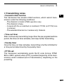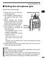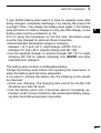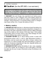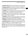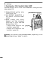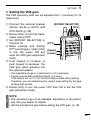
1
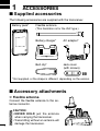
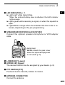
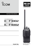
Limited functions only
INSTRUCTION MANUAL
VHF TRANSCEIVERS
iF3000
Series
UHF TRANSCEIVERS
iF4000
Series
This device complies with Part 15 of the FCC
Rules. Operation is subject to the condition that
this device does not cause harmful interference.
FOREWORD
READ ALL INSTRUCTIONS carefully and completely before
using the transceiver.
SAVE THIS INSTRUCTION MANUAL— This instruction
manual contains important operating instructions for the IC-F3001/
IC-F3003/IC-F3006/IC-F3008 VHF TRANSCEIVERS and the
IC-F4001/IC-F4003/IC-F4006/IC-F4008 UHF TRANSCEIVERS.
EXPLICIT DEFINITIONS
WORD
RDANGER
RWARNING
CAUTION
NOTE
DEFINITION
Personal death, serious injury or an explosion may occur.
Personal injury, fire hazard or electric shock
may occur.
Equipment damage may occur.
If disregarded, inconvenience only. No risk
of personal injury, fire or electric shock.
Icom, Icom Inc. and the Icom logo are registered trademarks of Icom Incorporated (Japan) in Japan, the United States, the United Kingdom, Germany, France,
Spain, Russia and/or other countries.
PRECAUTIONS
R DANGER! NEVER short the terminals of the battery pack.
R WARNING! NEVER hold the transceiver so that the antenna
is very close to, or touching exposed parts of the body, especially
the face or eyes, while transmitting. The transceiver will perform
best if the microphone is 5 to 10 cm (2 to 4 in.) away from the lips
and the transceiver is vertical.
R WARNING! NEVER operate the transceiver with a headset
or other audio accessories at high volume levels.
CAUTION: NEVER use non-Icom battery packs/chargers, to prevent the loss of the transceiver’s good performance and warranty.
CAUTION: MAKE SURE the flexible antenna and battery pack
are securely attached to the transceiver, and that the antenna and
battery pack are dry before attachment. Exposing the inside of the
transceiver to water will result in serious damage to the transceiver.
DO NOT push [PTT] when not actually intending to transmit.
DO NOT use or place the transceiver in direct sunlight or in areas
with temperatures below –30°C (+22°F) or above +60°C (+140°F).
DO NOT modify the transceiver. The transceiver warranty does
not cover any problems caused by unauthorized modification.
KEEP the transceiver away from heavy rain, and never immerse
it in the water. The transceiver meets IP54* requirements for dustprotection and splash resistance. However, once the transceiver
has been dropped, dust-protection and splash resistance cannot
be guaranteed because of possible damage to the transceiver’s
case or the waterproof seal.
* Only when the battery pack and jack cover are attached.
MAKE SURE to turn the transceiver power OFF before connecting the supplied/optional equipment.
ii
FCC INFORMATION
• FOR CLASS B UNINTENTIONAL RADIATORS:
This equipment has been tested and found to comply with the limits
for a Class B digital device, pursuant to part 15 of the FCC Rules.
These limits are designed to provide reasonable protection against
harmful interference in a residential installation. This equipment
generates, uses and can radiate radio frequency energy and, if not
installed and used in accordance with the instructions, may cause
harmful interference to radio communications. However, there is no
guarantee that interference will not occur in a particular installation.
If this equipment does cause harmful interference to radio or television reception, which can be determined by turning the equipment
off and on, the user is encouraged to try to correct the interference
by one or more of the following measures:
• Reorient or relocate the receiving antenna.
• Increase the separation between the equipment and receiver.
• Connect the equipment into an outlet on a circuit different from
that to which the receiver is connected.
• Consult the dealer or an experienced radio/TV technician for
help.
CAUTION: Changes or modifications to this device, not expressly
approved by Icom Inc., could void your authority to operate this
transceiver under FCC regulations.
iii
TABLE OF CONTENTS
FOREWORD......................................................................................... i
EXPLICIT DEFINITIONS....................................................................... i
PRECAUTIONS.................................................................................... ii
FCC INFORMATION............................................................................iii
TABLE OF CONTENTS....................................................................... iv
1 ACCESSORIES.......................................................................... 1–4
■ Supplied accessories................................................................... 1
■ Accessory attachments............................................................... 1
2 PANEL DESCRIPTION............................................................. 5–11
■ Front, top and side panels........................................................... 5
■ LED indicator............................................................................... 7
■ Programmable function keys....................................................... 8
3 BASIC OPERATION............................................................... 12–22
■ Turning power ON...................................................................... 12
■ Channel selection...................................................................... 13
■ Call procedure........................................................................... 14
■ Receiving and transmitting........................................................ 15
■ Setting the microphone gain...................................................... 18
■ Setting the squelch level............................................................ 19
■ Output power selection.............................................................. 20
■ Priority A channel selection....................................................... 20
■ MDC 1200 system operation..................................................... 20
■ Emergency Call......................................................................... 21
■ Lone Worker Emergency Call.................................................... 22
4 BATTERY CHARGING........................................................... 23–31
■ Caution (for the BP-264 ni-mh battery)..................................... 23
■ Caution (for the BP-265 li-ion battery)..................................... 25
■ Battery chargers........................................................................ 28
5 BATTERY CASE........................................................................... 32
■ Optional battery case (BP-263)................................................. 32
6 OPTIONS................................................................................ 33–38
■ VOX function.............................................................................. 36
7 SAFETY TRAINING INFORMATION...................................... 39–40
1
2
3
4
5
6
7
8
9
10
11
12
13
14
15
16
17
18
19
20
iv
1
ACCESSORIES
■ Supplied accessories
The following accessories are supplied with the transceiver.
Battery pack*
Flexible antenna
(This illustration is for the VHF type.)
Battery charger*
AC adapter*
Belt clip*
Jack cover
(with screws)
* Not supplied, or the shape is different, depending on the version.
■ Accessory attachments
D Flexible antenna
Connect the flexible antenna to the antenna connector.
CAUTION:
•N
EVER HOLD just the antenna
when carrying the transceiver.
• Transmitting without an antenna will
damage the transceiver.
ACCESSORIES
1
D Belt clip
To attach the belt clip:
➥ Slide the belt clip in the direction of the arrow until the belt clip
locks in place, and makes a ‘click’ sound.
Belt clip
1
2
3
4
5
Battery pack
6
7
8
9
10
11
To detach the belt clip:
q Remove the battery pack from the transceiver, if it is attached.
(p. 3)
w Lift the tab up (q), and slide the belt clip in the direction of the
arrow (w).
q
w
12
13
14
15
16
17
Tab
18
19
20
1
ACCESSORIES
D Battery pack/case
To attach the battery pack/case:
q
Fit the battery pack/case in the direction of the arrow (q), then
close.
wHook the latch until it makes a ‘click’ sound (w).
q
Battery pack/case
w
Latch
To remove the battery pack/case:
Unhook the latch (e), and lift up the battery pack/case in the
direction of the arrow (r).
r
e
Be careful! The latch is tightly locked, so use caution when releasing it. DO NOT use your finger nail. Use the edge of a coin or
screwdriver tip to carefully release it.
ACCESSORIES
1
NEVER remove or attach the battery pack/case when the transceiver is wet or soiled. This may result in water or dust getting into
the transceiver, battery pack/case, and may result in them being
damaged.
NOTE: Keep the battery terminals clean. It’s a good idea to clean
the battery terminals once a week.
1
2
3
4
5
6
D Jack cover
Attach the jack cover when the optional equipment is not used.
7
To attach the jack cover:
q Attach the jack cover to the
[SP MIC] jack.
w Tighten the screws.
8
To detach the jack cover:
e Remove the screws with a
phillips screwdriver.
r Detach the jack cover to connect the optional equipment.
9
10
11
12
13
w
14
e
15
q
w
e
r
16
17
18
19
20
2
PANEL DESCRIPTION
■ Front, top and side panels
q ROTARY
SELECTOR
i ANTENNA
CONNECTOR
u PTT SWITCH
y UPPER KEY
t LOWER KEY
w VOLUME
CONTROL
e LED INDICATOR
Speaker
r SPEAKERMICROPHONE
JACK
Microphone
qROTARY SELECTOR
Rotate to select the pre-programmed memory channels.
wVOLUME CONTROL [VOL]
Rotate to turn the power ON/OFF, and adjust the audio level.
PANEL DESCRIPTION
2
1
eLED INDICATOR (p. 7)
➥ Lights red* while transmitting.
*When the optional battery case is attached, the LED indicator
lights orange.
➥ Lights green while receiving a signal, or when the squelch is
open.
➥ Lights/blinks orange when the matched 2/5-tone code is received, depending on the pre-programming.
rSPEAKER-MICROPHONE JACK [SP MIC]
Connect the optional speaker-microphone or VOX adapter
cable.
2
3
4
5
6
7
8
9
10
11
Jack cover
NOTE: Attach the jack cover
when the optional equipment
is not used. (p. 4)
12
13
14
15
tLOWER KEY [Lower]
yUPPER KEY [Upper]
The desired function can be assigned by your dealer. (p. 8)
uPTT SWITCH [PTT]
Push and hold to transmit; release to receive.
iANTENNA CONNECTOR
Connect the antenna.
16
17
18
19
20
2
PANEL DESCRIPTION
■ LED indicator
The LED indicator indicates the status of various
parameters of the transceiver as follows;
(Ref.; R=Red, G=Green, O=Orange)
• TX: Lights Red while transmitting a signal.
R*
• RX: Lights Green while receiving a signal.
G
• Call LED (ON): Turns ON while receiving a matched 2/5-tone.
O
E D ON
• Call LED (Blink): Blinks while receiving a matched 2/5-tone.
E D Blink
O
O
• Fast/Slow scan: Blinks when the Fast/Slow scan is activated.
G
c an
G
• Low Battery 1: You should charge the battery. (blinks slowly)
G
B ATT1
G
• Low Battery 2: You must charge the battery. (blinks fast)
G
B ATT2
G
G
G
• TX low Battery 1: Low Battery was detected during TX mode.
R*
w BATT1
R*
• TX low Battery 2: Very Low Battery was detected during TX mode.
w BATT2
R*
R*
R*
R*
• Channel Error: A non-programmed channel is selected.
R O R O R O R O R O R O R O R O
* Lights (or blinks) orange when the optional battery case is attached.
PANEL DESCRIPTION
2
■ Programmable function keys
The following functions can be assigned to the [Upper] and [Lower]
programmable function keys.
Consult your Icom dealer or system operator for details concerning
your transceiver’s programming.
SCAN A
➥ Push to start and cancel the scanning operation.
➥ When the Power ON scan function is turned ON, push to pause
the scanning operation. The paused scan resumes after the
specified time period has passed.
1
2
3
4
5
6
7
8
SCAN B
Push to start and cancel the scanning operation.
If the scan pauses for any reason, except being cancelled by this
key, it will resume after a specified time period has passed.
9
PRIORITY A CHANNEL, PRIORITY B CHANNEL
Push to select the Priority A or Priority B channel.
12
PRIORITY A CHANNEL (REWRITE),
PRIORITY B CHANNEL (REWRITE)
➥ Push to select the Priority A or Priority B channel.
➥ Push and hold [Prio A (Rewrite)] or [Prio B (Rewrite)] for 1 sec.
to assign the operating channel to Priority A or Priority B channel, respectively.
MEMORY CHANNELS 1, 2, 3, 4
Push to directly select memory channel 1, 2, 3 or 4, if programmed.
Consult your dealer for details.
10
11
13
14
15
16
17
18
19
20
2
PANEL DESCRIPTION
MONITOR, MONITOR (AUDIBLE)
➥ Push to turn the CTCSS (DTCS) or 2/5-tone squelch Mute ON
or OFF.
• Only during LMR operation, push to open any squelch functions, or deactivate any mute functions.
• Only during PMR operation, push to activate one or two of the
following functions* on each channel.
- Push and hold to un-mute the channel (Audible mode).
- Push to mute the channel (Inaudible mode).
- Push to send a ‘reset code’ after the communication is finished.
*Ask your dealer for details.
OTE: The un-mute condition may automatically return to
N
the mute condition, after a specified time period.
➥D
epending on the presetting, pushing and holding this key for
1 sec. cancels a scan.
LOCK
Push and hold to electronically lock all programmable keys except
[Moni(Audi)], [Call] (including Call A and Call B), [Emergency],
[Surveillance] and [Lone Worker].
LONE WORKER (p. 22)
➥ Push to turn the Lone Worker function OFF.
➥ Push and hold to turn the Lone Worker function ON.
• When the Lone Worker function is turned ON, and no operation is
performed for the specified time period, the Emergency function is
automatically turned ON.
HIGH/LOW (p. 20)
Select the transmit output power level temporarily or permanently,
depending on the presetting.
• Ask your dealer for the output power level for each selection.
PANEL DESCRIPTION
2
TALK AROUND
➥ Push to turn the Talk Around function OFF.
➥ Push and hold to turn the Talk Around function ON.
• The Talk Around function equalizes the transmit frequency to the
receive frequency for transceiver-to-transceiver communication.
WIDE/NARROW
➥ Push to switch the IF bandwidth to Wide.
• The wide passband width can be selected from 20 or 25 kHz using
the optional cloning software (PMR operation only). Ask your dealer
for details.
➥ Push and hold to switch the IF bandwidth to Narrow.
DTMF AUTODIAL
Push to transmit a programmed DTMF code.
CALL, CALL A, CALL B
Push to transmit a 2/5-tone code.
• Tone call transmission may be necessary before you call another station, depending on your signalling system.
• [Call A] and/or [Call B] keys may be available when your system employs selective ‘Individual/Group’ calls. Ask your dealer which call is
assigned to each key.
1
2
3
4
5
6
7
8
9
10
11
12
13
14
15
16
17
18
19
20
10
2
PANEL DESCRIPTION
EMERGENCY
Push and hold for specified time period to transmit an emergency
call.
• The emergency call transmits with beeps, and the LED indicator lights
red.
• The transceiver can transmit an emergency call without the beep
sounding and the LED indicator lighting. Ask your dealer for details.
• If you want to cancel the emergency call, push and hold the key again
before transmitting the call.
• The emergency call is transmitted one time only, or repeatedly until receiving an acknowledgement signal, or until the power is turned OFF.
When a matched 5-tone code signal is received, the emergency function can be cancelled depending on the presetting. (PMR operation
only)
SURVEILLANCE
➥ Push to turn the Surveillance function OFF.
➥ Push and hold to turn the Surveillance function ON.
• When this function is turned ON, the beep is not heard and the LED
does not light when a signal is received, or a key is pushed.
SIREN
Push and hold for 1 sec. to emit a siren sound.
This function can be used for situations other than an emergency
alert, such as a security alarm for example.
The transceiver emits the siren sound until the power is turned
OFF.
11
BASIC OPERATION
■ Turning power ON
3
1
Prior to using the transceiver for the first time, the battery pack
must be fully charged for optimum life and operation. (p. 23)
[VOL]
➥Rotate [VOL] to turn power ON.
2
3
4
5
6
D Battery type selection
The battery type must be selected according to the battery pack or
case when it is changed, but only the first time it is used.
Check the battery type before you begin the selection procedure.
One to three beep(s) sound in sequence, so you must repeat the
steps until the number of beeps matches your battery type.
For example, if your battery type is a Li-Ion battery pack, you must
repeat the procedure until 1 beep is heard.
qSet [ROTARY SELECTOR] to any
channel other than Channel 16.
w
Rotate [VOL] to turn the transceiv-
[ROTARY SELECTOR]
[VOL]
er power OFF.
e
While pushing and holding [PTT],
rotate [VOL] to turn the power ON.
• You should hold [PTT] until the beep
sounds. (It takes approx. 5 sec.)
[PTT]
• 1 beep sounds when the Li-Ion battery is selected.
• 2 beeps sound when the battery
case is selected.
• 3 beeps sound when the Ni-MH battery is selected.
rAfter the beep sounds, release [PTT].
tRepeat steps w to r until you select the attached battery type.
NOTE: This operation may not be available, depending on the
presetting. Ask your dealer for details.
7
8
9
10
11
12
13
14
15
16
17
18
19
20
12
3
BASIC OPERATION
■ Channel selection
Several types of channel selecting methods are available. They
may differ, according to your system set up.
To select a desired operating channel, do one of the following.
• Rotate [ROTARY SELECTOR].
• Push one of memory channel keys, [MR-CH 1] to [MR-CH 4].
AUTOMATIC SCAN TYPE:
Selecting a channel is not necessary for this type. When turning the
power ON, the transceiver automatically starts scanning. Scanning
stops when a call is received.
NOTE: If the Move to Priority A channel at Power ON function
(p. 20) is turned ON, the transceiver does not start scanning at
power ON.
13
BASIC OPERATION
3
■ Call procedure
1
When your system employs tone signalling (excluding CTCSS and
DTCS), the tone call procedure may be necessary prior to voice
transmission. The tone signalling that is employed in the transceiver
may be a selective calling system, which allows you to call only
specific station(s), and prevent unwanted stations from contacting
you.
q Select a desired TX code channel or 2/5-tone code, according to
your System Operator’s instructions.
• This may not be necessary, depending on programming.
w Push [Call] (assigned to one of the dealer programmable keys.)
(p. 10)
e After transmitting a 2/5-tone code, the remainder of your communication can be carried out normally.
Selective calling
Non-selective calling
2
3
4
5
6
7
8
9
10
11
12
13
14
15
16
17
18
19
20
14
3
BASIC OPERATION
■ Receiving and transmitting
CAUTION: Transmitting without an antenna will damage the
transceiver. See p. 1 for antenna attachment.
Receiving:
q Rotate [VOL] to turn power ON.
w Rotate [ROTARY SELECTOR], or push one of the memory channel keys, [MR-CH 1] to [MR-CH 4], to select a channel.
e When receiving a call, adjust the audio output to a comfortable
listening level.
NOTE: When a matched RX code signal is received, audio from
the microphone is automatically transmitted for a specified time
period.*
* Depending on the presetting. Ask your dealer for details.
Transmitting:
Wait for the channel to become clear to avoid interference.
q While pushing and holding [PTT], speak into the microphone at
a normal voice level.
w Release [PTT] to return to receive.
IMPORTANT: To maximize the readability of your signal;
1. Pause briefly after pushing [PTT].
2. Hold the microphone 5 to 10 cm (2 to 4 inches) from your mouth,
then speak into the microphone at a normal voice level.
15
BASIC OPERATION
3
1
D Transmitting notes
• Transmit inhibit function
The transceiver has several inhibit functions, which restrict transmission under the following conditions:
- The channel is muted. (PMR operation only)
- The channel is busy.
- A signal with the un-matched (or matched) CTCSS (or DTCS) tone
is received.
- The selected channel is a ‘receive only’ channel.
• Time-out timer
After continuously transmitting longer than the pre-programmed time
period, the time-out timer activates, and stops further transmitting.
• Penalty timer
Once the time-out timer activates, transmitting is further inhibited for
a time period determined by the penalty timer.
•PTTID call
The transceiver automatically sends the ID code (5-tone, DTMF,
BIIS or MDC system) when [PTT] is pushed (beginning of the transmission) and/or released (end of transmission), depending on the
presetting.
2
3
4
5
6
7
8
9
10
11
12
13
14
15
16
17
18
19
20
16
3
BASIC OPERATION
D DTMF transmission
If the transceiver has [DTMF Autodial] assigned to it, the automatic
DTMF transmission function is usable.
➥Push [DTMF Autodial] to transmit the DTMF code.
D Receiving a Stun, Kill and Revive command
The dispatcher can send a 2/5-tone signal that will stun, kill or revive your transceiver.
When the Stun command is received, a beep sounds*, and the
transceiver becomes unusable. Receiving a Revive command is
necessary to operate the transceiver again in this case.
When the Kill command is received, a beep sounds*, and the transceiver becomes unusable (the transceiver switches to the cloning
required condition). Cloning the transceiver is necessary to operate
the transceiver again in this case.
* Depending on the presetting. Ask your dealer for details.
17
BASIC OPERATION
3
■ Setting the microphone gain
1
Adjusts the microphone gain.
2
Rotate [VOL] to turn the transq
ceiver power OFF.
wSet [ROTARY SELECTOR] to
any channel other than Channel 16.
e While pushing and holding
[Lower], rotate [VOL] to turn the
power ON and enter the microphone gain adjustment mode.
rPush [Upper] to increase, or
push [Lower] to decrease the
microphone gain.
[ROTARY SELECTOR]
[VOL]
3
4
5
6
7
8
[Upper]
[Lower]
• The adjustable range is 1 (minimum) to 4 (maximum).
• A beep sounds after pushing
[Upper] or [Lower].
If the level is set on 1 or 4, an
error beep sounds after pushing.
Therefore, you can determine the current level setting by the type
of beep that sounds.
tRotate [VOL] to turn the power OFF, then ON to exit the microphone gain adjustment mode.
NOTE:
• This operation may not be available, depending on the presetting. Ask your dealer for details.
• When using the VOX function, we recommend setting the microphone gain to 3. However, you can adjust it to suit your operating environment (including your headset performance).
9
10
11
12
13
14
15
16
17
18
19
20
18
3
BASIC OPERATION
■ Setting the squelch level
The squelch circuit mutes the received audio signal, depending on
the signal strength.
Rotate [VOL] to turn the transq
[ROTARY SELECTOR]
ceiver power OFF.
[VOL]
wSet [ROTARY SELECTOR] to
any channel other than Channel 16.
eWhile pushing and holding
[PTT] and [Lower], rotate [VOL]
[PTT]
to turn the power ON and enter
the squelch level adjustment
[Upper]
mode.
rPush [Upper] to increase the [Lower]
squelch level (tight squelch), or
push [Lower] to decrease the
squelch level (loose squelch).
• The adjustable range is 0 (loose
squelch) to 9 (tight squelch).
• A beep sounds after pushing [Upper] or [Lower].
If the level is set on 0 or 9, an error beep sounds after pushing.
Therefore, you can determine the current level setting by the type
of beep that sounds.
tRotate [VOL] to turn the power OFF, then ON to exit the squelch
level adjustment mode.
NOTE: This operation may not be available, depending on the
presetting. Ask your dealer for details.
19
BASIC OPERATION
3
■ Output power level selection
If the transceiver has [High/Low] assigned to it, the transmit output
power level can be selected, depending on the presetting.
When the battery case is selected as the battery type, or the battery voltage drops to a low power level and the LED indicator status is “Low Battery 2,” the output power automatically switches to
“Low 1.” (pgs. 7, 12)
➥Push [High/Low] to select the transmit output power level.
• 1 beep sounds when “Low 1” is selected.
• 2 beeps sound when “Low 2” is selected.
• 3 beeps sound when “High” is selected.
■ Priority A channel selection
1
2
3
4
5
6
7
8
9
10
Depending on the presetting, the Priority A channel is selected
each time the transceiver power is turned ON.
11
■ MDC 1200 system operation
13
The MDC 1200 signaling system enhances your transceiver’s capabilities. It allows PTT ID* and Emergency signaling.
*When [PTT] is pushed and/or released, the transceiver transmits your
station ID.
D Transmitting an Emergency Call
The MDC 1200 system’s Emergency feature can be accessed
using the [Emergency] key. The transceiver will send an Emergency
MDC 1200 system command once, or repeatedly for a programmed
number of times until it receives the acknowledgement signal.
The emergency call can be transmitted without a beep sound depending on how the emergency function is programmed. Ask your
dealer for details.
12
14
15
16
17
18
19
20
20
3
BASIC OPERATION
■ Emergency Call
When [Emergency] is pushed for the specified time period*, the
emergency signal is transmitted once, or repeatedly, on the specified emergency channel.
A repeat emergency signal is automatically transmitted until the
transceiver receives an acknowledgement signal, or you turn the
transceiver power OFF.
When no emergency channel is specified, the signal is transmitted
on the previously selected channel.
If you want to cancel the emergency call, push and hold [Emergency] again before transmitting the call.
If your transceiver is programmed for Silent operation, you can
transmit an Emergency call without the beep sounding and the LED
indicator lighting.
IMPORTANT: It is recommended to set an emergency channel
individually to provide the certain emergency call operation.
D NOTES
Depending on the presetting, the following functions are automatically activated. Ask your dealer for details.
• Auto TX function
After the emergency call transmission, audio from the microphone
is automatically transmitted for a specified time period.*
• Auto RX function
After the emergency call transmission, the transceiver stands by in
the audible mode for the specified time period.*
* Depending on the presetting. Ask your dealer for details.
21
BASIC OPERATION
3
■ Lone Worker Emergency Call
When the Lone Worker function is turned ON, and no operation is
performed for the specified time period*, the transceiver enters the
emergency mode, and then the countdown for the emergency call
transmission starts.
After the specified time period* has passed, an emergency call is
automatically transmitted once, or repeatedly*.
If someone operates the transceiver before the call is transmitted, the
transceiver exits the emergency mode, and the emergency call is cancelled.
1
2
3
4
5
6
7
* Depending on the presetting. Ask your dealer for details.
8
qPush and hold to turn the Lone Worker function ON.
wPush to turn the Lone Worker function OFF.
9
10
11
12
13
14
15
16
17
18
19
20
22
4
BATTERY CHARGING
■ Caution (for the BP-264 ni-mh battery)
R DANGER! NEVER short terminals (or charging terminals) of the
battery pack. Also, current may flow into nearby metal objects such
as a necklace, so be careful when placing battery packs (or the
transceiver) in handbags, etc.
Simply carrying with or placing near metal objects such as a necklace, etc. may cause shorting. This may damage not only the battery pack, but also the transceiver.
R DANGER! NEVER incinerate used battery packs. Internal battery gas may cause an explosion.
R DANGER! NEVER immerse the battery pack in water. If the battery pack becomes wet, be sure to wipe it dry BEFORE attaching
it to the transceiver.
CAUTION: Always use the battery within the specified temperature
range, –5˚C to +60˚C (+23˚F to +140˚F). Using the battery out of its
specified temperature range will reduce the battery’s performance
and battery life.
CAUTION: Shorter battery life could occur if the battery is left completely discharged, or in an excessive temperature environment
(above +55˚C; +131˚F) for an extended period of time. If the battery
must be left unused for a long time, it must be detached from the
radio after charging. Keep it safely in a cool dry place at the following temperature range:
–20˚C to +45˚C (–4˚F to +113˚F) (up to a month)
–20˚C to +35˚C (–4˚F to +95˚F)
(up to six months)
–20˚C to +25˚C (–4˚F to +77˚F)
(up to a year*)
* We recommend charging the battery pack every 6 months.
Clean the battery terminals to avoid rust or misscontact.
Keep the battery terminals clean. It’s a good idea to clean the battery terminals once a week.
23
BATTERY CHARGING
4
1
If your Ni-MH battery pack seems to have no capacity, even after
being charged, completely discharge it by leaving the power ON
overnight. Then, fully charge the battery pack again. If the battery
pack still does not retain a charge (or only very little charge), a new
battery pack must be purchased. (p. 33)
Prior to using the transceiver for the first time, the battery pack
must be fully charged for optimum life and operation.
• Recommended temperature range for charging:
between +10°C and +40°C (rapid charge: with BC-191) or
between 0°C and +45°C (regular charge: with BC-192)
• Use the supplied charger or optional charger (BC-191 for rapid
charging, BC-192 for regular charging) only. NEVER use other
manufacturers’ chargers.
The battery pack contains a rechargable battery.
Charge the battery pack before first operating the transceiver, or
when the battery pack becomes exhausted.
If you want to prolong the battery life, the following points should
be observed:
• Avoid over charging. The charging time period by the BC-192
should be less than 48 hours.
• Use the battery pack until it becomes almost completely exhausted, under normal conditions. We recommend battery charging after transmitting becomes impossible.
2
3
4
5
6
7
8
9
10
11
12
13
14
15
16
17
18
19
20
24
4
BATTERY CHARGING
■ Caution (for the BP-265 li-ion battery)
Misuse of Li-Ion batteries may result in the following hazards:
smoke, fire, or the battery may rupture. Misuse can also cause
damage to the battery or degradation of battery performance.
R DANGER! Use and charge only specified Icom battery packs
with Icom radios or Icom chargers. Only Icom battery packs are
tested and approved for use with Icom radios or charged with Icom
chargers. Using third-party or counterfeit battery packs or chargers
may cause smoke, fire, or cause the battery to burst.
D Battery caution
R DANGER! DO NOT hammer or otherwise impact the battery. Do
not use the battery if it has been severely impacted or dropped, or if
the battery has been subjected to heavy pressure. Battery damage
may not be visible on the outside of the case. Even if the surface
of the battery does not show cracks or any other damage, the cells
inside the battery may rupture or catch fire.
R DANGER! NEVER use or leave battery packs in areas with
temperatures above +60˚C (+140˚F). High temperature buildup in
the battery, such as could occur near fires or stoves, inside a sun
heated car, or in direct sunlight may cause the battery to rupture or
catch fire. Excessive temperatures may also degrade battery performance or shorten battery life.
R DANGER! DO NOT expose the battery to rain, snow, seawater,
or any other liquids. Do not charge or use a wet battery. If the battery gets wet, be sure to wipe it dry before using. The battery is not
waterproof.
25
BATTERY CHARGING
4
1
R DANGER! NEVER incinerate used battery packs, since internal
battery gas may cause them to rupture, or may cause an explosion.
R DANGER! NEVER solder the battery terminals or NEVER modify the battery pack. This may cause heat generation, and the battery may rupture, emit smoke or catch fire.
R DANGER! Use the battery only with the transceiver for which it
is specified. Never use a battery with any other equipment, or for
any purpose that is not specified in this instruction manual.
R DANGER! If fluid from inside the battery gets in your eyes, blindness can result. Rinse your eyes with clean water, without rubbing
them, and see a doctor immediately.
R WARNING! Immediately stop using the battery if it emits an abnormal odor, heats up, or is discolored or deformed. If any of these
conditions occur, contact your Icom dealer or distributor.
R WARNING! Immediately wash, using clean water, any part of
the body that comes into contact with fluid from inside the battery.
2
3
4
5
6
7
8
9
10
11
12
R WARNING! NEVER put the battery in a microwave oven, highpressure container, or in an induction heating cooker. This could
cause a fire, overheating, or cause the battery to rupture.
13
CAUTION: Always use the battery within the specified temperature
range, –20˚C to +60˚C (–4˚F to +140˚F). Using the battery out of its
specified temperature range will reduce the battery’s performance
and battery life.
15
14
16
17
18
19
20
26
4
BATTERY CHARGING
CAUTION: Shorter battery life could occur if the battery is left fully
charged, completely discharged, or in an excessive temperature
environment (above +50˚C; +122˚F) for an extended period of time.
If the battery must be left unused for a long time, it must be detached from the radio after discharging.
You may use the battery until the remaining capacity is about half,
then keep it safely in a cool dry place within the temperature range
as shown below:
–20˚C to +50˚C (–4˚F to +122˚F) (up to a month)
–20˚C to +35˚C (–4˚F to +95˚F)
(up to three months)
–20˚C to +20˚C (–4˚F to +68˚F)
(up to a year)
D Charging caution
R DANGER! NEVER charge the battery pack in areas with extremely high temperatures, such as near fires or stoves, inside
a sun heated car, or in direct sunlight. In such environments, the
safety/protection circuit in the battery will activate, causing the battery to stop charging.
R WARNING! DO NOT charge or leave the battery in the battery
charger beyond the specified time for charging. If the battery is not
completely charged by the specified time, stop charging and remove the battery from the battery charger. Continuing to charge the
battery beyond the specified time limit may cause a fire, overheating, or the battery may rupture.
R WARNING! NEVER insert the transceiver (battery attached to
the transceiver) into the charger if it is wet or soiled. This could
corrode the battery charger terminals or damage the charger. The
charger is not waterproof.
27
CAUTION: DO NOT charge the battery outside of the specified
temperature range: BC-193 (+10˚C to +40˚C; +50˚F to +104˚F).
Icom recommends charging the battery at +20˚C (+68˚F). The battery may heat up or rupture if charged out of the specified temperature range. Additionally, battery performance or battery life may be
reduced.
BATTERY CHARGING
4
■ Battery chargers
1
D Using the BC-191 to rapid charge the BP-264
2
The BC-191 provides rapid charging of the Ni-MH battery pack
(BP-264 only). Never use for any other battery pack.
Charging time period: Approx. 2 hours (for the BP-264)
3
The following item is additionally required:
• An AC adapter (not supplied with some versions) or the DC power
cable (OPC-515L/CP-23L).
5
Battery pack
Transceiver
Turn power OFF
4
6
7
8
9
10
11
AC adapter
(A different type,
or no AC adapter is supplied,
depending on
the version.)
Optional OPC-515L*
(for power source) or
CP-23L (for 12 V cigarette lighter socket)
can be used instead
of the AC adapter.
* About OPC-515L
White line:
Black line :
CAUTION: NEVER connect the
OPC-515L to a power source
using reverse polarity.
This will ruin the battery charger.
12
13
14
Screws*
(S elf tapping screw:
M3.5 × at least 30 mm)
*Purchase separately.
Using screws is recommended to secure the
charger.
Charge indicator
• Lights orange:
While charging.
• Lights green:
Charging is completed.
15
16
17
18
19
20
28
4
BATTERY CHARGING
D Using the BC-192 to regular charge the BP-264
The BC-192 provides regular charging of the Ni-MH battery pack
(BP-264 only). Never use for any other battery pack.
Charging time period (with BC-147S): Approx. 16 hours (for the BP-264)
The following item is additionally required:
• An AC adapter (not supplied with some versions) or the DC power
cable (OPC-515L).
Battery pack
Transceiver
Turn power OFF
AC adapter
(A different type,
or no AC adapter is supplied,
depending on
the version.)
Optional OPC-515L*
(for power source)
can be used instead
of the AC adapter.
* About OPC-515L
White line:
Black line :
CAUTION: NEVER connect the
OPC-515L to a power source
using reverse polarity.
This will ruin the battery charger.
Charging time period differs
depending on the input voltage.
12 V : Approx. 36 hours
13.8 V : Approx. 21 hours
16 V : Approx. 16 hours
29
Screws*
(S elf tapping screw:
M3.5 × at least 30 mm)
*Purchase separately.
Using screws is recommended to secure the
charger.
Charge indicator
Lights green while charging.
NOTE:
The charge indicator will not go
out even after a battery pack is
fully charged.
BATTERY CHARGING
4
D Using the BC-193 to rapid charge the BP-265
The BC-193 provides rapid charging of the Li-Ion battery pack
(BP-265 only). Never use for any other battery pack.
Charging time period: Approx. 2.5 hours (for the BP-265)
The following item is additionally required:
• An AC adapter (not supplied with some versions) or the DC power
cable (OPC-515L/CP-23L).
Battery pack
1
2
3
4
5
Transceiver
6
Turn power OFF
7
8
9
10
AC adapter
(A different type,
or no AC adapter is supplied,
depending on
the version.)
Optional OPC-515L*
(for power source) or
CP-23L (for 12 V cigarette lighter socket)
can be used instead
of the AC adapter.
* About OPC-515L
White line:
Black line :
CAUTION: NEVER connect the
OPC-515L to a power source
using reverse polarity.
This will ruin the battery charger.
11
12
13
Screws*
(S elf tapping screw:
M3.5 × at least 30 mm)
*Purchase separately.
Using screws is recommended to secure the
charger.
Charge indicator
• Lights orange:
While charging.
• Lights green:
Charging is completed.
14
15
16
17
18
19
20
30
4
BATTERY CHARGING
IMPORTANT:
Ensure the tabs on the battery pack are correctly aligned with
the guide rails inside the charger.
Tabs
Guide rail
31
BATTERY CASE
■ Optional battery case (BP-263)
5
When using the optional battery case, install 6 × AA (LR6) size
alkaline batteries, as illustrated below.
q Remove the battery case if it is attached. (pgs. 3, 4)
w Install 6 × AA (LR6) size alkaline batteries, as shown below.
• Install only alkaline batteries.
• Be sure to observe the correct polarity.
1
2
3
4
5
6
7
Be careful! The negative
terminals of the battery case
protrude from the body, so
pay attention not to injure
your fingers when inserting
the batteries.
e Attach the battery case. (pgs. 3, 4)
CAUTION:
• When installing batteries, make sure they are all the same
brand, type and capacity. Also, do not mix new and old batteries together.
• Keep the battery terminals clean. It’s a good idea to clean the
battery terminals once a week.
• Never incinerate used battery cells since internal battery gas
may cause them to rupture.
• Never expose a detached battery case to water. If the battery
case gets wet, be sure to wipe it dry before using it.
• Never use batteries whose insulated cover is damaged.
NOTE: When the optional battery case is attached, the battery
type must be selected as “Battery case operation” when turning
the transceiver ON. Ask your dealer for details. (p. 12)
8
9
10
11
12
13
14
15
16
17
18
19
20
32
6
OPTIONS
D BATTERY PACK
Battery pack Voltage
BP-263
BP-264
BP-265
Capacity
Battery life*1
Battery case for
AA (LR6) × 6 alkaline
7.2 V
7.4 V
1400 mAh (typ.)
1900 mAh (min.)
2000 mAh (typ.)
—*2
VHF
14.1 hrs.
UHF
13.7 hrs.
VHF
20.2 hrs.
UHF
19.6 hrs.
*1When the power save function is turned ON, and the operating time
is calculated under the following conditions;
TX : RX : standby = 5 : 5 : 90
*2 The average operating time depends on the alkaline cells used.
D CHARGERS
•BC-191 desktop charger + BC-123S ac adapter
For rapid charging of the Ni-MH battery pack. An AC adapter is
supplied with the charger, depending on the version.
Charging time period: approx. 2 hours for the BP-264.
•BC-192 desktop charger + BC-147S ac adapter
For regular charging of the Ni-MH battery pack. An AC adapter is
supplied with the charger, depending on the version.
Charging time period: approx. 16 hours for the BP-264.
•BC-193 desktop charger + BC-123S ac adapter
For rapid charging of the Li-Ion battery pack. An AC adapter is
supplied with the charger, depending on the version.
Charging time period: approx. 2.5 hours for the BP-265.
33
OPTIONS
6
D DC POWER CABLES
• CP-23L cigarette lighter cable
Allows charging of the battery pack through a 12 V cigarette lighter
socket. (For BC-191/BC-193)
• OPC-515L dc power cable
Allows charging of the battery pack using a power source instead
of the AC adapter.
D BELT CLIPS
•MB-124 belt clip
Exclusive alligator-type belt clip.
D ANTENNAS
•FA-SC73US/FA-SC56VS/FA-SC57VS stubby antennas
FA-SC73US: 450–490 MHz
FA-SC56VS: 150–162 MHz
FA-SC57VS: 160–174 MHz
•FA-SC25U/FA-SC57U/FA-SC72U/
FA-SC25V/FA-SC55V antennas
FA-SC25U : 400–430 MHz
FA-SC57U : 430–470 MHz
FA-SC72U : 470–520 MHz
FA-SC25V : 136–155 MHz
FA-SC55V : 146–174 MHz
•FA-SC61VC/FA-SC61UC cut antennas
FA-SC61VC: 136–174 MHz
FA-SC61UC: 380–520 MHz
1
2
3
4
5
6
7
8
9
10
11
12
13
14
15
16
17
18
19
20
34
6
OPTIONS
D OTHER OPTIONS
•AD-98FSC antenna connector converter
Allows you to connect an external antenna with a BNC connector.
•HM-158L/HM-159L speaker-microphone
Combination speaker-microphone that provides convenient operation while hanging the transceiver on your belt.
•HS-94/HS-95/HS-97 headset + OPC-2004 plug adapter cable
HS-94
: Ear hook type
HS-95
: Neck-arm type
HS-97
: Throat microphone
OPC-2004: Allows you to connect the HS-94/HS-95/HS-97 to the
transceiver. After connection, the VOX function can
be used.
Approved Icom optional equipment is designed for optimal performance
when used with an Icom transceiver.
Icom is not responsible for the destruction or damage to an Icom transceiver in the event the Icom transceiver is used with equipment that is
not manufactured or approved by Icom.
Some options may not be available in some countries. Please ask your
dealer for details.
35
OPTIONS
6
■ VOX function
1
The transceiver has a VOX function, which allows you hands-free
operation.
An optional headset (HS-94/HS-95/HS-97) and a plug adapter
cable (OPC-2004) are additionally required for operation.
• The VOX (voice operated transmission) function starts transmitting
when you speak into the microphone, without needing to push the PTT
switch; then, automatically returns to receive when you stop speaking.
D Optional unit connection
qRotate [VOL] to turn the transceiver power OFF.
wRemove the jack cover. (p. 4)
eConnect the optional headset (HS-94, HS-95 or HS-97) and
OPC-2004 as described below.
2
3
4
5
6
7
8
9
10
11
OPC-2004
HS-94
12
13
[VOL]
14
15
w
16
e
q
17
18
19
20
36
6
OPTIONS
D Turning the VOX function ON or OFF
The VOX function can be turned ON or OFF when turning the transceiver power ON.
Rotate [VOL] to turn the transq
ceiver power OFF.
wSet [ROTARY SELECTOR] to
any channel other than Channel 16.
e
While pushing and holding
[Upper], turn the transceiver
power ON to switch the VOX
function ON or OFF.
• 1 beep sounds when the VOX
function is turned OFF.
• 2 beeps sound when the VOX
function is turned ON.
[ROTARY SELECTOR]
[VOL]
[Upper]
NOTE: This operation may not be available, depending on the
presetting. Ask your dealer for details.
37
OPTIONS
6
D Setting the VOX gain
The VOX sensitivity level can be adjusted from 1 (minimum) to 10
(maximum).
Connect the optional headset
q
(HS-94, HS-95 or HS-97) and
[ROTARY SELECTOR]
[VOL]
OPC-2004. (p. 36)
w
Rotate [VOL] to turn the transceiver power OFF.
eSet [ROTARY SELECTOR] to
Channel 16.
[PTT]
rWhile pushing and holding
[PTT] and [Upper], rotate [VOL]
[Upper]
to turn the power ON and
[Lower]
enter the VOX gain adjustment
mode.
tPush [Upper] to increase, or
push [Lower] to decrease the
VOX gain while speaking into
the optional headset.
• The adjustable range is 1 (minimum) to 10 (maximum).
• A beep sounds after pushing [Upper] or [Lower].
If the level is set on 1 or 10, an error beep sounds after pushing.
Therefore, you can determine the current level setting by the type
of beep that sounds.
yRotate [VOL] to turn the power OFF, then ON to exit the VOX
gain adjustment mode.
NOTE:
• This operation may not be available, depending on the presetting. Ask your dealer for details.
• Set the microphone gain before setting the VOX gain. (p. 18)
1
2
3
4
5
6
7
8
9
10
11
12
13
14
15
16
17
18
19
20
38
7
SAFETY TRAINING INFORMATION
Your Icom radio generates RF electromagnetic energy
during transmit mode. This radio is designed for and
classified as “Occupational Use Only”, meaning it must
be used only during the course of employment by individuals aware of the hazards, and the ways to minimize
W ARN ING
such hazards. This radio is NOT intended for use by the
“General Population” in an uncontrolled environment.
This radio has been tested and complies with the FCC
RF exposure limits for “Occupational Use Only”. In addition, your Icom
radio complies with the following Standards and Guidelines with regard
to RF energy and electromagnetic energy levels and evaluation of such
levels for exposure to humans:
• F CC OET Bulletin 65 Edition 97-01 Supplement C, Evaluating
Compliance with FCC Guidelines for Human Exposure to Radio
Frequency Electromagnetic Fields.
• American National Standards Institute (C95.1-1992), IEEE Standard
for Safety Levels with Respect to Human Exposure to Radio Frequency Electromagnetic Fields, 3 kHz to 300 GHz.
• American National Standards Institute (C95.3-1992), IEEE Recommended Practice for the Measurement of Potentially Hazardous
Electromagnetic Fields– RF and Microwave.
• The accessories (antennas, batteries, belt clips, speaker-microphone, etc. that is listed on pages 33–35) are authorized for use
with this product. Use of accessories other than those specified may
result in RF exposure levels exceeding the FCC requirements for
wireless RF exposure.
C AU TIO N
39
To ensure that your expose to RF electromagnetic
energy is within the FCC allowable limits for occupational use, always adhere to the following guidelines:
SAFETY TRAINING INFORMATION
7
•D
O NOT operate the radio without a proper antenna attached, as
this may damaged the radio and may also cause you to exceed FCC
RF exposure limits. A proper antenna is the antenna supplied with
this radio by the manufacturer or antenna specifically authorized by
the manufacturer for use with this radio.
• DO NOT transmit for more than 50% of total radio use time (“50%
duty cycle”). “50% duty cycle” is also applicable to VOX/PTT mode.
Transmitting more than 50% of the time can cause FCC RF exposure compliance requirements to be exceeded. The radio is transmitting when the “LED indicator” lights red. You can cause the radio
to transmit by pressing the “PTT” switch or VOX function.
• ALWAYS keep the antenna at least 2.5 cm (1 inch) away from the
body when transmitting and only use the Icom belt-clip which is
listed on page 34 when attaching the radio to your belt, etc., to ensure FCC RF exposure compliance requirements are not exceeded.
To provide the recipients of your transmission the best sound quality, hold the antenna at least 5 cm (2 inches) from your mouth, and
slightly off to one side.
The information listed above provides the user with the information
needed to make him or her aware of RF exposure, and what to do to assure that this radio operates with the FCC RF exposure limits of this radio.
1
Electromagnetic Interference/Compatibility
During transmissions, your Icom radio generates RF energy that can
possibly cause interference with other devices or systems. To avoid such
interference, turn off the radio in areas where signs are posted to do so.
DO NOT operate the transmitter in areas that are sensitive to electromagnetic radiation such as hospitals, aircraft, and blasting sites.
14
Occupational/Controlled Use
The radio transmitter is used in situations in which persons are exposed as
consequence of their employment provided those persons are fully aware
of the potential for exposure and can exercise control over their exposure.
2
3
4
5
6
7
8
9
10
11
12
13
15
16
17
18
19
20
40
MEMO
MEMO
1
2
3
4
5
6
7
8
9
10
11
12
13
14
15
16
17
18
19
20
A-6797H-1EX
Printed in Japan
© 2009 Icom Inc.
Printed on recycled paper with soy ink.
1-1-32 Kamiminami, Hirano-ku, Osaka 547-0003, Japan