1
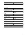
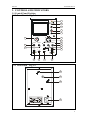
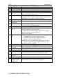
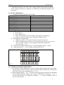
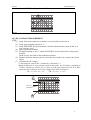
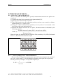
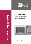
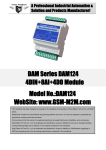
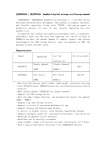
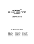
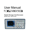
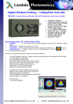
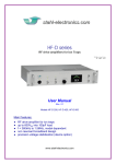
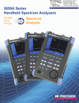
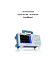
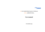
CQ5010B SINGLE TRACE
10MHZ OSCILLOSCOPE
USER’S MANUAL
⎯⎯⎯⎯⎯⎯⎯⎯⎯⎯⎯⎯⎯⎯⎯⎯⎯⎯⎯⎯⎯⎯⎯⎯⎯⎯⎯⎯⎯⎯⎯⎯⎯⎯
CONTENTS
⎯⎯⎯⎯⎯⎯⎯⎯⎯⎯⎯⎯⎯⎯⎯⎯⎯⎯⎯⎯⎯⎯⎯⎯⎯⎯⎯⎯⎯⎯⎯⎯⎯⎯
1. SAFETY PRECAUTION
2. SPECIFICATIONS
2.1 VERTICAL SYSTEM
2.2 TRIGGER SYSTEM
OS-10V
02/04/2001 Rev.2
2.3 HORIZONTAL SYSTEM
2.4 X-Y MODE
2.5 CALIBRATION
2.6 CRT
2.7 POWER SOURCE
2.8 PHYSICAL FEATURES
2.9 WORKING ENVIRONMENT
2.10 PRESSURE-PROOF TEST
3. CONTROL AND INDICATORS
3.1 CONTROL PANEL POSITION
3.2 FUNCTIONS OF CONTROL SWITCHES
3.3 OPERATING INSTRUCTION
4. MEASUREMENT
4.1 EXAMINATION AND ADJUSTMENT BEFORE TAKING MEASUREMENT
4.2 MEASUREMENT OF VOLTAGE
4.3 TIME MEASUREMENTS
4.4 PHASE DIFFERENCE MEASUREMENTS
4.5 X – Y MODE APPLICATIONS
5 . ACCESSORIES
1. SAFETY PRECAUTION
CQ5010B is a portable Oscilloscope with frequency bandwidth of 0~10 MHz and
sensitivity of 5mV/DIV~5V/DIV. Equipped with 10:1 probe which makes the sensitivity up to
50V/div. Sweep rate at 0.1S/DIV ~ 0.1µS/DIV on horizontal system. The oscilloscope is easy
to operate, and highly reliable. It is an ideal instrument for research, production, education,
and development in electronic device or circuitry.
The instrument is designed and tested in accordance with EN publication 61010, CAT II,
Pollution degree II and Overvoltage 600V. The instrument has been tested in accordance to
the following EC Directives (EMC):
a. EN50082
b. EN55011
c. EN61000-3-2
d. EN61000-3-3
The instrument complies with the requirements of the European Council Directive
89/336/EEC (EMC Directive) and 73/23/EEC (Low Voltage Directive). To ensure that the
instrument is used safety, follow all safety and operating instructions in this manual. If the
instrument is not used as described in this manual, the safety features might be impaired.
WARNING
1
OS-10V
02/04/2001 Rev.2
Non compliance with the warnings and/or the instructions for use may damage the
instrument and/or its components or injure the operator.
Take extreme care for the following conditions when using the instrument :
z
For your own safety and that of the instrument, you must follow the procedures described
in this instruction manual and especially read all the notes preceded by the symbol
carefully.
z
Do not use this instrument in a location where there is explosive gas in the vicinity. The
use of this instrument in a location where there is explosive gas could result in explosion.
z
If there is any smoke, abnormal odor, or abnormal sound coming display type this
instrument, immediately switch off the power and disconnect the power cord.
Continuous using of this instrument under these conditions could result in electrical
shock or fire. After disconnecting the power cord, contact the service offices for repair.
Repair by the user is dangerous and should be strictly avoided.
z
Take care not to allow water to get into this instrument or the wetting of the instrument.
The use of this instrument in a wet state could result in electrical shock or fire. If water
or other foreign matter has gotten into this instrument, first switch the power off, remove
the power cord and call for repair.
z
Do not place this instrument on an unstable place such as on a shaky stand or on a slant.
The dropping or turning over of this instrument could result in electrical shock, injury or
fire. If this instrument has dropped or its cover has been damaged, switch the power off,
remove the power cord and call for repair.
z
Do not allow any foreign matter such as metal or inflammable substance to get in from
the air hole. The entrance of any foreign matter from the ventilation port, etc., could
result in fire, electrical shock, or power failure.
z
Use this instrument with the rated AC power supply. Use of this instrument with a
voltage other than specified could result in electrical shock, fire or power failure. The
usable power voltage range is marked on the rear panel.
z
Do not remove either the cover or panel.
z
Take sufficient care when measuring high voltages.
z
Do not modify this instrument.
z
Avoid use of any damaged cable or adapter.
2. SPECIFICATIONS
2.1 VERTICAL SYSTEM
Sensitivity
Trimming Ratio
Rise Time
Bandwidth(-3dB)
Input Impedance
Max. Input Voltage
5mV/DIV. ~5V/DIV ±3%
≧2.5:1
≦35ns
DC:0~10MHz AC:10Hz~10MHz
1MΩ ±3%,30 pF ±5pF
400V pk
2.2 TRIGGER SYSTEM
Trigger Sensitivity
Ext. Trigger Input Impedance
Ext. Trigger Max. Input Voltage
Trigger Sources
Trigger Mode
Int 1 div., Ext 0.3V
1MΩ 30pF
400Vpk
Int, Line, Ext
Norm, AUTO, TV
2
OS-10V
02/04/2001 Rev.2
2.3 HORIZONTAL SYSTEM
Sweep Time
Trimming Ratio
0.1S / DIV ~0.1µS / DIV ±3%
≧2.5:1
2.4 X-Y MODE
Sensitivity
Bandwidth(-3dB)
0.2V/DIV~0.5V/DIV
DC: 0~1MHz AC: 10Hz~1MHz
2.5 CALIBRATION SIGNAL
Waveform
Range
Frequency
Symmetric Square Wave
05.V ±2%
1kHz ±2%
2.6 CRT
Display Area
Accelerating Voltage
Display Color
8 × 10DIV 1DIV=6mm
1200V
Green
2.7 POWER SOURCE
Voltage Range
Frequency
Power Consumption
110V ±10%
60Hz ±2Hz
25W
2.8 PHYSICAL FEATURES
Weight
Dimensions (H x W x D)
3kg
190 ×130 ×270mm
2.9 WORKING ENVIRONMENT
Working temperature
Storage Environment
Working Altitude
5°C ~ 40°C
-30°C ~60°C, 10~80%RH
≤2000m
2.10 PRESSURE-PROOF TEST
Pressure-proof test
1500V 1min
3
OS-10V
02/04/2001 Rev.2
3. CONTROL AND INDICATORS
3.1 Control Panel Position
3.1.1 Front Panel Fig 3-1
POWER
1
~
10MHz HANDY OSCILLOSCOPE
2
INTENSITY
3
FOCUS
4
PROBE ADJUST
5
1kHz 0.5Vpp
VOLTS/DIV.
V
14
.5
.2
.1
50
mV
1
20
2
10
6
7
5
5
POSITION
VOLT VAR.
POSITION
TIME VAR.
15
CAL
CAL
+
_
16
X EXT
8
LEVEL
+
_
AUTO NORM TV
10
11
Y INPUT
DC
AC
INT. LINE EXT.
1M
30pF
18
9
1M
30pF
17
12
13
3.1.2 Rear Panel Fig 3-2
22
21
20
19
4
OS-10V
02/04/2001 Rev.2
3.2 FUNCTIONS OF CONTROL SWITCHES
NO.
1
2
3
4
SWITCHES
POWER SWITCH
POWER LIGHT
INTENSITY
FOCUS
5
CALIBRATION
6
7
TIME/DIV
Horizontal
POSITION
Time VAR
8
9
10
11
12
13
14
15
16
17
18
19
FUNCTIONS
Power on/off.
Lights when power on.
Controls brightness of display.
After obtaining appropriate brightness with INTENSITY,
adjust FOCUS for clearest line.
Provide symmetric square wave for 0.5V range,
frequency=1KHz. Used for adjusting 10:1 Capacitor and
adjusting the vertical & horizontal sensitivity.
Selects the sweep rate .
Horizontal positioning control of trace on the screen.
Provides continuously variable sweep rate, turn clock wise
to the end is the calibrating position.
LEVEL
Control signal trigger to sweep at certain level.
+/- ,
+: Triggering occurs when trigger signal crosses trigger
EXT/X
level in a positive-going direction.
-: Triggering occurs when trigger signal crosses trigger
level in a negative-going direction.
EXT/X: X-Y switch.
AUTO/NORM/
AUTO : a single trace shown on screen even no signal.
TV
Automatically reverts to triggered sweep
operation when adequate triggered signal is
present. Needs to adjust the Level.
NORM: No trace on screen if no signal. Trace is only
generated when adequate trigger signal is present
TV: used to show TV signals.
INT/EXT/LINE
Switch to select the Trigger Source INT/EXT/LINE.
Ext. Trig Input
When switching [10] to EXT/X, it’s X-Y input terminal;
Terminal
When switching [12] to EXT, it’s Ext. Trig. Input terminal.
VOLTS/DIV
Adjusting sensitivity of vertical system.
Vertical POSITION Control vertical position of trace on the screen.
Volt VAR
Continuously adjusting the sensitivity of vertical system,
turn clockwise to the end is the calibration position.
coupling options
Selects input coupling options.
(AC⊥DC)
INPUT
Vertical input terminal.
POWER INPUT
power input connector (refer to the rear panel for voltage)
CONNECTOR
220 V ±10%; fuse 2 x 0.5A (on rear panel).
AND FUSE
3.3 OPERATING INSTRUCTION
5
OS-10V
02/04/2001 Rev.2
3.3.1 VOLTAGE CHECKING
CQ5010B oscilloscope use 220V ±10% voltage. Before using, make sure that the
correct voltage is being used. Otherwise, it would cause accident and damage to the
instrument.
3.3.2 BASIC OPERATION
(1) POSITION FOR CONTROL SWITCHES
CONTROL SWITCHES
POSITION
INTENSITY [3]
Center
FOCUS [4]
Center
POSITION [7] [16]
Center
VOLTS/DIV [15]
0.1V
VAR [8] [17]
Calibration position
AUTO/NORM [11]
Auto
TIME/DIV [6]
0.5mS
SLOPE +/- [10]
+
INT/EXT/LINE [12]
Int
DC
AC⊥DC [18]
(2) OPERATION
a. Power on [1],
b. Power lights at [2],
c. Allow for warm-up of about 5 minutes, then adjust the intensity[3],
d. Adjust focus [4] for clearest line. If unstable, adjust level [9] .
(3) Horizontal Level Adjustment :
a. Slightly turn [20]、[22] counter clockwise, but not to unscrew;
b. Insert a straight end screw driver to [21], and observe the wave, move screw
driver in order to let the waveform parallel with the horizontal line ;
c. Screw the [20] 、[22].
(4) Connects the calibration signal [5] to Y input terminal[19] with 1:1 probe
(5) Adjust positions [7] 、[16] to obtain waveform like Fig 3-3.
Fig 3-3
3.3.3 VERTICAL SYSTEM OPERATION
(1) VOLTS/DIV switch should turn to correct position following the input signal range.
Adjust position [14] to show the whole waveform within available area. Adjust with
VAR [16] if necessarily, trimming ratio is ≧2.5:1.
(2) Input coupling options: “DC"is used for observing object with direct current signal
such as logical and static signals, “DC” must be used with low frequency. “AC"is
used for observing the AC component of signals. “⊥"is used to establish a trace at
the zero volt reference.
6
OS-10V
02/04/2001 Rev.2
(3) X-Y OPERATION: When [10] set at EXT/X, The oscilloscope is used for X-Y
operation, at this moment Input [18] is Y-axis with the same sensitivity, Input [13] as
X-axis, [14] can be adjusted continuously within 0.2V/DIV~0.5V/DIV.
3.3.4 TRIGGER SOURCE
In Fig 3-1, [12] provides 3 sources for selection, INT trigger、EXT trigger input from
[13], LINE input from power source.
3.3.5 HORIZONTAL SYSTEM OPERATION
(1)Sweep setup : turn the sweep switch to correct position according to signal frequency,
adjust POSITION [7] to show the whole waveform within available area. Adjust with
VAR [8] if necessarily, trimming ratio is ≧2.5:1.
(2)There are 3 kinds of Trigger sources: [11] “AUTO"auto sweep, when triggering
signal is applied, Level [9] will adjust to proper position. The screen showing steady
free run wave required frequency higher than 20Hz; [11] “NORM"while waiting
for sweep, no trace; when receiving input signal, the circuits was triggered to sweep
and show waveform . [11] “TV” used to determine TV signal. The signal is
negative.
(3)SLOPE selection: Used to select whether the trigger signal crosses trigger level in a
positive-going or a negative-going direction.
(4)Level setup : Use to adjust signal sweep on a level as starting reference.
3.3.6 SIGNAL CONNECT
(1) Probe operating :
Use 10:1 to 1:1 alternating probes. When using 10:1 probe, input impedance is
10MΩ 16 pF. While if 1:1 is used for observing lower signal, input impedance is
1MΩ 30 pF. At this stage, please consider of the affection of the probe upon the
detected circuits.
(2) Probe Adjustment
Before using , 10:1 probe must be adjusted correctly, see Point 4.1.2
4 Measurement
4.1 EXAMINATION AND ADJUSTMENT BEFORE MEASUREMENT
In order to be more accurate and prevent errors, the following observations should be
done before taking measurement.
4.1.1 TRACE ROTATION
Generally, horizontal trace on the screen should parallel with the horizontal line. Due to
the earth’s magnetic field and other factors which causes horizontal trace leaning and
making errors, you must examine the followings before taking measurement:
(1) Adjust components on the front panel to obtain a horizontal trace on the screen .
(2) Adjust vertical position and make sweep baseline lied in horizontal line of vertical
center
(3) Examine whether sweep baseline is parallel with horizontal line, if not , please
following point 3.3.2(3) to correct it .
4.1.2 PROBE COMPENSATION
Adjustment of probe is useful to compensate mistakes cause by difference of
oscilloscope input characteristic:
(1) Follow step 3.3.2, setup front panel components, and obtain a sweep baseline.
(2) Set VOLTS/DIV to 10mV/DIV.
7
OS-10V
02/04/2001 Rev.2
(3) Connect CH1 10:1 probe to input terminal, and connect with “CAL”.
(4) Follow Chapter 3 to operate relative components, get waveform on the screen as
figure 4.1
(5) Observe whether the waveform compensation is good, if not , you can adjust the LF
compensation components as shown in figure 4-2
Good Compensate
Over Compensate
Fig 4-1
Under Compensate
LF COMP
Fig 4-2
4.2 MEASUREMENT
4.2.1 P-P Voltage Measurements
Step :
(1) Input signal to INPUT [18] terminal.
(2) Setup VOLTS/DIV and observe waveform, let waveform display on the screen
within 5 divisions, and turn VAR clockwise to the calibration position.
(3) Adjust level to make waveform steady.
(4) Adjust sweep controls to show at least one cycle waveform on the screen.
(5) Adjust vertical position to make the bottom of waveform lies on a horizontal axis on
the screen. Fig 4-3A.
(6) Adjust horizontal position to make the top of waveform lies center of vertical axis.
Fig 4-3B.
(7) Read the divisions between A-B on vertical direction.
(8) Calculate the signal Vp-p using the formula below :
Vp-p= DIV of vertical direction× Sensitivity
For example, In Fig 4-3, vertical divisions of A-B is 4.1 DIV, sensitivity of the 10:1
8
OS-10V
02/04/2001 Rev.2
probe is 2V/DIV, then Vp-p=2×4.1=8.2(V)
B
A
Fig 4-3
4.2.2 DC VOLTAGE MEASUREMENT
STEP:
(1) Setup front panel connector to obtain a sweep baseline on the screen.
(2) Setup input coupling options as “⊥”.
(3) Setup POSITION, let sweep baseline coincide with horizontal center, define it as
zero reference level.
(4) Input signal into terminal.
(5) Set input coupling to “DC”, adjust VOLTS/DIV, let waveform show in the proper
position
on the screen, turn VAR to the calibration position.
(6) Read the divisions between the zero reference level to the wave form by the tested
object.
(7) Calculate the DC voltage:
V= divisions on vertical axis × sensitivity × direction(+/-)
Shown in Figure 4-4, zero reference level at the center, use 10:1probe, sensitivity is
2V/Div, 2 points as A & B, A is 1.5 Div. over the zero reference level, B is 3Div.
below the zero reference level. DC voltage level of the 2 points are :
VA = 1.5 x 2 x (+) = 3 V
VB = 3 x 2 x (-) = -6 V
Fig 4-4
Level
A
Zero-volt
Reference
B
Level
9
OS-10V
02/04/2001 Rev.2
4.3 TIME MEASUREMENTS
4.3.1 TIME SPACE MEASUREMENTS
This is a procedure for making time (period) measurements between two points on a
waveform:
(1) Connect the signal to be measured to the input terminal [18].
(2) Adjust level to obtain steady waveform.
(3) Turn VAR clockwise to the calibration position, and set sweep controls to obtain a
normal display of 1-2 signal cycles.
(4) Using the vertical and horizontal positions, set two points to be measured in the
waveform on the same horizontal level.
(5) Measure the distance between the two points , the measurement is calculated by the
following equation:
Distance between 2 points (DIV) × rate of sweep (t/Div)
TIME (S) = -------------------------------------------------------------------Horizontal factor
Shown in figure 4-6, distance between A & B is 8 Div. sensitivity is 2 µS/Div, Horizontal
factor x 1, then Time measurement is 16µS
Fig 4-6
A
B
4.3.2
CYCLE & FREQUENCY MEASUREMENTS
Shown in Fig 4-6, frequency measurements are made by measuring the time period of
one cycle of waveform (T), and calculating the frequency that equals the reciprocal of
the time period. For example, T=16µS, then frequency is:
1
F =1/T = ------------------ = 62.5 KHz
16 ×10-6
4.3.3 PULSE RISE TIME AND FALL TIME MEASUREMENTS
10
OS-10V
02/04/2001 Rev.2
For rise time and fall time measurements, the 10% and 90% amplitude points are used as
starting and ending reference points.
(1) Apply a signal to the input jack [18].
(2) Use the VOLTS/DIV and VAR controls to adjust the waveform peak to peak height to
five divisions.
(3) Adjust vertical position so that the tops of the waveform coincide with 100% point,
while the bottoms of the waveform coincide with 0% point.
(4) Adjust Sweep switch to obtain the positive-going direction or negative-going
direction of the waveform on the screen.
(5) Use the horizontal POSITION control to adjust the 10% points to coincide with a
vertical reference line.
(6) Measure the horizontal distance in divisions between the 10% and 90% points on the
waveform (divisions).
(7) Pulse rise time and fall time measurement is calculated by the following equation:
Horizontal distance (div) × sensitivity (Time/div)
Rise Time = ----------------------------------------------------------Horizontal factor
For the example shown in Fig.4-7, the horizontal distance from 10% to 90% is 2.4
divisions, the sweep TIME/DIV setting is 1µS/DIV, factor x 1. The rise time is
calculated as follows:
1µS/DIV × 2.4DIV
Rise Time = ------------------------------ = 2.4µS
1
Fig. 4-7
100%
90%
10%
2.4DIN
4.4 TV Signals measurement
Steps :
(1) Connect TV signals to INPUT jack [19]
(2) Set Trigger method to “TV” [10], Sweep switch turn to 2mS/Div.
(3) Observe the screen, it should be negative synchronize pulse wave.
(4) Adjust VOLTS/DIV and VAR to obtain proper range.
4.5 X– Y mode applications
11
OS-10V
02/04/2001 Rev.2
There are some cases which X axis requires control from external signals, e.g. external
connection of sweep signals, signals of Lissajous pattern or other equipment’s display
setup. X-Y mode operation is turn [10] to EXT/X, input signals through [13],
sensitivity to be adjusted directly with [14], then input Y signal through [18].
5 . ACCESSORIES
1
2
3
Probe 1 pc.
Cord 1 pc.
User’s manual
WARNING
DO NOT OPEN THE CASE, HIGH VOLTAGE EXISTED.
12