1
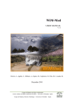
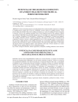
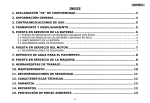
CEL-30
CEL-35
CEL-42
CEL-45
E-2
ENGLISH
2-
ENGLISH
INDEX
E-2 ................................................................................................................ 1
1. GENERAL INFORMATION ........................................................................... 4
2.
GENERAL DESCRIPTION .......................................................................... 4
2.1 TRANSPORT ............................................................................................................ 5
2.2 PICTOGRAMAS. ........................................................................................................ 5
3. ASSEMBLING INSTRUCCIONS .................................................................... 5
3.1 MOUNTING THE BLADES ............................................................................................ 5
3.2 REPLACING AND TIGHTENING THE BELTS...................................................................... 6
3.3 MAINTENANCE, INSPECTION AND CONTROL .................................................................. 6
4. STARTING UP AND USING THE MACHINE ................................................... 6
5. SOLUTIONS TO MOST FREQUENT ANOMALIES ........................................... 7
6. TECHNICAL CHARACTERISTICS ................................................................. 7
6.1 CUTTING CHARACTERISTICS TABLE ............................................................................. 8
7. ELECTRICAL SCHEME ................................................................................. 8
7.1
ELECTRICAL CONNECTION ..................................................................................... 8
7.2 SAFETY RECOMMENDATIONS ...................................................................................... 9
8. WARRANTY.............................................................................................. 10
9. SPARE PARTS .......................................................................................... 10
10. DECALARATIONS ON NOISE................................................................... 10
11. DECLARATIONS ON MECHANIAL VIBRATIONS ....................................... 10
12. ENVIRONMENT PROTECTION ................................................................. 10
WARRANTY CERTIFICATE ............................................................................ 13
3-
ENGLISH
1. GENERAL INFORMATION
WARNING: Pease read and understand perfectly the present instruction before using the machine.
SIMA S.A. thanks you for your trust in our products and for purchasing the ELECTRICAL SHEAR model CEL.
This manual provides you with the necessary instructions to start, use, maintain and in your case, repair of the
present machine. All aspects as far as the safety and health of the users is concerned have been stated. Respecting
all instructions and recommendations guarantees safety and low maintenance. As such, reading this manual carefully
is compulsory for any person responsible for the use, maintenance or repair of this machine.
It is recommended to have always this manual in an easily accessible place where the machine is being
used.
2. GENERAL DESCRIPTION
SIMA S.A., ELECTRICAL SHEAR model CEL, have been designed and manufactured to be used in work sites to
cut steel reinforced and flat bars for construction, using interchangeable blades, mounted onto the cutting jaws.
Any other use of the machine is considered inadequate and can cause danger. Therefore, it is expressively
prohibited.
•
The manual shear model CEL has been designed and manufactured to cut flat and reinforced steel bars used
for construction and passive steel armatures for structural concrete by means of two interchangeable blades
mounted onto the cutting jaw.
•
The cutting operation is done manually by pushing the bar on the roller, dropping the bar into the cutting
throat, lowering the protection guard and pressing the pedal.
•
The CEL models are furnished with a ring to elevate the machine.
•
The machine is equipped with wheels and handlebars to facilitate their movement and transport for short
distances.
•
The internal mechanical components that are subject to wearing have been treated thermally to guaranty
their long durability and high performance.
•
The main body of the machine is a mono-block made of cast iron.
•
Cutting is performed by means a pedal or a handlebar.
•
The blades are rectangular with four cutting faces.
•
Internal mechanisms are bathed in oil.
•
The frame of the machine is painted in oven with a highly resistance, anti-corrosion epoxy polyester paint.
•
The electrical equipment of the machine complies with the EC safety norms.
4-
ENGLISH
2.1 TRANSPORT
For a safe transport of the machine, please follow the following instructions:
The Electrical Shear is fitted with holes on the working table to be lifted with cranes through chains or cables. The used
means of transport must be safe, taking into account the form of use, the nature of the load.
WARNING: Keep away from the lifted load and be careful of its sudden displacement to avoid any possible danger
during transportation, moorage, charging or discharging. Therefore the choice of the correct of the cable, chain and
sling is fundamental.
The electrical shears are equipped with a ring B, Fig.2 for its lifting or transport. The CEL models have also a
transport handlebar A, Fig.2 to move it for short distances.
IMPORTANT : During the transport of the machine, the latter should never be reversed nor be put on either
side. The machine is only to rest on its four feet Fig. 2.
2.2 PICTOGRAMAS.
Pictograms included in the machine entail the following:
USE HELMET AND EYE AND EAR
DEFENDERS
READ
INSTRUCTIONS
MANUAL
USE SAFETY GLOVES
USE SAFETY FOOTWEAR
3. ASSEMBLING INSTRUCCIONS
The machine is delivered mounted and prepared to operation.
3.1 MOUNTING THE BLADES
If one of the blades gets blunt due to frequent use, replace it as follows:
1
CHANGING THE FIXED BLADE. Make sure the machine is unplugged from electricity. Lift the safety
guard off the blades A, Fig.3 taking it out from its housing. Remove the protection B, Fig.3 fixed to the
left side of the machine to have access to the screws of the blades, remove the screws C, Fig.3 and
rotate the blade D, Fig.3 for a new set of cuttings or substitute it with a new blade if necessary.
2
CHANGING THE MOVEABLE BLADE. To do this, it is necessary to remove the connecting rod from its
housing E, Fig.3, and then proceed as to the following: when the machine is put on, switch it off by
pressing the stop button. While de flywheel is making its last turns, press the pedal to push the
connecting rod from its housing to have access to screws fixing the blades F, Fig.3. Immediately
thereafter, unplug the machine off the network to avoid accidents. If the connecting rod is not out of its
housing, turn gently the flywheel from the inferior part of the safeguard that covers the engine until the
connecting rod is out of its housing, and then remove the screws off the blade for a new cutting face or
replace it with a new one if necessary. At the end, proceed to the inverse to restore the operation of the
machine.
The screws are to be tightened with a torque wrench as per the following:
3
CEL-30----------- 25,07Nm.
CEL-35/42------ 84,24Nm.
CEL-45----------- 135,13Nm.
5-
ENGLISH
3.2 REPLACING AND TIGHTENING THE BELTS
The machines leave the factory with the belts perfectly tightened. It is possible that due to the
incorrect machine installation or long use of the machine, the belts get loose. To tighten back the belt or replace it,
please consider the following steps (Fig.4).
1 Make sure the machine is unplugged off the power supply.
2 Remove the safeguard of the motor.
3 Loosen the tensor of the motor by means of the nuts A, B, C, and Fig.4
4 Replace or tighten the belt.
5 Once finished, proceed to the inverse.
6 Place the safeguard of the motor back.
Important: Never work with the motor safeguard while the transmission is removed, as this can
cause serious accidents.
3.3 MAINTENANCE, INSPECTION AND CONTROL
To keep the shear in good conditions, you need to check periodically the following points:
1 Check periodically (each 40 hours of use) the efficiency of the blades and if necessary to replace them,
proceed as per the instructions manual.
2 Check (monthly) the level of oil with the visor B, Fig.5 y 5.1 and fill up if the level is below the stopper A,
Fig.5 y 5.1. It is recommended to change the oil every two years.
TABLE OF OIL EQUIVALENCES ACCORDING TO MANUFACTURERS
Manufacturers
TYPE OF OIL
CEPSA
ENGRANAJE-HP 320
SHELL
OMALA 320
ESSO
SPARTAN EP-320
REPSOL
SUPERTAURO 320
3 Grease (every 100 hours of use) the connecting rod by the nipple F, Fig. 5.1 with consistent grease. The
CEL-45 model has another point of lubrication with oil on top of the greasing of the connecting rod D, Fig. 5.1, which
needs to be lubricated with the same oil that arrives to the reducer box, at this point of greasing, we lubricate the
bronze bearing.
4 Check the state and the tension of the transmission belts. The latter is supposed to be always tight to avoid
any sliding, which can cause a mal functioning of the machine.
5 All electrical or interior components installations are recommended to be effectuated by authorized people.
6 At the end of each day, unplug the machine.
7 If the machine is not covered, wrap it with impermeable cloth.
8 Clean periodically the visible parts of the machine and grease as necessary.
WARNING: Before performing any maintenance or cleaning, the power supply cable needs to be
unplugged.
4. STARTING UP AND USING THE MACHINE
WARNING: All safety recommendations must be followed, either the ones mentioned in the present user manual or
those complying with all labour risks prevention norms in every location.
WHEELWORK: SIMA CEL models do not need any wheelwork operations as they are specially designed to obtain the
maximum performance from start.
NORMAL USE OF THE MACHINE:
The electrical shears have been designed to cut flat and reinforced steel bars for use in the structure and
other construction components is in conformity with all applicable provisions of the Directive of Machines (98/37/CE)
and the national applicable regulations . Each other use that has not been expressively indicated is considered
abnormal. Any tool or accessory added or amended without written authorization from the manufacturer is considered
inappropriate and dangerous. If any damage or injury is caused as a result thereof or by misuse of the machine, SIMA
S.A. exempts all responsibility as manufacturer. The machine must be installed on a plane, firm and horizontal surface
and the ground should not be soft. This machine DOES NOT HAVE TO BE USED UNDER THE RAIN. ALWAYS
WORK IN WELL ILLUMIINATED AREAS.
6-
ENGLISH
STEPS TO FOLLOW TO REALISE A CUTTING
1 Lift slightly the blades safeguard to save height of the flange and then drag it completely leftwards Fig.6
before you can lift it totally.
2 Resting the bars upon the roller so that you can easily move the bar forward as per the predetermined
measurement. Place the bar in the throat between the two blades. Lower back the blades safeguard and pus hit
rightward to free the pedal (the mechanism that operates the cutting).
Note: CEL models are equipped with a safety system that when the blades safeguard is lifted, the blades would not
be able to cut the material.
3 Once the safeguard has been released, we can effectuate a cutting, either by pressing the pedal or pulling
the grip.
Never try to make a cut while the safeguard is lifted as the material to cut can leave the cutting throat and
cause damage.
5. SOLUTIONS TO MOST FREQUENT ANOMALIES
ANOMALY
POSSIBLE CAUSE
Fault of the electrical power supply
Motor does not start
SOLUTION
Check the power supply in the switch
board. Check the position of the circuit
breaker and the residual current device
in the switch board.
Make sure the extension cable is in good
state and its fitting in the two extremes is
correct.
activation of the thermal protection of Wait until the motor has cooled down
the single-phase switch
and re-activate the thermal protection
Switch damaged
Motor starts very slowly and takes too Condenser damaged.
long to reach its revolutions
(Single-phase motors)
Cutting power is too low
Premature wearing of the belts
Replace it
Replace it
Belt loose or blunt
Tighten the belt or replace it
Blades blunt
Change the cutting face of the blade
or replace it
Power drop down of the motor
Let the technical service check the
motor.
The belts slide over the pulleys
Tighten the belts
6. TECHNICAL CHARACTERISTICS
7-
ENGLISH
6.1 CUTTING CHARACTERISTICS TABLE
7. ELECTRICAL SCHEME
CEL-30, 35, 45.
7.1 ELECTRICAL CONNECTION
The extension cable used to feed the machine needs to have a minimum section of 4x2.5 mm2 up to 25
meters long. For a superior distance 4x4 mm2 can be used. In one of its ends, it is needed to connect a base
normalised aerial of 3P+T or 3P+N+T compatible with the machine switch and in the other end, one normalised aerial
pin of 3P+T ó 3P+N+T compatible with switchboard exit.
Machines with electrical motor should always be connected to a normalised switchboard that disposes of a
magneto-thermal switch and a differential in accordance with the characteristics of the motor:
3Kw /4 CV, three phase at 400V, 15A magneto-thermal and 15A/30mA differential.
4Kw / 5.5 CV, three phase at 400V, 10A magneto-thermal and 10A/30mA differential.
The machine electrical tension is visible on the voltage indication next to the top of engine terminals and on the
machine characteristics plate.
WARNING: Do not plug the machine to the electricity if you are not sure of the available electrical tension.
If the tension is not correct, the engine will undergo irreparable harm or out of service.
WARNING: Never manipulate the power cables or any electrical equipment of the machine, if you have not
totally unplugged the machine from the electricity.
Once you have brought the rotation direction of the engine back, the machine is ready to operate.
IMPORTANT: It is appropriate to change the position of the bridge plates in the engine terminals. It is also important
to change the adhesive labels indicating the voltage, to reflect the change made.
8-
ENGLISH
7.2 SAFETY RECOMMENDATIONS
The electrical shears models CEL are to be used by trained people or people familiarized with their operation.
•
Before starting up the machine please read the instructions and make sure safety norms are
respected. Learn how to stop the machine in a fast and safe way.
•
Place the machine on a plane surface. Connect the machine to the electricity only when you are sure
of its stability.
•
Start the machine only when you have mounted the safety guards that come with the machine.
•
It is recommended to use safety glasses, safety boots, gloves etc. Please always use approved
materials.
•
Always use Individual Protection Equipment (IPE) in accordance with the type of work you are
effectuating.
•
Prohibit strangers to access the place of work of the machine.
•
Work clothes are not supposed to have loose articles that can cling into movable parts of the
machine.
•
When you have to move the machine, unplug the electricity cables and block the moving parts of the
machine.
•
Always keep protection elements and the safety guards in their correct positions.
•
The damaged electrical cables should be urgently replaced.
•
Make sure the rotation sense is correct.
•
Unplug the machine from the electricity and never manipulate nor operate on the mechanical nor
electrical elements of the machine while the engine is on.
•
Visually control the joints, bolts, nuts, wildings, corrosion, etc.
•
Never leave the machine with the engine switched on.
•
Never use the machine for purposes other than those it has been designed for.
VERY IMPORTANT: Always use earth plug before starting-up the machine.
• Use normalised cables
• Make sure the feeding voltage is in accordance with the voltage indicated in the adhesive label on the machine.
• Make sure that the extension cords are not in contact with points of high temperature, oil, water, sharp edges.
Also avoid trampling or crushing the cables by passing vehicles and do not put any objects on the machine.
• Do not use high pressure water to clean circuits or electrical elements.
ATTENTION: You are to follow all safety recommendations mentioned in the present user manual and comply with
all labour risks prevention norms in every location.
SIMA, S.A. is not responsible for the consequences possibly generated but the inadequate use of the bending or the
electrical shear, models CEL.
9-
ENGLISH
8. WARRANTY
SIMA, S.A. the manufacturer of light machinery for construction possesses a net of technical services “SERVISIMA”.
Repairs under warranty made by SERVÍ-SIMA are subject to some strict condition to guaranty a high quality
and service.
SIMA S. A. guarantees all its products against any manufacturing defect; to take into account the conditions stated in
the attached document “WARRANTY CONDITIONS”. The latter would cease in case of failure to comply with the
established payment terms. SIMA S.A. reserves its right to bring modifications and changes to its products without
prior notice.
9. SPARE PARTS
The spare parts for the bending and combined machines, manufactured by SIMA, S.A. are to be found in the
spare parts plan, attached to this manual.
To order any spare part, please contact our alter-sales service clearly indicating the serial number of the
machine, model, manufacturing number and year of manufacturing that show on the characteristics plate.
10. DECALARATIONS ON NOISE
The acoustic levels emitted by the MACHINE are inferior to 70 dB (A)
11. DECLARATIONS ON MECHANIAL VIBRATIONS
The machine does not present any source of mechanical vibrations that cause risks to the health or safety of
the operator.
12. ENVIRONMENT PROTECTION
Raw materials have to be collected instead of throwing away residuals. Instruments, accessories, fluids
and packages have to be sent into specific places for ecological reutilisation. Plastic components are
marked for selective recycling.
R.A.E.E. Residuals arising of electrical and electronic instruments have to be stored into
specific places for selective collection.
10-
ENGLISH
11-
ENGLISH
12-
ENGLISH
WARRANTY CERTIFICATE
AFTER-SALES SERVICE
END USER FORM
MACHINE DETAILS
NUMBER PLATE
CLIENT DETAILS
NAME
ADDRESS
POSTAL CODE AND CITY
PROVINCE/COUNTRY
TEL.:
Fax:
E-mail
DATE OF PURCHASE
Signature and stamp of the selling party
Client signature
WARRANTY CONDITIONS
1.) SIMA, S.A. fully guarantees all its products against defects in design, taking responsibility in the repairs or the faulty equipment for a period of ONE year
from the original date of purchase. The date of purchase must appear on the warranty voucher enclosed.
2.) The warranty covers exclusively labour, repair and substitution of the faulty parts, the model and serial number of which must show on the warranty
certificate.
3.) Transport, stay and food expenses before arriving to SIMA S.A., will be covered by the client.
4.) The warranty does not cover any damage caused by the normal wear, undue usage, overloading, inadequate installation or bad conservation of the
machine.
5.) All repairs under WARRANTY will solely be effectuated by SIMA, S.A. or by its authorised dealers or repair centres.
6.) This Guarantee will be invalid in the following cases:
a) Any Warranty certificate manipulation or modification
b) Repairs, modifications or substitution of any part of the machine by unauthorized parties by SIMA S.A technical department.
c) The non-approved installation of devices by SIMA S.A technical department.
7.) SIMA is not responsible for any damages caused by the failure of the product. This includes, but not limited to, annoyances, transport expenses, telephone
calls and loss of personal goods or commercial benefits, as well as the loss of pay or salary.
8.) Faulty thermal or electrical motors under warranty have to be sent to SIMA S.A or its authorized technical service in the country.
9.) To be benefit from the warranty, the warranty certificate must be at SIMA S.A premises within 30 days from the purchasing date. To claim the warranty,
the purchase invoice has to be attached stamped by the dealer including the serial number of the machine.
SOCIEDAD INDUSTRIAL DE MAQUINARIA
ANDALUZA, S.A.
POL. IND. JUNC ARIL, C /ALBUÑOL, PARC . 250
18220 ALBOLOTE (GR ANADA)
TEL: 34 - 958-49 04 10 – Fax : 34 - 958-46 66 45
MANUFFAC TRUR ER OF LIGHT MACHINERY FOR CO NSTRUC TIO N
SPAIN
13-
ENGLISH
WARRANTY CERTIFICATE
AFTER-SALES SERVICE
FORM TO RETURN TO MANUFACTRURER
DATOS MÁQUINA
NUMBER PLATE
DATOS COMPRADOR
NAME
ADDRESS
POSTAL CODE AND CITY
PROVINCE/COUNTRY
TEL.:
Fax:
E-mail:
DATE OF PURCHASE
Signature and stamp of the selling party
Client signature
WARRANTY CONDITIONS
1.) SIMA, S.A. fully guarantees all its products against defects in design, taking responsibility in the repairs or the faulty equipment for a period of ONE year
from the original date of purchase. The date of purchase must appear on the warranty voucher enclosed.
2.) The warranty covers exclusively labour, repair and substitution of the faulty parts, the model and serial number of which must show on the warranty
certificate.
3.) Transport, stay and food expenses before arriving to SIMA S.A., will be covered by the client.
4.) The warranty does not cover any damage caused by the normal wear, undue usage, overloading, inadequate installation or bad conservation of the
machine.
5.) All repairs under WARRANTY will solely be effectuated by SIMA, S.A. or by its authorised dealers or repair centres.
6.) This Guarantee will be invalid in the following cases:
a) Any Warranty certificate manipulation or modification
b) Repairs, modifications or substitution of any part of the machine by unauthorized parties by SIMA S.A technical department.
c) The non-approved installation of devices by SIMA S.A technical department.
7.) SIMA is not responsible for any damages caused by the failure of the product. This includes, but not limited to, annoyances, transport expenses, telephone
calls and loss of personal goods or commercial benefits, as well as the loss of pay or salary.
8.) Faulty thermal or electrical motors under warranty have to be sent to SIMA S.A or its authorized technical service in the country.
9.) To be benefit from the warranty, the warranty certificate must be at SIMA S.A premises within 30 days from the purchasing date. To claim the warranty,
the purchase invoice has to be attached stamped by the dealer including the serial number of the machine..
SOCIEDAD INDUSTRIAL DE MAQUINARIA ANDALUZA, S.A.
POL. IND. JUNC ARIL, C /ALBUÑOL, PARC . 250
18220 ALBOLOTE (GR ANADA)
TEL: 34 - 958-49 04 10 – Fax : 34 - 958-46 66 45
MANUFFAC TRUR ER OF LIGHT MACHINERY FOR CO NSTRUC TIO N
SPAIN
14-
ENGLISH
15-
ENGLISH
16-
SOCIEDAD INDUSTRIAL DE MAQUINARIA ANDALUZA, S.A.
POL. IND. JUNCARIL, C/ALBUÑOL, PARC. 250
18220 ALBOLOTE (GRANADA)
TEL..: 34 - 958-49 04 10 – Fax: 34 - 958-46 66 45
MANUFACTURER OF LIGHT MACHINERYY FOR CONSTRUCTION
SPAIN