1
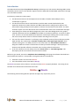
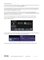
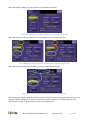
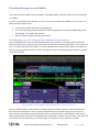
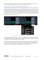
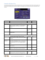
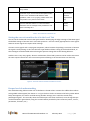
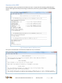
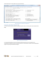
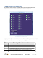
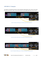
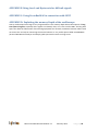
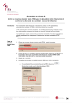
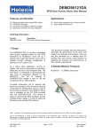
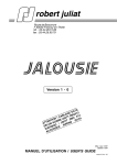
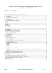
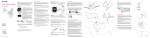
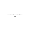
SENT Decoder, Documentation for Release 7.1 Lahniss Sarl, February 2013 Table of Contents SENT Decoder, Documentation for Release 7.1 .............................................................................................. 1 Table of Contents ........................................................................................................................................ 1 List of Figures ............................................................................................................................................... 2 Introduction ..................................................................................................................................................... 3 Getting started ................................................................................................................................................ 4 Decoding Messages as raw Nibbles................................................................................................................. 6 Verifying the correct settings of the fundamental parameters .................................................................. 6 Using the zoom to rapidly verify the initial decoding.................................................................................. 7 Controls of the Basic Tab ............................................................................................................................. 8 Setting the correct transition level in the Level Tab ................................................................................... 9 Deeper level of understanding .................................................................................................................... 9 Decoding Fast Channels as Words................................................................................................................. 11 Controls of the Fast Channel Tab (governing the Word decoding) ........................................................... 12 Using the Fast Channel tab to verify Secure Sensors decoding ................................................................ 12 Decoding the Slow Channel ........................................................................................................................... 13 Switching the decoder to view the Slow Channel ..................................................................................... 13 Creating and Editing the Slow Channel Definition File (SCDF) .................................................................. 14 Structure of the SCDF ................................................................................................................................ 15 Controls of the Slow Channel Tab ............................................................................................................. 16 Columns Contents of the Decode Table ........................................................................................................ 17 APPENDIX A 3 Examples ................................................................................................................................ 19 APPENDIX B Using Level and Hysteresis for difficult signals ......................................................................... 20 APPENDIX C: Using ProtoBusMAG in connection with SENT ........................................................................ 20 APPENDIX D: Exploiting the memory Depth of the oscilloscope................................................................... 20 Manual for SENT Decoder Release 7.1 February 2013 Page |1 List of Figures Figure 1: The selection of SENT in the Decode Setup ..................................................................................... 4 Figure 2: The protocol selection governs the appearance of the Right Hand Side tabs. ................................ 4 Figure 3 When Decode Type is Nibble, only the Basic and Levels tabs are required ...................................... 5 Figure 4 When either Fast Only or Slow Only is selected, the corresponding tab will appear ....................... 5 Figure 5 When Channels = Both are selected, Fast and Slow tabs will be shown........................................... 5 Figure 6 Example of correct Nibbles decoding with Mother Trace, Zoom and Basic Tab............................... 6 Figure 7 How to "Play" through every decoded packet of the record ............................................................ 7 Figure 8: The Basic Tab and its Controls .......................................................................................................... 8 Figure 9: The Level controls and there visualization on trace ......................................................................... 9 Figure 10: The D0 column shows the raw nibble values, here in Decimal, for 8 nibbles. ............................. 10 Figure 11: SENT message #20 decoded with its Status and CRC nibbles only, no Fast Channel used .......... 11 Figure 12: Same SENT message #20 with Payload Words interpreted, as 2x3 nibbles................................. 11 Figure 13 Slow Channel Only Decode ............................................................................................................ 13 Figure 14 Interpretation of the Slow Messages using the SCDF file ............................................................. 14 Figure 15 Example of SCDF for a Melexis P/T sensor .................................................................................... 15 Figure 16 Syntax error emitted by the SCDF Parser ...................................................................................... 16 Figure 17 Slow Channel Tab controls ............................................................................................................ 16 Figure 18: The columns of the SENT decoder ............................................................................................... 17 Figure 19: Example of SENT signal, 3us TickTime, Idle Low with Pause Pulse .............................................. 19 Figure 20: Example of SENT signal, 12 us TickTime, Idle high with Pause Pulse ........................................... 19 Figure 21: Example of SENT signal, 3us Tick Time, Idle High, without Pause Pulse ...................................... 19 Manual for SENT Decoder Release 7.1 February 2013 Page |2 Introduction The SENT Decoder developed by Lahniss for LeCroy oscilloscopes is a tool aimed at decoding SENT stream emitted by various sensors. This decoder supports both the 2008 and the 2010 SENT specification through User selectable variables. Introductory comments to the manual. This document relies on the assumption that the reader is familiar with Teledyne LeCroy oscilloscopes in general. This document also assumes some familiarity with the SENT standard published by SAE. Experience shows that readers familiar with NRZ or Manchester coding need to adjust to the Pulse width coding technique used by SENT to transmit the Fast Channel Information. The Slow channels require one more abstraction level: the distribution of bits over several SENT messages. Some dialogs are shown with black backgrounds, other with violet backgrounds. This graphic method emphasizes the fact that SENT D is available on all xStream platforms, as well as on older units. There are no functional differences between oscilloscopes showing tabs in violet or black, the color merely reflects shifts in industrial fashion and design over the years. The use of the word “Channels” is confusing in the combined context of the oscilloscope and the SENT decoder. On oscilloscopes, channels normally refer to the signal input channels, often called C1 through C4. The SENT protocol on the other hand uses Fast and Slow channels to designate 2 different streams of information carried by the SENT messages. We hope that the document will provide sufficient contextual clues to always allow the distinction. In all of the document screen dumps show the “Pause Pulse” as “Inter Message Gap” This discrepancy will be corrected in the next firmware release. Before we get started, we need to emphasize the methodology underlying the software described here. The fundamental model is a 3 step model. The signal needs to be decoded as: Each Burst needs to be sliced into Nibbles Then the nibbles can be converted to Word(s) The Words extraction will not function correctly until the Nibbles properly decoded. The tuning of the Decoder must therefore be conducted in this order: Nibbles Words. The following material will guide the operator through every step of the process. Manual for SENT Decoder Release 7.1 February 2013 Page |3 Getting started In order to get started with the SENT Decoder, it is advisable to adjust the scope controls to acquire 5 to 8 Burst or Frame of relevant Data, and then stop the acquisition. Once the SENT messages are acquired, we will proceed to its interpretation using the SENT Decoder. We will proceed gradually; starting with the identification of the Burst controls, then extract the Nibbles and finally the Words, by grouping nibbles into Words. Later we will address the decoding of many Packets into the same record, therefore allowing the observation of the encoded data values over a period of time. The decoder settings determined on a few packets will be reused when handling many packets. In order to start the decoding we need to be familiarized with the User Interface of the Decoder. Firstly, in the Serial Decode dialog, you need to select the signal source (here Memory 1), and the Protocol, “SENT” in this case. Figure 1: The selection of SENT in the Decode Setup Once the “SENT” Protocol has been selected 2 to 4 tabs will appear in the Right Hand Side Dialog. We will be setting various values in these 3 tabs: Basic, Fast Ch, Slow Ch and Levels Figure 2: The protocol selection governs the appearance of the Right Hand Side tabs. The Right Hand Side tabs composition is governed by selections in the Basic tab, as explained below. Manual for SENT Decoder Release 7.1 February 2013 Page |4 When decoding by Nibbles, the tabs only have one possible incarnation. Figure 3 When Decode Type is Nibble, only the Basic and Levels tabs are required When decoding as Words, the selection of tables depends on the Channels selection. Figure 4 When either Fast Only or Slow Only is selected, the corresponding tab will appear When decoding as Words, Channels=Both, all of the 4 tabs will be presented. Figure 5 When Channels = Both are selected, Fast and Slow tabs will be shown When working on a given signal, some of the values in the tabs will not change anymore because they are strongly linked to the signal (i.e. Tick Time or Idle State). Other values can or will have to be tuned to obtain optimal results, or understand the reasons for misbehaviors. Manual for SENT Decoder Release 7.1 February 2013 Page |5 Decoding Messages as raw Nibbles As its name indicates, SENT is based on Nibbles and Nibble length. Therefore the first level of decoding is the nibbles. In order to start adjusting the decoder, it is best to select the Decode Type “Nibbles” In this mode every SENT Packet will appear, with: its SYNC (also named CAL) pulse at the beginning. its 5 to 8 constituting nibbles, labeled with values ranging from 0 through 15, depending on the pulse length, as per SENT specifications. the Inter Frame Gap (IFG) between the packets . Verifying the correct settings of the fundamental parameters Every complete packet in the trace should be decoded, the Tck values in the table should be coherent with the TickTime set in the Basic Tab, and the IFG times should be within specifications. In this mode, it is easy to visually verify that every packet is correctly identified and outlined. There might be exception on the first and last packet of the trace, close to the edge of the grid. The following figure shows an example of correct decoding Figure 6 Example of correct Nibbles decoding with Mother Trace, Zoom and Basic Tab The first rapid validation can be visual, by randomly looking at different portions of the decoded trace. The trace can be assessed, so that it is firmly established that the decoder setting are correct for the signal at hand. In principle, as long as the signal source remains identical ( measuring on same sensor), this procedure does not need to be repeated. When measuring on different sensors of the same type, and parameterized in the same way, the same settings can usually be re-used. However, the SENT Manual for SENT Decoder Release 7.1 February 2013 Page |6 specification allows large variations of the TickTime. So it is possible that similar sensors built over the years from successive fabrication batches and wafers differ from one another. Using the zoom to rapidly verify the initial decoding The zoom allows a more systematic verification of the decoding, explained here. Once the decoding is in engaged, the Table appears below the grid. When starting on a new signal, it is often useful to make sure the fundamental parameters (TickTime, Polarity and Levels), are selected correctly. By clicking into the first columns (Line Index), a zoom of the trace corresponding to the selected line will appear, for example the next Fig shows the zoom of line 21 (of the table) in Z4. The zoom is a precious tool when studying a decoded trace because every packet can be rapidly analyzed. When clicking on the Zoom descriptor, the Zoom and Search controls appear as below. Figure 7 How to "Play" through every decoded packet of the record The image above highlights the procedure. First select the Framing of the zoomed packets by adjusting the Left/Right padding. A 100% padding means that a full message length will be added right and left of the message zoomed at when clicking on any line of the table. Then jump to the very first decoded packet in the records by pushing 1. Then, push 2 to “Play” through the entire record, jumping from one packet to the next, at a rate of approximately 1 image/second. Watch the packets while the play continues and make sure that the decoding is consistent with your expectations. For the time being we are not looking at the nibbles values at all. Manual for SENT Decoder Release 7.1 February 2013 Page |7 Controls of the Basic Tab As intuitively shown above, we will now describe every control of the Basic Tab. These controls govern all of the basic decoding, and let the user adjust the decoding to the fundamental protocol parameters and version. Figure 8: The Basic Tab and its Controls UI control Function Range Default Viewing Decode Type Changes the way the signal is decoded, in terms of details and depth of decoding. It is recommended to start with Nibbles, then move on to Words when needed. Nibbles, and Words Nibbles Channels Selection of the SENT channels to be processed. Fast Only, Slow Only or both Fast Only Format Viewing format of the Nibble values and D0 through D3 data values. Hexadecimal or Decimal Hexadecimal Physical Layer Tick Time Controls the SENT Ticktime, which is the Time increment between a nibble of value N and a nibble of value N+1 400 ns to 3 ms 3 us Tick Time Tolerance Defines how the CAL pulse is filtered with respect to the Ticktime indicated by the user. i.e. if a tick Time of 3us is set, with a tolerance of 10% the CAL pulse is expected to be 56 * 3 us +- 10%, therefore 168 us +10% 1 % to 30% 10% Idle State Defines where the idle state lies, therefore opposite of pulse direction. High or Low High Nibbles The number of nibbles contained in a single SENT message, including Status, Data and CRC nibbles. 5 or 8 8 2008 or 2010 2010 Protocol Details SENT Version Selection between the 2008 and 2010 Version. In the 2008 Version CRC and Pause Pulse are turned off and grayed out since they are not supported. In the Manual for SENT Decoder Release 7.1 February 2013 Page |8 2010 Version both controls are available, and turned on by default. New CRC When checked, the CRC computation will be performed as per 2010 recommended implementation under 5.4.2.2. Otherwise it will follow the 2008 guidelines, under 5.4.2.1 (Legacy). Note that the CRC computation is only active in Word mode. On/off On (recommend ed 2010 implementati on) Pause Pulse When checked, algorithm expects a Pause pulse as per 2010 definition under 5.2.6. The Pause Pulse follows the CRC of message N and precedes the CAL pulse of message N+1 On/Off On (with Pause Pulse) Table 1: List of Controls in the Basic Tab Setting the correct transition level in the Level Tab The last tab of the decoder controls the levels used for determining the edge crossings of the SENT signal. The default settings of Percent level = 25% and Hysteresis = 15% are usually appropriate for most signals. However certain signals can require other settings. A known case is signals with a varying DC component, either because the probing is incorrect or because the signal is really floating. In this case the level Type Absolute allows a fixing of the threshold level, so that messages can be decoded without having the dynamic change due to the floating behavior. Another case is very noisy signals, where a combination of level and hysteresis can be used to overcome the noise impact. Note that in this case some upstream filtering in the channel menu can also help. Figure 9: The Level controls and there visualization on trace Deeper level of understanding This nibble decoding allows another set of validations. The D0 column contains the nibble values. When wrong nibble values appear (less than 0 or > 15) just click on the line to examine the faulty packet. When faulty data appears, the reason could be wrong decoder settings, but it could also reveal really pathological signals. This is usually when the oscilloscope is the most useful tool, since the signal shape can be examined in great details, using the normal toolbox provided by the instrument (zooms, cursors, parameters, functions, etc.) Manual for SENT Decoder Release 7.1 February 2013 Page |9 Figure 10: The D0 column shows the raw nibble values, here in Decimal, for 8 nibbles. The image above shows an example of healthy decoding. Note that users of oscilloscopes with an orientable screen can rotate the screen and expand the table to the maximum number of lines to have a better overview of the complete decode. Manual for SENT Decoder Release 7.1 February 2013 P a g e | 10 Decoding Fast Channels as Words Once the decoding as nibbles yields satisfying result, the decoding as Words can be switched on by simply switching the Decode Type to “Words”. The SENT packets will be further analyzed to interpret the nibbles in the context of the SENT protocol structure. For the sake of clarity we will switch on the Word mode and show a SENT message with only its infrastructure nibbles, SYNC and Pause Pulse. The first nibble represents the Status (red) and the last nibble the CRC (blue) whilst the remaining nibbles in the middle will carry the payload of the message. For the sake of explanation a message is shown here, only with the infrastructure nibbles. Figure 11: SENT message #20 decoded with its Status and CRC nibbles only, no Fast Channel used The same message, with the payload nibbles interpreted as words, appears in the following commented image, also showing the setting of the Fast Channel. This dialog drives the interpretation of all the nibbles, except the Status and CRC nibbles. Figure 12: Same SENT message #20 with Payload Words interpreted, as 2x3 nibbles The Fast Channel dialog allows the user to select the grouping of the nibbles (4 bits) into 4, 8, 12,16,20,24 bit words. This information transportation method helps carrying many bits with a minimum number of transitions. As shown in the dialog, the user is free to select any offset and any number of nibbles to form Manual for SENT Decoder Release 7.1 February 2013 P a g e | 11 the words. Some sensors broadcast information as 2 x 12 bits for Pressure and temperature. Other sensors emit Pressure with 12 bits, a running counter with 8 bits and the invert of the most significant Nibble with 4 bits. Other sensors might emit only 16 or 24 bit value. Any of these combinations can be accommodated by the algorithm. Furthermore, the CRC nibble validates the encoding/decoding of the Frame. Should a Frame have a bad CRC, its line in the table would present a warning message “CRC error”. A bad CRC can have many reasons originating in the signal transmitter hardware or software, the transmission lines or the receiver. Controls of the Fast Channel Tab (governing the Word decoding) Using the Fast Channel tab to verify Secure Sensors decoding Manual for SENT Decoder Release 7.1 February 2013 P a g e | 12 Decoding the Slow Channel SENT provides a creative mechanism to broadcast information that was usually to be found in data sheets, specifications and other auxiliary literature, such as conversion coefficients from raw data to physical values, manufacturer’s name, type of sensor, etc. This mechanism relies on 2 bits in the Status & Communication Nibble of the SENT message. These bits are fetched from 16 or 18 adjacent messages and grouped to form a Message ID, a message Value and a CRC. Switching the decoder to view the Slow Channel The following image shows what happens when switching the Channels to “Slow Only” mode. The annotation is modified and groups messages into chunks of 16 or 18 messages, depending on which version of SENT is used. Figure 13 Slow Channel Only Decode The decode Table dynamically changes its contents to reflect the new situation. The time columns shows the beginning of each slow message. The “Msg” columns show the decoded Name and value of the slow message. D0 restitutes the Message ID and D1 show the Message value. Other columns are not used in this mode. As visible on the image, names and values of the messages currently set to default values: Manual for SENT Decoder Release 7.1 February 2013 P a g e | 13 *+8b Msg 5 means “default value for 8 bit message ID number 5” *+Manufacturer 11 means “default value for Manufacturer value 11” *+ Diagnostic 0 means “default value for Diagnostic value 0” We will see in the next section how the default values can be changed and loaded into the decoder by means of a user constructed file. Before we move on to this file, also note the blue colored background of the slow messages. This will become significant when the Channel Mode “Both” is used, so that we can distinguish the Fast and Slow Messages. Creating and Editing the Slow Channel Definition File (SCDF) We will now explain how to enhance the decoding of the slow messages using the Slow Channel Definition File mechanism. Before we go into details, let’s look at the resulting evolution of the Slow Only decode mode. Figure 14 Interpretation of the Slow Messages using the SCDF file The image shows that the default Message IDs are transformed into real text and some of the values into text (Like “Manufacturer’s code = Melexis”) or values (such as Y position On Wafer = 22) The image also shows the “Slow Ch” dialog containing the name and path of the SCDF used to convey the Message Labels, Diagnostic Labels, as well as some other ancillary values such as Manufacturer’s codes and SENT revision number. Manual for SENT Decoder Release 7.1 February 2013 P a g e | 14 Structure of the SCDF The mechanism used to translate IDs and values into text is a simple TXT file containing table definitions. The file used to generate the previous image is shown here, with line 7,8,9,10 modified for the MLX90809 sensor. Figure 15 Example of SCDF for a Melexis P/T sensor The syntax is documented in the file itself, towards the end, as comments. Manual for SENT Decoder Release 7.1 February 2013 P a g e | 15 And the parsing errors are listed at the very end of the file. Figure 16 Syntax error emitted by the SCDF Parser Controls of the Slow Channel Tab The Slow Channel Tab only contains one filename picker control, containing the name and path of the SCDF Figure 17 Slow Channel Tab controls It is expected that different sensors will require different SCDF files, each one based on the manufacturer’s definition of the slow channel contents. A small common subset of the message space might end up being standardized messages. Manual for SENT Decoder Release 7.1 February 2013 P a g e | 16 Columns Contents of the Decode Table The table below explains every column of the table, and its meaning. Note that the table can be configured on the screen and columns can be turned on or off to help the operator. Figure 18: The columns of the SENT decoder As all the other settings in the scope the table can be configured remotely for Automated Test Equipment (ATE) on large test setups. The screen visibility of the column also drives the Export of the Table to a file. The table is always exported WYSIWYG (What you see is what you get) to the CSV file. Also refer to the general Serial Decode Manual more details on the export. Column s Meaning of the columns contents Idx Index of the line in the table, and also number of the message in the annotation. Time Time of the beginning of the SENT message, with respect to the trigger point of the record. Sync Real Measured Length of the Sync Pulse for the message on this line of the table. The pulse width is measured between the 2 falling edges of the Sync pulse, at the intersection of the signal and the Level selected in the “Level Tab” Note that large hysteresis also impact this value read out. Msg This is the message summary, with the number of transitions, nibbles and words. Manual for SENT Decoder Release 7.1 February 2013 P a g e | 17 Tck This is the Real TickTime value computed as the Sync pulse divided by 56. This value should be close to the selected TickTime in the Basic Dialog Stat The value of the Status and Communication Nibble. This value is also split into its bit components in the next 4 columns to help interpreting the contents (Status and slow channels). b0 Reserved for specific applications. b1 Reserved for specific applications. b2 Serial Data Message Bits (slow channels). b3 Message Start. D0-D3 The payload nibbles interpreted according to the settings of D0 in tab “Fast Ch”. This column only appears when D0 is active. These columns are also used for tracking values when using ProtoBusMAG. The D0 column is used when in Nibble mode CRC Value of the CRC nibble that gets compared to the computed value based on the other nibbles of the message. When these 2 values do not match, a message is emitted in the status column. It is normal that the first and last message of a record, when truncated, generate such a CRC error. rms Room Mean Square value of the falling edge crossings, usually in nanoseconds. 2 rms = /n n is so far always 8, for the 8 falling edges following the Sync pulse. So far values observed in the lab range from 10 to 50 ns, reflecting the local stability of the edge generations of the sensor. IFG Inter Frame Gap column, measured from the end of a message to the beginning of the next message. Status Error and Warning reporting column. Attributes Utility column, invisible to the user. Table2: List of Columns in the table Note: BitRate Tolerance is not used by the SENT decoder Manual for SENT Decoder Release 7.1 February 2013 P a g e | 18 APPENDIX A 3 Examples The images in the Appendix document various topologies of SENT signals, with a variety of Tick Times, Polarity and Pause Pulse. Refer to the main document for the detailed explanations of the controls. Figure 19: Example of SENT signal, 3us TickTime, Idle Low with Pause Pulse Figure 20: Example of SENT signal, 12 us TickTime, Idle high with Pause Pulse Figure 21: Example of SENT signal, 3us Tick Time, Idle High, without Pause Pulse Manual for SENT Decoder Release 7.1 February 2013 P a g e | 19 APPENDIX B Using Level and Hysteresis for difficult signals APPENDIX C: Using ProtoBusMAG in connection with SENT APPENDIX D: Exploiting the memory Depth of the oscilloscope LeCroy oscilloscopes have large or very large memories. This memory depth allows that capture of long time spans of signals, especially when signals are relatively slow, as it is the case for SENT. The long time spans can allow the observation of the message payloads over seconds, sometimes minutes. When used on sensors this can help in monitoring the sensors behavior. A very useful option called ProtoBusMAG (Protocol Bus Measure Analyze and Graph) yields spectacular results on long traces. Manual for SENT Decoder Release 7.1 February 2013 P a g e | 20