1
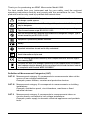
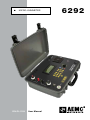
n
MICRO-OHMMETER
ENGLISH
User Manual
6292
Statement of Compliance
Chauvin Arnoux®, Inc. d.b.a. AEMC® Instruments
certifies that this instrument has been calibrated
using standards and instruments traceable to
international standards.
We guarantee that at the time of shipping your
instrument has met its published specifications.
An NIST traceable certificate may be
requested at the time of purchase, or obtained
by returning the instrument to our repair and
calibration facility, for a nominal charge.
The recommended calibration interval for this
instrument is 12 months and begins on the date of
receipt by the customer. For recalibration, please
use our calibration services. Refer to our repair
and calibration section at www.aemc.com.
Serial #: _________________________________
Catalog #: 2129.83
Model #: 6292
Please fill in the appropriate date as indicated:
Date Received: __________________________________
Date Calibration Due: ________________________
Chauvin Arnoux®, Inc.
d.b.a AEMC® Instruments
www.aemc.com
Thank you for purchasing an AEMC Micro-meter Model 6292.
For best results from your instrument and for your safety, read the enclosed
operating instructions carefully and comply with the precautions for use. These
products must be only used by qualified and trained users.
WARNING, risk of DANGER! The operator must refer to these instructions whenever
this danger symbol appears.
CAUTION! Risk of electric shock. The voltage at the parts marked with this symbol
may be dangerous.
Application or withdrawal authorized on conductors carrying dangerous voltages.
Type A current sensor as per IEC 61010-2-032.
Must not be applied to or removed from conductors at dangerous voltages. Type B
current sensor as per IEC 61010‑2‑032.
Equipment is protected by double insulation.
Battery
Important instructions to read and to fully understand.
Useful information or tip to read.
The CE marking guarantees conformity with European directives and with regulations covering EMC.
The trash can with a line through it means that in the European Union, the product
must undergo selective disposal for the recycling of electric and electronic material,
in compliance with Directive WEEE 2002/96/EC.
Definition of Measurement Categories (CAT)
CAT IV Measurement category IV corresponds to measurements taken at the
source of low-voltage installations.
Example: power feeders, counters and protection devices.
CAT III Measurement category III corresponds to measurements on building
installations.
Example: distribution panel, circuit-breakers, machines or fixed
industrial devices.
CAT II Measurement category II corresponds to measurements taken on
circuits directly connected to low-voltage installations.
Example: power supply to domestic electrical appliances and portable
tools.
Micro-ohmmeter Model 6292
1
Precautions for Use
The protection obtained by the instrument can be compromised if it is used in a
way that is not recommended by the manufacturer.
■■ Do not attempt to perform any tests with this instrument until you have read
the user manual.
■■ Tests are to be carried out on de-energized circuits only! Never connect the
unit to a live circuit.
■■ The micro-ohmmeter must be connected to the earth/ground point, through
the ground terminal or the power cord.
■■ During a circuit breaker measurement its contacts must be closed and connected to an earth/ground point. The end connected to an earth/ground point
must be connected to the “C-” terminal.
■■ Ensure the terminals are free of any voltage in relation to earth/ground point
and between each other. Take into account that in a substation you will find, in
disconnected points, high potential levels in relation to the earth/ground point.
Those potentials are caused by presence of electromagnetic fields and can
be minimized following the indications in the paragraph before.
■■ Make sure that the current connections are well connected, as well as the
C clamp, to avoid undesirable heating.
■■ Be careful when manipulating the current terminals in the instrument.
High temperatures may occur in the current connections.
■■ Never connect or disconnect the cables during a measurement. If a
modification must be made, press the STOP button first.
■■ The micro-ohmmeter should never be used in an explosive environment (this
includes poorly ventilated battery rooms and enclosures).
■■ The instrument, test leads and measuring wires must be free of defects and
should be changed if there is any evidence of deterioration (insulation split,
burnt, etc.).
■■ Never exceed the safety values indicated in the specifications.
2
Micro-ohmmeter Model 6292
Table of Contents
1. INTRODUCTION..............................................................................................5
1.1 Receiving Your Shipment......................................................................5
1.2 Ordering Information..............................................................................5
1.2.1 Accessories...............................................................................5
1.2.2 Replacement Parts....................................................................5
2. PRODUCT FEATURES......................................................................................6
2.1 Description.............................................................................................6
2.2 Features................................................................................................7
2.3 Applications...........................................................................................7
2.4 Control Features....................................................................................8
2.5 Current Probe Connector......................................................................8
2.6 LCD Display...........................................................................................9
2.7 Keypad and Function Buttons...............................................................9
2.8 Rotary Knob...........................................................................................9
3. INSTRUMENT CONFIGURATION.....................................................................10
4. OPERATION..................................................................................................12
4.1 Getting Started....................................................................................12
4.2 Use of Test Probes..............................................................................13
4.3 Main Screen........................................................................................13
4.4 Changing the Operating Mode............................................................14
4.5 Creating a New Object Name..............................................................14
4.6 Adjusting the Test Current....................................................................15
4.7 Adjusting the Test Duration..................................................................15
4.8 Measurement Filtering and Working Frequency..................................15
4.9 Running a Test.....................................................................................16
4.9.1 Normal Mode...........................................................................16
4.9.2 Both Sides Grounded (BSG) Mode.........................................16
4.9.3 Making Current Adjustments...................................................17
4.10 Warning Messages............................................................................17
4.10.1 Saving a Test.........................................................................18
4.11 Cooling System..................................................................................19
Micro-ohmmeter Model 6292
3
4.12 Language...........................................................................................20
4.13 Memory..............................................................................................20
4.13.1 Storage Capacity...................................................................20
4.13.2 Viewing Stored Results.........................................................20
4.13.3 Navigating through a Record.................................................21
4.14 Erasing the Memory..........................................................................22
4.14.1 Erasing the Entire Memory....................................................22
4.14.2 Erasing a Single Test Group (Record)...................................23
4.14.3 Erasing a Single Measurement.............................................23
4.15 Checking Memory Usage..................................................................24
4.16 Memory Compaction Process...........................................................24
5. DATAVIEW® SOFTWARE................................................................................25
5.1 Installing DataView..............................................................................25
5.2 Connecting the Instrument to your Computer......................................29
5.3 Establishing Communication to the Instrument...................................29
5.4 The Micro-ohmmeter Control Panel.....................................................30
5.5 Configuring the Instrument..................................................................31
5.6 Downloading Stored Tests...................................................................32
6. SPECIFICATIONS..........................................................................................33
7. MAINTENANCE.............................................................................................34
7.1 Warning...............................................................................................34
7.2 Cleaning..............................................................................................34
7.3 Fuse Replacement..............................................................................34
7.4 Repair and Calibration.........................................................................35
7.5 Technical and Sales Assistance...........................................................35
7.6 Limited Warranty..................................................................................36
7.7 Warranty Repairs.................................................................................36
4
Micro-ohmmeter Model 6292
1. INTRODUCTION
1.1 Receiving Your Shipment
Upon receiving your shipment, make sure that the contents are consistent with the
packing list. Notify your distributor of any missing items. If the equipment appears
to be damaged, file a claim immediately with the carrier and notify your distributor
at once, giving a detailed description of any damage. Save the damaged packing
container to substantiate your claim.
1.2 Ordering Information
Micro-ohmmeter Model 6292 (200A, DataView® Software)............Cat. #2129.83
Includes set of 20 ft Kelvin test leads w/C clamp, ground lead (green) with clamp, 5 ft USB
cable, 110V US power cord, 12A fuse (5x20mm), and a USB stick supplied with a user
manual and DataView® software.
1.2.1 Accessories
Current Probe Model MR6292..........................................................Cat. #2129.86
Lead – Set of 2, 50 ft Color-coded Kelvin Leads w/C-clamp ............Cat. #2129.87
1.2.2 Replacement Parts
Ground lead (green) w/clamp............................................................Cat. #2129.88
Set of two 20 ft Kelvin test leads w/C clamp.....................................Cat. #2129.89
Fuse 12A, 5x20mm...........................................................................Cat. #2129.90
USB cable (5 ft).................................................................................Cat. #2140.46
Power Cord.......................................................................................Cat. #5000.40
Order Accessories and Replacement Parts Directly Online
Check our Storefront at www.aemc.com for availability
Micro-ohmmeter Model 6292
5
2. PRODUCT FEATURES
2.1 Description
The AEMC® high-current Micro-ohmmeter Model 6292 is a portable, microprocessor controlled instrument. It incorporates optimized filters and protection
for measurements in electrical substations. The Model 6292 can be used to
accurately measure very low contact resistances on high voltage circuit-breakers
and switches, busbars, etc., with test currents up to 200A. It employs the 4
terminal-method Kelvin principle to eliminate errors caused by test leads and their
contact resistances.
Measurement accuracy is guaranteed through a state-of-the-art signal amplification
system, offset-free with high long-term stability. Resistance readings are shown in
the alphanumeric display with up to 4½ digit resolution. It allows measurement
of resistances up to 1W with resolution as low as 0.1µW. Test currents may be
adjusted by the operator and are displayed on the digital display.
The Model 6292 has an internal memory for storing up to 8000 readings. The USB
interface may be connected to a computer to download the stored values. The
high current generation system is based on modern technology that allows for a
significant decrease in both weight, 24 lbs (11 kg), and size. The case is made of
a hard plastic, highly resistant to impact and environmental conditions. Internal,
thermal sensors, in all sensitive components, prevent damage to the instrument
that could be caused by overheating.
This is a rugged but light-weight instrument, and may be easily carried by one
person. It is water-resistant and can be used in inclement weather conditions (IP54
with closed lid) offering an excellent performance for working both in the laboratory
and out in the field.
6
Micro-ohmmeter Model 6292
2.2 Features
■■ Cooling system to improve the number of sequential tests that can be
performed
■■ Programmable and manual test current selection from 5 to 200A
■■ Accurately measures low contact resistances with test currents up to
200A
■■ Measures resistances from 0.1µW to 1W
■■ Low resolution of 0.1µW
■■ Perform tests normally or with both sides of the switch gear connected
to the ground
■■ Display is available in four languages
■■ Measures objects with both sides grounded
■■ Programmable test duration from 5 to 120 seconds
■■ Direct viewing of stored tests on the display
■■ Large LCD digital display
■■ Stores up to 8000 test results
■■ USB communication interface
■■ Direct printout using DataView® software and a PC
■■ Rugged, light-weight and water-resistant case
2.3 Applications
■■ Test switchgear contact resistance
■■ Test circuit breaker contact resistance
■■ Test air frame bonding
■■ Test rail bonding
■■ Test pipeline bonding
Micro-ohmmeter Model 6292
7
2.4 Control Features
8
9
1
10
2
11
3
4
12
PRESS TO ENTER
5
13
SELECT / CURRENT ADJUST
14
6
7
15
Figure 2-1
1.
2.
3.
4.
5.
6.
7.
8.
Intake vents
Current output terminal (C+)
Potential terminal (P+)
Potential terminal (P-)
Current output terminal (C-)
Ground terminal
Current probe connector
LCD Display
9. Fuse
10. Power cord connector
11.Fan
12. Alphanumeric keypad
and function buttons
13. Rotary test knob
14. USB communication port
15. ON/OFF switch
2.5 Current Probe Connector
1. Positive supply for the current probe
(+9VDC)
1
5
2. Negative supply for the current probe
(Gnd)
3. Not connected
2
3
4
4. Current probe output signal (+)
5. Current probe output signal (-)
Figure 2-2
NOTE: The positive supply can supply 80mA maximum.
8
Micro-ohmmeter Model 6292
2.6 LCD Display
The 4 line x 20 digit alphanumeric LCD display indicates the measurement result,
the corresponding measuring unit, the elapsed time since the measurement
started and digital indication of test current, and any messages to the operator. An
adjustable backlight is also available.
2.7 Keypad and Function Buttons
The Model 6292 can easily be operated and configured using the alphanumeric
keypad. This keypad was designed to make it possible to name groups of tests
(records). A “Caps Lock” and “Num Lock” are available for ease of typing.
The Function Buttons perform the following:
■■ DEL erases characters.
■■ CAPS LOCK chooses between uppercase or lowercase letters.
■■ NUM LOCK chooses between numeric or alphanumeric functions from
0 to 9.
■■ ESC aborts some functions or returns back one menu level.
■■ SAVE saves the configuration or advances one menu level.
■■ MODE selects between Normal or BSG operation modes.
■■ START starts a test.
■■ STOP stops a test.
2.8 Rotary Knob
PRESS TO ENTER
The rotary knob is used to adjust the current during a
test, navigate through the menus and perform other
functions as described below.
■■ When the main screen is viewed, a quick press will
perform the MENU button function.
SELECT / CURRENT ADJUST
Figure 2-3
Micro-ohmmeter Model 6292
■■ When in a menu view, a quick press will perform an
ENTER function.
■■ When in a menu view, pressing the rotary knob for
two seconds performs an ESC button function.
■■ During a fixed current test, a quick press will allow
manual adjustment of the test current.
9
3. INSTRUMENT CONFIGURATION
The Model 6292 can be configured to user defined settings by performing the
following:
■■ Press the MENU button to access the main Menu .
■■ Turn the rotary knob clockwise or counter-clockwise and press the
knob to advance to the next level.
■■ Press and hold the rotary knob to return back one menu level.
■■ Press the rotary knob or the SAVE button for each level’s setting to
save each configuration.
NOTE: During the navigation in any level of sub-menu lists, pressing the MENU
button will return directly to the main Menu.
The following parameters are configurable:
MAIN SCREEN:
■■ Setup Test
■■ Edit Object Name
■■ Test Current
■■ Test Duration
■■ Return
LANGUAGE:
■■ English
■■ Francais
■■ Italiano
■■ Spanish
MEMORY:
■■ Recall
■■ Clear All
■■ Usage
■■ Return
10
Micro-ohmmeter Model 6292
SETTINGS:
■■ Date Format
■■ MM/DD/YY
■■ DD/MM/YY
■■ Time Format
■■ 12H
■■ 24H
■■ Set Date
■■ Set Time
■■ Auto Save
■■ OFF
■■ ON
■■ Fan
■■ AUTO
■■ ON
■■ Display
■■ Backlight
■■ Contrast
■■ Return
■■ System Info
■■ Return
NOTE: The instrument can also be configured from the Micro-ohmmeter Control
Panel (see §5.5) within DataView®.
Micro-ohmmeter Model 6292
11
4. OPERATION
4.1 Getting Started
WARNING: Read the user manual and safety warnings before using this
instrument. Safety procedures and rules for working near high voltage energized
systems must be observed during the use of this instrument. The generated
voltages and currents may be dangerous.
The Micro-ohmmeter Model 6292 uses the four-terminal Kelvin method to prevent
test lead resistance error during measurement. Test current may be chosen by the
operator and the reading is obtained by comparison through internal high-stability
standards. The measurement result appears in the alpha-numeric display.
1. Connect the instrument to a 120/240V 50/60Hz AC power supply.
2. Before turning the instrument on, connect the test probes to the device to be
tested and to the front panel terminals.
Connection Example in BSG Mode:
Figure 4-1
12
WARNING: Do not connect or disconnect the test leads during a measurement.
Micro-ohmmeter Model 6292
4.2 Use of Test Probes
WARNING: Only use the test leads supplied with the instrument for measure ment and calibration procedure.
■■ Make sure that the current connections are securely connected, as well as the
C-clamps, to avoid undesirable heating.
■■ Pay attention when adjusting the current terminals of the instrument. High
temperatures may occur in the current connections.
■■ Make sure that the leads are not coiled during the measurement to avoid
overheating.
4.3 Main Screen
The main screen displays the present test parameters: Object Name, Test Mode,
Test Current, Test Duration, Date and Time.
For the above case, the test will be performed with a current of 100A during 60
seconds in NORMAL mode and any saved tests will be stored in “Object Name”
group.
In the following case, the equipment is configured to run a manual test with duration
of 90 seconds in the BSG mode (Both Sides Grounded). See § 4.1 for connection
diagram.
Micro-ohmmeter Model 6292
13
4.4 Changing the Operating Mode
There are two operation modes, NORMAL and BSG (Both Sides Grounded). The
unique difference between both operation modes is the connections to the grounding.
To choose the operation mode press the blue MODE button while the instrument
is displaying the main screen. Check the main screen to verify that the operational
mode indicates the selection.
4.5 Creating a New Object Name
To create a new record name to store the new tests into, go to the main Menu,
select Setup Test, then select Edit Object Name. The present record name will be
displayed. To edit, perform the following:
■■ Press DEL to erase characters.
■■ Press CAPS LOCK to choose between uppercase or lowercase letters.
Note that for uppercase the LED above the button will be ON.
■■ Press NUM LOCK to input numbers. The LED above the button will be
on if the function is selected.
■■ Press the appropriate number button until the desired letter is
displayed. A brief pause of 1.5s will advance the cursor and wait for the
next character input.
■■ Press the SAVE button or use the rotary knob to enter the record name
into memory.
■■ Pressing ESC will cancel the operation (changes will not be saved).
NOTE: Object names are limited to a maximum of 20 characters.
Every time the user changes the name of the record, the number of tests are set
to one. This occurs because, in this case, a new group of tests have been created.
14
Micro-ohmmeter Model 6292
4.6 Adjusting the Test Current
To adjust the test current, go to the main Menu, select Setup Test, then select Test
Current.
A list of available fixed test currents and a “manual” option will be displayed.
Turn the rotary knob clockwise or counter-clockwise to select the new test current.
Confirm the choice by pressing the SAVE button or rotary knob. To abort the setup
press ESC.
4.7 Adjusting the Test Duration
To adjust the duration of a test, go to the main Menu, select Setup Test, then Test
Duration. A number box will appear containing the current time configuration. Type
the desired time using the keyboard or turn the rotary knob to adjust the test time.
The test duration must be between 5 seconds to 120 seconds. If a value outside
of this range is selected, a MIN or MAX warning will be displayed, as shown in the
example below, and the time should be entered again.
To abort the setup process, press ESC or press the rotary knob for 2 seconds.
4.8 Measurement Filtering and Working Frequency
The Model 6292 has a strong filter to cancel the 50Hz or 60Hz noise present in
a measurement due to the induction generated by high voltage substations. The
working frequency is auto detected by equipment and the appropriated filter is
selected.
Micro-ohmmeter Model 6292
15
4.9 Running a Test
Prior to starting a test, check that the configuration is correct for the desired test
and all connections and grounding are good. Pressing the START button will start
the configured test.
A screen will appear with the name of the record and number of the test:
4.9.1 Normal Mode
In NORMAL mode operation the instrument will display the screen below:
■■ The first line shows the resistance under test (100µΩ).
■■ The second line shows the current through the resistance.
■■ The third line indicates that the elapsed time is 15 seconds and the total time is 60
seconds, so in this case there is still have 45 seconds of test.
■■ The fourth line shows the present date and hour.
4.9.2 Both Sides Grounded (BSG) Mode
In the BSG mode of operation the instrument will display the screen below:
The indications are basically the same as the NORMAL mode. The difference is
the indication of “Ig” current measured by the current probe.
16
Micro-ohmmeter Model 6292
The second line shows:
■■ It - the current running through the resistance.
■■ Ig - the current running through the ground.
4.9.3 Making Current Adjustments
During a test with preselected current, the user can make some current adjustments for study or analysis purposes. Pressing the rotary knob during a test
enables the manual mode. Turn the rotary knob clockwise to increase the current
or counter-clockwise to decrease to current.
Example: After the start of a test, if the current is 150A and the user presses the
rotary knob, the current can be adjusted to any value between 5A and 200A.
At the end of test, the previous configuration is recovered for the preselected value
of current.
4.10 Warning Messages
The following warning messages may appear to the user during the test.
TEST COMPLETED:
Indicates that the test was
completed successfully. This
message will blink.
LOW CURRENT:
Indicates that the current is not
enough to get the resistance
measurement.
OVERRANGE:
Indicates that the resistance is
above the maximum range of
equipment.
OVERHEATING:
Indicates that the instrument has
reached the maximum temperature
limit. This message will blink.
Micro-ohmmeter Model 6292
17
PROTECTION ACTIVATED:
Indicates that the instrument has
stopped the test because of some
problem. Check the connections
to eliminate bad contacts, power
supplying and grounding. This
message will blink.
VOLTAGE DETECTED:
Indicates that the instrument has
detected voltage above 20V on
the current terminals and potential
terminals. Check the grounding
connections. Tests cannot be
performed in this situation.
4.10.1 Saving a Test
To save a test result, press SAVE during the test to get partial results or at the end
of the test to save the final result.
If the Auto Save function in the menu settings is set to ON, the final result will be
automatically saved at each successfully completed test.
A message appears at the bottom of the LCD when a test is saved:
If the memory is full, a message will be displayed every time a save command is
sent:
If the memory is full, the user needs to erase some records or tests in order to
allocate enough memory space for the saving of new tests.
18
Micro-ohmmeter Model 6292
When saving a test, the following information is stored in the internal memory:
■■ Name of the record
■■ Test number
■■ Current of test (in BSG mode, both the test current and ground current
are displayed)
■■ Partial, final and total time of test
■■ Measured resistance
■■ Date and time
NOTE: A record may contain several tests, and a test may contain several
results.
4.11 Cooling System
A cooling system is available in order to increase the number of sequential tests
without overheating.
The fan is installed in the front panel of the instrument to exchange hot air inside
the instrument with ambient air. A filter is present to avoid undesirable dirt or dust
from getting inside the equipment.
If the AUTO option is selected for the fan setting, the fan will turn on only when the
internal temperature rises to a pre-defined value. For short tests, the fan will be off.
If the ON option is selected, the fan will constantly run.
Micro-ohmmeter Model 6292
19
4.12 Language
There are four languages available to use: English, French, Italian and Spanish.
To change the language of all screens:
■■ Go to the main Menu and select Language. A list with the available
language options will be displayed with the present language marked.
■■ Turn the rotary knob clockwise or counter-clockwise to select the
desired language. Confirm the choice by pressing the SAVE button or
the rotary knob.
4.13 Memory
4.13.1 Storage Capacity
The storage capacity for the Model 6292 is 1600 readings to 8192 readings
depending on how the tests are stored.
Example: If a new record is created for each measurement, only 1600 results can
be saved. If the name of the record is never changed, it is then possible to save up
to 8192 measurements.
4.13.2 Viewing Stored Results
The viewing of a test follows the same structure of saving a test (see § 4.10.1). The
first level shown is the record. To see the record, go to Menu > Memory > View.
The most recent record saved will be displayed showing the following information:
■■ Record name.
■■ Quantity of tests stored in this record.
■■ The most recent test performed in this group.
■■ Indication for the presence of older or earlier records.
If there are no records saved into memory, the message below will be displayed.
Press ENTER or ESC to proceed.
20
Micro-ohmmeter Model 6292
4.13.3 Navigating through a Record
■■ Turn the rotary knob clockwise or counter-clockwise to navigate by
record level.
■■ Press the rotary knob or the SAVE button to advance to the next level
which contains each stored test result.
If the memory is empty, the message below will be displayed. Press ENTER or
ESC to proceed.
The follow screens will be displayed if at least one test was saved:
■■ Location of the stored test.
■■ Date and time that the test was performed.
■■ Number of stored measurements.
■■ Indication for the presence of older or earlier tests.
Turn the rotary knob clockwise or counter-clockwise to navigate by test level. A
record may have a several tests stored.
Press the rotary knob or the SAVE button to advance to the Test Results level,
which contains details of saved measurements.
■■ Test Current at the time of saving.
■■ Resistance under test.
■■ Elapsed time at the time of saving.
■■ Partial/Total of results.
Turn the rotary knob clockwise or counter-clockwise to navigate by measurement
result level. A test may have several partial results stored.
Micro-ohmmeter Model 6292
21
4.14 Erasing the Memory
4.14.1 Erasing the Entire Memory
To erase the memory, go to the main Menu, select Memory, then select the Clear
All option. To prevent accidental erasing of the memory, a sequence of confirmations will be requested.
Press the rotary knob to confirm. Press ESC at any time during the erasing process
to abort the operation.
A security code will be requested from the user to confirm the process. Erasing
of the memory will start only if the security code is entered correctly. The security
code is a random number.
Once the code is entered, press the rotary knob to confirm.
A message will be displayed displaying success or failure:
22
Micro-ohmmeter Model 6292
4.14.2 Erasing a Single Test Group (Record)
To erase a single test group, go to the main Menu, select Memory, then select
Recall and select the test group to erase by turning the rotary knob to the desired
test group.
Press DEL to erase the selected group. A confirmation will be requested:
Confirm by pressing the rotary knob or press ESC to abort. If confirmed, the following screen will be displayed for four seconds:
4.14.3 Erasing a Single Measurement
To erase a single measurement within a test group, go to the main Menu, select
Memory, then select Recall and select the measurement within the test group to
erase by turning the rotary knob to the desired measurement.
Press DEL to erase the measurement. A confirmation will be requested:
Confirm by pressing the rotary knob or press ESC to abort. If confirmed, the following screen will be displayed for four seconds:
Micro-ohmmeter Model 6292
23
4.15 Checking Memory Usage
To check how much memory has been used, go to the main Menu, select Memory,
then select Usage. A bar graph will indicate the used memory percentage, as follows:
4.16 Memory Compaction Process
When the instrument is turned on, it scans all of the memory looking for unused
spaces left behind from the erasing process. When unused spaces are found, the
compaction process is started and may take several seconds before completed.
This scan is made after erasing records or tests from memory.
24
Micro-ohmmeter Model 6292
5. DATAVIEW® SOFTWARE
5.1 Installing DataView
DO NOT CONNECT THE INSTRUMENT TO THE PC BEFORE INSTALLING THE
SOFTWARE AND DRIVERS.
Minimum Computer Requirements:
■■ Windows XP / Windows Vista & Windows 7/8 (32/64 bit)
■■ 256MB of RAM for Windows XP
1GB of RAM for Windows Vista & Windows 7/8 (32 bit)
2GB or RAM for Windows Vista & Windows 7/8 (64 bit)
■■ 80MB of hard disk space (200MB recommended)
■■ USB port
DataView® is a registered trademark of Chauvin Arnoux® Inc.
Windows® is a registered trademark of Microsoft Corporation in the United States and other countries.
NOTE: When installing, the user must have Administrative access rights
during the installation. The users access rights can be changed after the
installation is complete. DataView must be reinstalled for each user in a
multi-user system.
USB Flash Drive Install
1. Insert the USB stick into an available USB port (wait for driver to be installed).
2. If Autorun is enabled then an AutoPlay window should appear as shown.
Figure 5-1
NOTE: If Autorun is disabled, it will be necessary to open Windows Explorer, then
locate and open the USB stick drive labeled “DataView” to view the files on the
drive.
Micro-ohmmeter Model 6292
25
3. In the AutoPlay window, select Open Folder to view Files.
4. Double-click on Setup.exe from the opened folder view to launch the DataView setup program.
NOTE: If installing onto a Vista based computer the User Account Control dialog
box will be displayed. Select the Allow option to proceed.
5. A Set-up window, similar to the one below, will appear.
Figure 5-2
There are several different options to choose from. Some options(*) require an
internet connection.
■■ DataView, Version x.xx.xxxx - Installs DataView® onto the PC.
■■ *Adobe Reader - Links to the Adobe® website to download the most
recent version of Adobe® Reader to the computer. Adobe® Reader is
required for viewing PDF documents supplied with DataView®.
■■ *DataView Updates - Links to the online DataView® software updates
to check for new software version releases.
■■ *Firmware Upgrades - Links to the online firmware updates to check
for new firmware version releases.
■■ Documents - Shows a list of instrument related documents that you
can view. Adobe® Reader is required for viewing PDF documents
supplied with DataView®.
6. DataView, Version x.xx.xxxx option should be selected by default. Select
the desired language and then click on Install.
26
Micro-ohmmeter Model 6292
7.The Installation Wizard window will appear. Click Next.
8. To proceed, accept the terms of the license agreement and click Next.
9. In the Customer Information window, enter a Name and Company, then click
Next.
10. In the Setup Type window that appears, select the “Complete” radio button
option, then click Next.
11. In the Select Features window that appears, select the instrument’s control
panel that you want to install, then click Next.
NOTE: The PDF-XChange option must be selected to be able to generate PDF
reports from within DataView®.
Figure 5-3
12. In the Ready to Install the Program window, click on Install.
13. If the instrument selected for installation requires the use of a USB port, a
warning box will appear, similar to Figure 5-4. Click OK.
Micro-ohmmeter Model 6292
27
Figure 5-4
NOTE: The installation of the drivers may take a few moments. Windows may
even indicate that it is not responding, however it is running. Please wait for it to
finish.
14. When the drivers are finished installing, the Installation Successful dialog
box will appear. Click on OK.
15. Next, the Installation Wizard Complete window will appear. Click on Finish.
16.A Question dialog box appears next. Click Yes to read the procedure for connecting the instrument to the USB port on the computer.
NOTE: The Set-up window remains open. You may now select another option to
download (e.g. Adobe® Reader), or close the window.
17. Restart your computer, then connect the instrument to the USB port on the
computer.
18. Once connected, the Found New Hardware dialog box will appear. Windows
will complete the driver installation process automatically.
Shortcuts for DataView® and each instrument control panel selected during the
installation process have been added to your desktop.
NOTE: If you connected your instrument to the computer before installing the
software and drivers, you may need to use the Add/Remove Hardware utility to
remove the instrument driver before repeating the process.
28
Micro-ohmmeter Model 6292
5.2 Connecting the Instrument to your Computer
The Model 6292 is supplied with a USB cable (Cat. #2140.46) necessary for
connecting the instrument to the computer.
To connect the instrument to your computer, connect one end of the USB cable
to the communications port (see Figure 2-1, item 14) on the Model 6292 and the
other end to an available USB port on the computer.
5.3 Establishing Communication to the Instrument
■■ Double-click the Micro-ohmmeter Icon that was created during software
installation, located on the desktop, to open the Micro-ohmmeter Control
Panel.
■■ From the main menu, go to Instrument > Connect to open the Connection
dialog box.
Figure 5-5
■■ Specify the appropriate Communication port and rate and click OK.
NOTE: The connection status can be seen in the lower right-hand corner of the
Control Panel and in the Instrument window under status.
Micro-ohmmeter Model 6292
29
5.4 The Micro-ohmmeter Control Panel
The Micro-Ohmmeter Control Panel allows you to configure the instrument and
download stored test results. Double-click the Micro-ohmmeter Icon, located on
the desktop, to open the Control Panel.
Figure 5-6
The Micro-ohmmeter Control Panel opens and displays the following:
■■ A shortcut toolbar
■■ A toolbar with the mode selection and start/stop buttons.
■■ The instrument’s status window (on the left-hand side):
-- Recorded data from the instrument
-- Connection status
-- The model number, serial number, and firmware version
■■ Configuration window that shows all of the parameters available for
modification. This window defaults to the instrument mode that is
selected.
If the indicated items are not shown on the screen, select Restore Default Layout
from the Window menu.
30
Micro-ohmmeter Model 6292
5.5 Configuring the Instrument
To configure the instrument, perform the following steps.
■■ Establish a connection to the instrument (see § 5.3).
■■ Go to Instrument > Configure from the main menu of the Control
Panel. The Configuration Panel dialog box will appear:
Figure 5-7
This dialog box allows you to configure options for each of the following settings:
■■ Object Name: Name of the object to be tested. When downloading
tests with different object names will be stored under the specified
object name.
■■ Test Duration: Number of seconds the test will be run.
■■ Test Current: The current to be used when running a test.
■■ Date Format: Specifies the format of dates to be used by the
instrument (European or USA).
■■ Time Format: Specifies if the time is to be displayed using a 12 hour
(AM/PM) or a 24 hour clock.
■■ Operating Mode: Specifies if tests should be run using BSG or Normal
mode.
■■ Temperature Format: Specifies the temperature scale (Centigrade or
Fahrenheit) to be used by the instrument.
■■ Auto Save: Specifies if test should automatically be saved when run.
■■ Fan: Specifies if the fan should always be on or only when the
temperature exceeds a threshold.
■■ Language: Specifies the language to be used by the instruments
display.
Micro-ohmmeter Model 6292
31
Selecting the Write to Instrument button writes the configuration options as they
are set in this dialog box to the instrument.
Selecting Read from Instrument resets the options in this dialog box to reflect the
setting as they are in the attached instrument.
Selecting Cancel closes this dialog box discarding any changes specified without
writing them to the attached instrument.
5.6 Downloading Stored Tests
■■ To download stored tests, go to Instrument > Download. If a connection had
not been previously established the Connection dialog box will be displayed
(see § 5.3).
■■ The Select Tests dialog box will appear displaying a list of tests stored in the
instrument.
Figure 5-8
■■ Click on the desired test to download (hold the Ctrl key to select multiple tests),
then click the Download button.
■■ To edit the name and other properties of the test, double-click on the Test’s name
on the left side of the Control Panel.
NOTE: For more information on using DataView®, refer to the Help Files within the
software.
32
Micro-ohmmeter Model 6292
6. SPECIFICATIONS
Reference Condition: 23°C ± 3°C, RH ≤ 50%
ELECTRICAL
Test Current Range
5 to 200A (True DC)
Resistance Range
0.1µΩ to 2mΩ
2 to 200mΩ
200mΩ to 1Ω
Accuracy
± 1% of reading from 50µΩ to 1Ω
Resolution
0.1µΩ to 2mΩ
2 to 200mΩ
200mΩ to 1Ω
0.1µΩ (200A max)
10µΩ (25A max at 200mΩ)
1mΩ (5A max at 1Ω)
100VAC: 4.2V @ 200A
220VAC: 8.6V @ 200A
Output Voltage
Max. Load Resistance
100VAC: 20mW @ 200A
220VAC: 42mW @ 200A
Measurement Method
Four-terminal, Kelvin-type
Test Mode
Normal or both sides grounded (BSG)*
Adjustable Test Time
5 to 120 seconds
Memory
Stores up to 8000 measurements
Interface
USB 2.0
Communication Software
DataView® Software
Power Supply
100 to 240VAC, 50/60Hz
MECHANICAL
Dimensions
19.8 x 15.5 x 7.5" (502 x 394 x 190mm)
Weight
24.25 lbs (11kg) approx
ENVIRONMENTAL
Operating Temperature
32° to 122°F (0° to 50°C)
Storage Temperature
14° to 158°F (-10° to 70°C)
Humidity
95% RH (non-condensing)
SAFETY
Safety Rating
IEC61010-1
Environmental Protection
Security Protection
IP54 with cover closed
Protections against over current, short circuit, overheating
and over voltage at output terminals
CE Mark
Yes
*BSG Test Mode requires optional Current Probe Model MR6292 (Cat. #2129.86)
Specifications are subject to change without notice
Micro-ohmmeter Model 6292
33
7. MAINTENANCE
Use only factory specified replacement parts. AEMC® will not be held responsible
for any accident, incident, or malfunction following a repair done other than by its
service center or by an approved repair center.
7.1 Warning
• To avoid electrical shock, do not attempt to perform any servicing
unless you are qualified to do so.
• Do not perform any service while the micro-ohmmeter is on any circuit.
• To avoid electrical shock and/or damage to the instrument, do not get
water or other foreign agents into the electronic module.
• When replacing fuses, install only fuses which are direct replacements.
7.2 Cleaning
• If the case needs cleaning, do not use any alcohol or oil based
cleaners. Preferably use soapy water with a damp cloth or sponge.
• Dry immediately after cleaning. Avoid water penetration into the
electronic module.
• Make sure the micro-ohmmeter and all leads are dry before further use.
7.3 Fuse Replacement
Make sure that no terminals are connected and that the switch is in the OFF
position before replacing the fuse.
To replace the fuse, proceed as follows:
■■ Set the switch to OFF.
■■ Disconnect the power cord and measurement leads from the input
terminals.
■■ Replace with an equivalent fuse (12A, 5x20mm)
34
Micro-ohmmeter Model 6292
7.4 Repair and Calibration
To ensure that your instrument meets factory specifications, we recommend that it
be scheduled back to our factory Service Center at one-year intervals for recalibration, or as required by other standards or internal procedures.
For instrument repair and calibration:
You must contact our Service Center for a Customer Service Authorization Number
(CSA#). This will ensure that when your instrument arrives, it will be tracked and
processed promptly. Please write the CSA# on the outside of the shipping container. If the instrument is returned for calibration, we need to know if you want
a standard calibration, or a calibration traceable to N.I.S.T. (Includes calibration
certificate plus recorded calibration data).
Ship To: Chauvin Arnoux®, Inc. d.b.a. AEMC® Instruments
15 Faraday Drive
Dover, NH 03820 USA
Phone: (800) 945-2362 (Ext. 360)
(603) 749-6434 (Ext. 360)
Fax: (603) 742-2346 or (603) 749-6309
E-mail:[email protected]
(Or contact your authorized distributor)
Costs for repair, standard calibration, and calibration traceable to N.I.S.T. are available.
NOTE: You must obtain a CSA# before returning any instrument.
7.5 Technical and Sales Assistance
If you are experiencing any technical problems, or require any assistance with the
proper operation or application of your instrument, please call, mail, fax or e-mail
our technical support team:
Chauvin Arnoux®, Inc. d.b.a. AEMC® Instruments
200 Foxborough Boulevard
Foxborough, MA 02035 USA
Phone: (800) 343-1391
(508) 698-2115
Fax: (508) 698-2118
E-mail:[email protected]
www.aemc.com
NOTE: Do not ship Instruments to our Foxborough, MA address.
Micro-ohmmeter Model 6292
35
7.6 Limited Warranty
The Micro-ohmmeter Model 6292 is warranted to the owner for a period of one
year from the date of original purchase against defects in manufacture. This limited
warranty is given by AEMC® Instruments, not by the distributor from whom it was
purchased. This warranty is void if the unit has been tampered with, abused or if
the defect is related to service not performed by AEMC® Instruments.
Full warranty coverage and product registration is available on our website at
www.aemc.com/warranty.html.
Please print the online Warranty Coverage Information for your records.
What AEMC® Instruments will do:
If a malfunction occurs within the one-year period, you may return the instrument
to us for repair, provided we have your warranty registration information on file or
a proof of purchase. AEMC® Instruments will, at its option, repair or replace the
faulty material.
REGISTER ONLINE AT: www.aemc.com
7.7 Warranty Repairs
What you must do to return an Instrument for Warranty Repair:
First, request a Customer Service Authorization Number (CSA#) by phone or by
fax from our Service Department (see address below), then return the instrument
along with the signed CSA Form. Please write the CSA# on the outside of the shipping container. Return the instrument, postage or shipment pre-paid to:
Ship To: Chauvin Arnoux®, Inc. d.b.a. AEMC® Instruments
15 Faraday Drive
Dover, NH 03820 USA
Phone: (800) 945-2362 (Ext. 360)
(603) 749-6434 (Ext. 360)
Fax: (603) 742-2346 or (603) 749-6309
E-mail:[email protected]
Caution: To protect yourself against in-transit loss, we recommend you insure
your returned material.
NOTE: You must obtain a CSA# before returning any instrument.
36
Micro-ohmmeter Model 6292
07/13
99-MAN 100393 v2
Chauvin Arnoux®, Inc. d.b.a. AEMC® Instruments
15 Faraday Drive • Dover, NH 03820 USA • Phone: (603) 749-6434 • Fax: (603) 742-2346
www.aemc.com