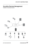
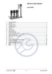
1
GRUNDFOS INSTRUCTIONS
Grundfos CIM/CIU 300
BACnet MS/TP for Grundfos E-pumps
Functional profile and user manual
2
1. Symbol used in this document
Original installation and operating instructions.
CONTENTS
Note
Notes or instructions that make the job easier
and ensure safe operation.
1.
Symbol used in this document
2
2.
2.1
2.2
2.3
2.4
2.5
Introduction
About this functional profile
Assumptions
Definitions and abbreviations
System diagrams
Specifications
2
2
2
2
3
4
3.
3.1
3.2
3.3
3.4
3.5
3.6
3.7
3.8
3.9
BACnet interface
BACnet bus topology
CIM 300 BACnet module
Connecting to the BACnet network
Setting the BACnet transmission speed
Selecting the Device Object Instance Number
Selecting the Device Object Name
Selecting the BACnet MAC address
Termination resistor
Cable length
5
5
6
6
6
6
7
7
7
7
4.
4.1
4.2
LEDs
LED1, BACnet MS/TP communication
LED2, internal communication
8
8
8
5.
5.1
5.2
Supported services
Data sharing services
Device management services
9
9
9
6.
6.1
6.2
6.3
6.4
6.5
6.6
6.7
6.8
Object overview
Device Object
Binary inputs
Binary outputs
Multistate inputs
Multistate outputs
Analog inputs
Analog outputs
Analog values
10
10
11
11
12
12
13
14
14
7.
7.1
7.2
7.3
7.4
7.5
7.6
Detailed descriptions
Control modes
Setpoint
BACnet communication watchdog
Fault monitoring and resetting
Pump control via BACnet
Product simulation
15
15
16
16
16
16
17
2.3 Definitions and abbreviations
8.
8.1
8.2
Commissioning
Step-by-step guide to hardware setup (CIU 300)
Step-by-step guide to hardware setup (CIM 300)
9.
9.1
9.2
2. Introduction
2.1 About this functional profile
This functional profile describes the CIU 300 (BACnet
Communication Interface Unit 300) for the following Grundfos
pumps:
•
GRUNDFOS MAGNA (with add-on GENIbus module)
•
Grundfos UPE Series 2000 (UPE 80-120 and 100-120)
•
Grundfos CRE, CRNE, CRIE, MTRE, CME
(single-phase and three-phase, up to 11 kW)
•
Grundfos CRE, CRNE, CRIE, MTRE, CME
(three-phase, 11-22 kW)
•
Grundfos TPE, TPE Series 2000, NBE, NKE
(single-phase and three-phase, up to 11 kW)
•
Grundfos TPE, TPE Series 2000, NBE, NKE
(three-phase, 11-22 kW)
•
Grundfos CUE frequency converter
(all versions, 0.55 - 250 kW).
The data in this document are subject to change without prior
notice. Grundfos cannot be held responsible for any problems
caused directly or indirectly by using information in this functional
profile.
2.2 Assumptions
This functional profile assumes that the reader is familiar with
commissioning and programming BACnet devices. The reader
should have some basic knowledge of the BACnet protocol and
technical specifications. It is also assumed that an existing
BACnet MS/TP network is present.
CIM
Communication Interface Module,
a Grundfos add-on module
CIU
Communication Interface Unit,
a Grundfos box for CIM modules
17
17
17
CRC
Cyclic Redundancy Check, a data error
detection method
Device
A node on the BACnet MS/TP network
Fault finding
LED status
BACnet faults
18
18
18
GENIbus
Proprietary Grundfos fieldbus standard
based on RS-485
Inter-network
10.
10.1
10.2
BACnet telegrams
BACnet MS/TP telegram overview
Telegram types
19
19
19
A set of two or more BACnet networks
interconnected by routers
LED
Light Emitting Diode
MAC
11.
Grundfos alarm and warning codes
20
Media Access Control, a sublayer of
the data communication protocol
12.
BACnet MAC address
22
MS/TP
13.
Disposal
22
Master-Slave / Token-Passing, a data
protocol used for BACnet RS-485
Router
A device that connects two or more
networks at the network layer
2
Transmission speed
Bits transferred per second
Trunk cable
Main RS-485 cable on a BACnet MS/TP
network
2.4 System diagrams
The system diagrams give an overview of how to connect the
CIM/CIU 300 to the Grundfos pump that is to be connected to
a BACnet network.
CIM 300
The CIM 300 is an add-on communication module to be installed
internally in a Grundfos pump, using a 10-pin connection. In this
setup, the pump will supply power to the CIM 300. See fig. 1.
This installation option is currently available for Grundfos
E-pumps, 11-22 kW.
Pump with built-in CIM 300
BACnet MS/TP
RS-485
Detailed view
TM04 5803 3909
CIM 300
Grundfos Pump
Fig. 1
CIM 300 solution
CIU 300
The CIU 300 solution is a box with a power supply module and
a CIM 300 BACnet module. It can either be mounted on a DIN rail
or on a wall. See fig. 2.
It is used in conjunction with Grundfos E-pumps that do not
support an internal, add-on communication module (CIM 300).
BACnet MS/TP
RS-485
Fig. 2
CIU 300
GENIbus
RS-485
TM04 5804 3909
Pump connected to CIU 300 via GENIbus
CIU 300 solution
3
2.5 Specifications
General data
Description
Comments
GENIbus visual diagnostics
LED2
Red/green status LED.
See section 4.2 LED2, internal communication.
Power supply
24-240 V AC/DC
Located in the CIU 300.
GENIbus connection type
RS-485
GENIbus wire configuration
Three-wire + screen
Communication Interface Unit (CIU 300)
Conductors: A, B and Y.
BACnet
Data protocol
BACnet MS/TP
BACnet connector
Screw-type terminal
BACnet connection type
RS-485
BACnet wire configuration
Two-wire + ground
Maximum cable length
1200 m
Equals 4000 ft.
MAC address
0-127
Set via rotary switches SW6 and SW7.
See section 3.7 Selecting the BACnet MAC address.
Line termination
On or Off
Set via DIP switches SW1 and SW2.
See section 3.8 Termination resistor.
Supported transmission speeds [bits/s]
9600, 19200, 38400, 76800
Set via DIP switches SW4 and SW5.
See section 3.4 Setting the BACnet transmission
speed.
3 pins.
See section 3.2 CIM 300 BACnet module.
Conductors: Plus, Minus and Ground.
See section 3.3 Connecting to the BACnet network.
Data bits
8
Fixed value.
Stop bits
1
Fixed value.
Parity
None
Fixed value.
BACnet visual diagnostics
LED1
Red/green status LED.
See section 4.1 LED1, BACnet MS/TP
communication.
Maximum number of BACnet devices
32
Using repeaters, this number can be increased.
Grundfos BACnet vendor ID
227
BACnet segmentation support
No
Character set support
ANSI X3.4
Base definition for the widely used character code
known as ASCII.
BACnet device profile
B-ASC
BACnet Application-Specific Controller.
BACnet MS/TP master
Yes
The CIM/CIU 300 is a BACnet MS/TP master device.
Manual slave address binding
No
4
3. BACnet interface
3.1 BACnet bus topology
The Grundfos CIM/CIU 300 is connected as a BACnet MS/TP
master directly to the BACnet MS/TP network.
Master
Slave
Slave
Master
LT
Master
BR
Slave
Slave
LT = Line Termination
BR = Bias Resistor
Fig. 3
TM04 1697 0908
LT
Example of BACnet MS/TP network
BACnet MS/TP is a multi-master system, meaning that there can
be more than one master on the network. It uses a token to
control access to the bus network. A master node may initiate the
transmission of a data telegram when it holds the token. Both
master and slave nodes may transmit data telegrams in response
to requests from master nodes, but slaves never hold the token.
Master nodes pass the token between them.
A BACnet MS/TP segment is a single contiguous medium to
which BACnet nodes are attached. Segments can be connected
by use of repeaters or bridges, thus forming networks.
Multiple networks may be interconnected by BACnet routers to
form a BACnet inter-network.
3.1.1 Line termination resistors
Line termination must be connected at each of the two ends of
the segment medium. The CIM/CIU 300 has optional line
termination resistor on board.
3.1.2 Bias resistors
At least one set, and no more than two sets, of network bias
resistors must exist for each segment so that an undriven
communications line will be held in a guaranteed logical one
state. The bias provides a reliable way for stations to detect the
presence or absence of signals on the line. An unbiased line will
take an indeterminate state in the absence of any driving node.
The CIM/CIU 300 has no bias resistors.
5
3.3 Connecting to the BACnet network
3.2 CIM 300 BACnet module
A screened, twisted-pair cable must be used.
BACnet terminal
Recommended colour
Data signal
Plus
Red
Positive
Minus
Green
Negative
Ground
Grey
Ground
The ANSI/ASHRAE BACnet standard states that the cable screen
must only be earthed at one end of the segment to prevent earth
fault currents.
3.4 Setting the BACnet transmission speed
8
1 2 3
Fig. 4
4
5
6
7
TM04 1697 0908
9
TM04 1710 0908
The transmission speed must be set correctly before the CIM 300
is ready to communicate on the BACnet MS/TP network. DIP
switches SW4 and SW5 are used to set the transmission speed.
The default transmission speed is 9600 bits/s, but higher speeds
are recommended for better data throughput. All devices on the
BACnet MS/TP network must communicate at the same
transmission speed.
SW4 SW5
Fig. 5
BACnet transmission speed settings
CIM 300 BACnet module
3.4.1 DIP switch settings
Description
Available transmission speeds in bits/s: 9600, 19200, 38400 and
76800.
1
Plus
BACnet Plus terminal
(RS-485 positive data signal)
2
Minus
BACnet Minus terminal
(RS-485 negative data signal)
Transmission speed
[bits/s]
SW4
SW5
3
Ground
BACnet Ground terminal
9600
OFF
OFF
SW1/SW2
On/off switches for termination
resistor
19200
OFF
ON
38400
ON
OFF
76800
ON
ON
4
5
SW3/SW4/SW5
Switches for selecting the BACnet
transmission speed and the default
or custom Device Object Instance
Number.
6
LED1
Red/green status LED for
BACnet communication
LED2
Red/green status LED for internal
communication between the
CIM 300 and the Grundfos pump
8
SW6
Hexadecimal rotary switch for
setting the BACnet MAC address
(four most significant bits)
9
SW7
Hexadecimal rotary switch for
setting the BACnet MAC address
(four least significant bits)
7
Use DIP switches SW4 and SW5 to select the desired speed.
The default transmission speed is 9600 bit/s, as per the BACnet
MS/TP standard. The transmission speed will be effective
immediately after setting the values of the DIP switch.
3.5 Selecting the Device Object Instance Number
The Device Object Identifier value consists of two components:
•
a 10-bit Object Type (bits 22 - 31)
•
a 22-bit Instance Number (bits 0 - 21).
31
22
21
...
Object type
Instance Number
10 bits
22 bits
Fig. 6
0
Bit numbers
The Object Type is fixed and determines that it is a Device
Object. The Instance Number is a numeric code that is used to
identify the device. It must be unique inter-network-wide, i.e. on
all interconnected networks.
The CIM 300 offers two different approaches to setting the
BACnet Device Object Instance Number: default and custom,
both described in the following subsections.
6
TM04 5977 4509
Pos. Designation
3.5.1 Default Instance Number
By default, the CIM 300 uses a pre-defined Device Object
Instance Number, which is 227XXX where XXX is the BACnet
MAC address. This gives an Instance Number range of 227000 to
227127. See section 3.7 Selecting the BACnet MAC address for
more information on MAC addresses.
For a complete overview of BACnet addresses, see section
12. BACnet MAC address.
Note
The BACnet MAC address must be set decimally
from 0 to 127 and must be unique on the BACnet
MS/TP segment.
Example:
3.8 Termination resistor
The BACnet MAC address is set to 20 via the hexadecimal rotary
switches, so the Device Object Instance Number is 227020.
A termination resistor for line termination is fitted on the CIM 300
and has a value of 120 Ω. It should be cut in if the CIM 300 is set
as the last station on the network.
TM04 1709 0908
To use the complete Instance Number range, set the new
Instance Number with the BACnet object Custom Device Object
Instance Number (AV, 0), and set SW3 to ON. This will
immediately set the new Device Object Instance Number.
See fig. 7 for DIP switch location.
SW3
Fig. 7
Device Object Instance Number
Device Object Instance Number
SW3
Default (227000 + BACnet MAC address)
OFF
Custom, set with object (AV, 0)
ON
The CIM 300 has two DIP switches (SW1 and SW2) for cutting
the termination resistor in and out. Figure 8 shows the DIP
switches in cut-out state.
TM04 1701 0908
3.5.2 Custom Instance Number
SW1 SW2
Fig. 9
Cutting the termination resistor in and out
Status
SW1
SW2
Cut-in
ON
ON
Cut-out
OFF
OFF
ON
OFF
OFF
ON
The default Present_Value of the Custom Device Object Instance
Number is 231.
Default setting: Termination resistor cut-out.
Example:
3.9 Cable length
The Present_Value of Custom Device Object Instance Number
(AV, 0) is 231, so the Device Object Instance Number is 231.
The maximum recommended cable length within a BACnet
MS/TP segment is 1200 metres (4000 ft) with 0.82 mm2
(AWG 18) cable.
Note
The Present_Value of Custom Device Object
Instance Number cannot be 4194303, as this is
a reserved value.
The connection between the BACnet modules must be made by
use of a screened, twisted-pair cable with a characteristic
impedance between 100 and 130 Ω.
3.6 Selecting the Device Object Name
The property Device_Name is a character string that must be
unique inter-network-wide. By default, the name will be
constructed as "Grundfos - XXXXXX" where XXXXXX is the
current Device Object Instance Number as described in section
3.5 Selecting the Device Object Instance Number.
Example:
The Device Object Instance Number is 227001, so the Device
Object Name is "Grundfos - 227001".
If a new name is selected, it will be stored in the device and
replace the default naming scheme.
3.7 Selecting the BACnet MAC address
To set the BACnet MAC address, use the two hexadecimal rotary
switches (SW6 and SW7).
SW6
Fig. 8
SW7
TM04 1706 0908
The value must be within the range of 0 to 127. An illegal value
will result in a MAC address of 0.
Setting the BACnet MAC address
7
4. LEDs
The CIM 300 BACnet module has two LEDs.
•
Red/green status LED (LED1) for BACnet MS/TP
communication
•
Red/green status LED (LED2) for internal communication
between the CIM 300 and the Grundfos pump.
4.1 LED1, BACnet MS/TP communication
Status
Description
Off
No communication.
Flashing green
Communication active.
Flashing red
Fault in the BACnet communication.
Permanently red
Fault in the CIM 300 BACnet
configuration.
4.2 LED2, internal communication
Status
Description
Off
The CIM 300 has been switched off or
is starting up
Flashing red
No internal communication between the
CIM 300 and the pump.
Permanently red
The CIM 300 does not support the
specific pump version.
Permanently green
Internal communication between the
CIM 300 and the pump is OK.
Note
8
During start-up, there may be a delay of up to
5 seconds before the LED status is updated.
5. Supported services
BACnet Interoperability Building Blocks (BIBBs) are collections of one or more BACnet services. These are described in terms of an "A"
and a "B" device. Both devices are nodes on a BACnet inter-network. In most cases, the "A" device will act as the user of data (client),
and the "B" device will be the provider of this data (server).
The CIM/CIU 300 is a BACnet Application-Specific Controller (B-ASC) with a few additional services.
5.1 Data sharing services
Name
BACnet BIBB code
Notes
ReadProperty
DS-RP-B
The CIM/CIU 300 can be a provider of data.
X
ReadPropertyMultiple
DS-RPM-B
The CIM/CIU 300 can be a provider of data and
return multiple values at one time.
X
WriteProperty
DS-WP-B
The CIM/CIU 300 allows a value to be changed over the
network.
X
WritePropertyMultiple
DS-WPM-B
The CIM/CIU 300 allows multiple values to be changed
over the network.
X
DS-COV-B
The CIM/CIU 300 can be a provider of "Change Of Value"
data. It supports up to 10 simultaneous COV
subscriptions. Subscription lifetime can be limited or
unlimited.
SubscribeCOV
ConfirmedCOVNotification
UnconfirmedCOVNotification
Initiate
Execute
X
X
X
5.2 Device management services
Name
BACnet BIBB code
Notes
DM-DDB-A
The CIM/CIU 300 can seek information about device
attributes of other devices and interpret device
announcements.
DM-DDB-B
The CIM/CIU 300 can provide information about its device
attributes and responds to requests to identify itself.
X
DM-DOB-B
The CIM/CIU 300 can provide address information about
its objects upon request.
X
DM-DCC-B
The CIM/CIU 300 can respond to communication control
requests. It supports both limited and unlimited duration.
Password (where required) is Grundfos.
Who-Is
I-Am
Who-Is
I-Am
Who-Has
I-Have
DeviceCommunicationControl
Initiate
Execute
X
X
X
X
X
9
6. Object overview
6.1 Device Object
The following properties are supported in the Device Object (available for all pump types).
Property identifier
Data type
Note
Access
Object_Identifier
BACnetObjectIdentifier
See section 3.5 Selecting the Device Object
Instance Number.
R
Object_Name
CharacterString
See section 3.6 Selecting the Device Object Name
for details on Object Name.
W
Object_Type
BACnetObjectType
DEVICE.
R
System_Status
BACnetDeviceStatus
OPERATIONAL.
R
Vendor_Name
CharacterString
Grundfos.
R
Vendor_Identifier
Unsigned16
227.
R
CharacterString
Will show the Grundfos pump model to which the
CIM/CIU 300 is connected.
R
Model_Name
Firmware_Revision
CharacterString
Revision of the firmware in the CIM/CIU 300.
R
Application_Software_Version
CharacterString
Software build date, DD-MM-YYYY.
R
Location
CharacterString
The user can enter a location here
(maximum 200 characters).
W
Description
CharacterString
The user can enter a description here
(maximum 200 characters).
W
Protocol_Version
Unsigned
Actual version of the BACnet protocol.
R
Protocol_Revision
Unsigned
Actual revision of the BACnet protocol.
R
Protocol_Services_Supported
BACnetServicesSupported
Indicates which standardised protocol services are
supported.
R
Indicates which standardised protocol object types
are supported.
R
Protocol_Object_Types_Supported BACnetObjectTypesSupported
Object_List
BACnetARRAY[N]of
BACnetObjectIdentifier
An array of objects available.
R
Max_APDU_Length_Accepted
Unsigned
The maximum number of bytes that may be
contained in a single APDU. Fixed to 480.
R
Segmentation_Supported
BACnetSegmentation
Indicates if segmentation of messages is possible.
Will always read NO_SEGMENTATION to indicate
that segmentation is not possible.
R
APDU_Timeout
Unsigned
Indicates the amount of time in ms before timeout.
R
Unsigned
Maximum number of times an APDU is to be
retransmitted.
R
Max_Master
Unsigned
Specifies the highest possible address for master
nodes and must be between 1 and 127.
The default value is 127, but this value can be
lowered by the user to reduce transmission
overhead.
W
Max_Info_Frames
Unsigned
Specifies the maximum number of information
frames that are sent before the token is passed on.
Fixed to 1.
R
Number_Of_APDU_Retries
Device_Address_Binding
List of BACnetAddressBindings
Holds address bindings to other devices, if any.
R
Database_Revision
Unsigned
Logical revision number for the device database.
R
10
6.2 Binary inputs
Binary objects that provide information from the Grundfos pump.
MAGNA
+
UPE
E-pumps
0.25 - 7.5 kW
CUE +
E-pumps
11 - 22 kW
X
X
X
X
X
X
X
X
0 = Not running at minimum speed
1 = Running at minimum speed.
X
X
X
R
0 = Not running at maximum speed
1 = Running at maximum speed.
X
X
X
Digital input 1 status
R
0 = Not active
1 = Active.
X
X
BI, 12
Digital input 2 status
R
0 = Not active
1 = Active.
X
X
BI, 13
Digital input 3 status
R
0 = Not active
1 = Active.
X
X
BI, 14
Digital output 1 status
R
0 = Not active
1 = Active.
X
X
BI, 15
Digital output 2 status
R
0 = Not active
1 = Active.
X
X
BI, 28
Fault simulation status
R
Fault simulation status.
0 = Fault simulation not active
1 = Fault simulation active.
X
X
X
MAGNA
+
UPE
E-pumps
0.25 - 7.5 kW
CUE +
E-pumps
11 - 22 kW
X
X
X
X
X
ID
Object Name
R/W
Notes
BI, 0
Control source status
R
Status of the actual control source.
0 = Local control
1 = Bus control.
BI, 1
Actual direction
R
Rotational direction of the pump impeller.
0 = Forward
1 = Reverse.
BI, 2
Rotation status
R
Rotation status.
0 = No rotation
1 = Rotation (pump running).
BI, 3
At minimum speed
R
BI, 4
At maximum speed
BI, 11
6.3 Binary outputs
Binary objects for control of the Grundfos pump.
ID
Object Name
R/W
Notes
BO, 0
Set control source
W
Sets the control source.
Set to 1 to enable pump control via BACnet.
0 = Local control (default)
1 = Bus control.
BO, 1
Relay 1 control
W
Controls relay 1 if bus control is enabled and
relay 1 is set to be controlled via bus.
0 = Closed (default)
1 = Open.
BO, 2
Relay 2 control
W
Controls relay 2 if bus control is enabled and
relay 2 is set to be controlled via bus.
0 = Closed (default)
1 = Open.
BO, 3
Set direction
W
Sets rotational direction of the pump
impeller if bus control is enabled.
0 = Forward (default)
1 = Reverse.
BO, 4
Reset fault
W
Resets alarm if bus control is enabled.
(Triggered on rising edge).
0 = No resetting (default)
1 = Resetting.
W
Enables simulated fault if bus control is
enabled.
0 = Disabled (default)
1 = Enabled.
BO, 5
Fault simulation
X
X
X
X
X
X
X
X
X
11
6.4 Multistate inputs
Objects that contain an enumeration value from the pump.
ID
MI, 0
MI, 1
MI, 2
MI, 3
Object Name
Actual control mode
Actual operating mode
MAGNA
+
UPE
E-pumps
0.25 - 7.5 kW
CUE +
E-pumps
11 - 22 kW
R
Reads the current control mode.
1 = Constant speed
2 = Constant pressure
3 = Proportional pressure
4 = Automatic / AUTOADAPT
5 = Constant flow
6 = Constant temperature
7 = Constant level
8 = Constant percentage.
See section 7.1 Control modes for details
on the control modes.
X
X
X
R
Reads the current operating mode.
1 = Start (normal)
2 = Stop
3 = Minimum
4 = Maximum.
X
X
X
R/W
Notes
Next bearing-service type R
Type of next bearing service.
1 = Service type unknown
2 = Lubricate bearings
3 = Change bearings.
CIM status
Reads the status of the CIM module,
useful for fault finding.
1 = OK
2 = EEPROM fault
3 = Memory fault.
R
X
X
X
X
MAGNA
+
UPE
E-pumps
0.25 - 7.5 kW
CUE +
E-pumps
11 - 22 kW
6.5 Multistate outputs
Objects that set an enumeration value in the pump.
ID
MO, 0
MO, 1
MO, 2
12
Object Name
Set control mode
Set operating mode
Product simulation
R/W
Notes
W
Sets the control mode if bus control is
enabled.
1 = Constant speed
2 = Constant pressure
3 = Proportional pressure
4 = Automatic / AUTOADAPT
5 = Constant flow
6 = Constant temperature
7 = Constant level
8 = Constant percentage.
See section 7.1 Control modes for details
on the control modes.
X
X
X
W
Sets the operating mode if bus control is
enabled.
1 = Start (normal)
2 = Stop
3 = Minimum
4 = Maximum.
X
X
X
W
Enables product simulation
(for commissioning and testing purposes,
can only be enabled when no physical pump
is present).
1 = Disabled (default)
2 = MAGNA
3 = E-pumps 0.25 - 7.5 kW
4 = E-pumps 11 - 22 kW / CUE.
See section 7.6 Product simulation for
details.
X
X
X
6.6 Analog inputs
Objects with measured values and status information from the pump.
E-pumps
0.25 - 7.5
kW
CUE +
E-pumps
11 - 22
kW
X
X
X
X
X
Object Name
R/W Notes
AI, 0
Fault code
R
Grundfos fault code.
See section 11. Grundfos alarm and warning codes.
AI, 1
Warning code
R
Grundfos warning code.
See section 11. Grundfos alarm and warning codes.
AI, 2
Time to bearing service
R
Time to bearing service in months.
A value of 24 means "24 or more".
month
AI, 3
Capacity
R
Actual capacity value (process feedback).
%
X
X
AI, 4
Head
R
Actual system head/pressure.
bar
S
S
S
AI, 5
Flow
R
Actual system flow.
m3/h
S*
S*
S*
AI, 6
Relative performance
R
Performance relative to maximum performance.
%
X
X
X
AI, 7
Speed
R
Motor speed.
rpm
X
X
X
AI, 8
Frequency
R
Actual control signal applied to motor.
Hz
X
X
X
AI, 9
Actual setpoint
R
Actual setpoint.
%
X
X
X
AI, 10 Motor current
R
Actual motor current.
A
X
X
AI, 11 DC link voltage
R
Frequency converter DC Link voltage.
V
X
X
AI, 12 Motor voltage
R
Motor voltage.
V
AI, 13 Power
R
Total power consumption of the pump.
W
AI, 14 Remote flow
R
Measured flow at external sensor.
m3/h
S
AI, 15 Inlet pressure
R
System inlet pressure.
bar
S
AI, 16 Remote pressure
R
Measured pressure at external sensor.
bar
AI, 17 Level
R
Tank level.
m
S
S
R
Temperature in frequency converter.
C°
X
X
AI, 19 Motor temperature
R
Motor winding temperature.
C°
AI, 20 Remote temperature
R
Temperature at external sensor.
C°
AI, 21 Electronic temperature
R
Pump electronics temperature.
C°
AI, 22 Fluid temperature
R
Pumped-liquid temperature.
C°
S
AI, 23 Bearing temperature DE
R
Bearing temperature, drive end.
C°
S
AI, 24 Bearing temperature NDE R
Bearing temperature, non-drive end.
C°
AI, 25 Auxiliary sensor input
R
Auxiliary sensor input.
%
AI, 26 Specific energy
R
Specific energy consumption.
kWh/m3
AI, 27 Runtime
R
Total operating time of the pump.
h
X
X
AI, 28 Total ontime
R
Total power-on time of the pump.
h
X
X
X
AI, 29 Torque
R
Motor torque.
Nm
3ph
X
AI, 30 Energy consumption
R
Total energy consumption of the pump.
kWh
AI, 31 Number of starts
R
Number of times the pump has started.
-
AI, 32 Volume
R
Total pumped volume.
m3
AI, 18
X
Power electronic
temperature
Unit
MAGNA
+
UPE
ID
X
X
X
X
X
X
X
X
S
X
S
S
S
S
S
S
CUE
X
X
X
X
X
X
CUE
= Always available.
S
= Sensor required.
S*
= On TPE Series 2000 and MAGNA/UPE, the flow is
estimated and is only to be used for monitoring, not for
control purposes.
On all other pump types, a flow sensor is required.
CUE = Only available on CUE (with sensor).
3ph
= Only available on three-phase E-pumps.
13
6.7 Analog outputs
Object for setting a new setpoint in the pump.
ID
Object Name
AO, 0 Set setpoint
R/W Notes
W
Sets the pump setpoint if bus control is enabled.
A value of 0 does not imply a stop.
See section 7.2 Setpoint.
Unit
%
MAGNA
+
UPE
E-pumps
0.25 - 7.5
kW
CUE +
E-pumps
11 - 22
kW
X
X
X
MAGNA
+
UPE
E-pumps
0.25 - 7.5
kW
CUE +
E-pumps
11 - 22
kW
6.8 Analog values
Objects for configuration of the CIM/CIU 300 and/or the pump.
ID
Object Name
R/W Notes
Unit
Custom Device Object
Instance Number
Value for Custom Device Object Instance Number.
Used in conjunction with DIP switch SW3.
See section 3.5 Selecting the Device Object
R/W
Instance Number.
Present_Value range: 0-0x3FFFFE.
Default Present_Value: 0xE7.
-
X
X
X
AV, 1
BACnet watchdog
Time in seconds before BACnet communication
watchdog times out, and sets the pump to local
control mode.
s
R/W
See section 7.3 BACnet communication watchdog.
0 = Disabled (default)
Set to a value between 5 and 3600 to enable.
X
X
X
AV, 2
Simulation fault code
Fault code to simulate.
R/W See section 11. Grundfos alarm and warning codes. Can be cleared by writing a value of 0.
X
X
X
AV, 3
Simulation warning code
Warning code to simulate.
R/W See section 11. Grundfos alarm and warning codes. Can be cleared by writing a value of 0.
X
X
AV, 0
14
7. Detailed descriptions
7.1 Control modes
Control modes
Description
Illustration
H
No sensor is required.
H
The controller inside the pump will adapt the pump speed so
that the pressure is constant, regardless of the flow.
A pressure sensor is required.
Q
Constant
Constant
Constant
Constant
flow
level
temperature
percentage
Closed loop
Constant flow, constant level, constant temperature or constant
percentage can be obtained by replacing the main pressure
sensor with another sensor, e.g. a flow sensor is needed for
flow control, a level sensor is needed for level control and a
temperature sensor is needed for temperature control.
TM04 2290 2208
Constant pressure
Closed loop
The setpoint of the pump will be interpreted as setpoint for the
pressure.
Q
TM04 2289 2208
The setpoint value is a percentage of the maximum speed of
the pump.
H
Constant flow is illustrated to the right.
Q
TM04 2288 2208
Constant speed
Open loop
The setpoint of the pump will be interpreted as setpoint for the
pump speed in %.
This control mode is only available on GRUNDFOS MAGNA
and TPE Series 2000 pumps.
Q
Automatic / AUTOADAPT
Automatic
For this control mode, the optimum setpoint is automatically
estimated and used. This also means that any setpoint value is
ignored.
H
Only available on GRUNDFOS MAGNA and some three-phase
motors of 0.55 - 7.5 kW.
A pressure sensor is required.
Q
TM04 2287 2208
Proportional pressure
TM04 2291 2208
H
Closed loop
The setpoint of the pump will be interpreted as basic setpoint
for the proportional-pressure mode (the black dot in the
illustration).
H = Pressure (Head)
Q = Flow
Important notes to control modes
Only valid control modes will be accepted.
Example: If the pump is a TPE Series 2000, and the control
mode is changed to Constant temperature, the pump will not
change its control mode because it is not possible for a
TPE Series 2000 to run in this mode. The mode will then be
the last valid control mode.
15
7.2 Setpoint
7.3 BACnet communication watchdog
This object accepts values ranging from 0 to 100 (0 % to 100 %).
This is illustrated in fig. 10.
A BACnet communication watchdog is implemented in the
CIM/CIU 300. If no BACnet communication is detected for the
time period defined by the BACnet watchdog object (AV, 1) and
the pump is set to Bus control mode (BO, 0), the pump is
automatically switched to local control mode, and its local
settings will be used.
The setpoint is a percentage of the maximum
setpoint or sensor maximum (max. = 100 %).
Note
The setpoint value can represent speed, pressure, flow, etc.,
depending on the selected control mode.
This functionality can be used to define the pump behaviour in
case of a BACnet communication breakdown. Before enabling
the watchdog, the local pump settings should be made with either
a Grundfos PC Tool or the Grundfos R100 remote control. This
ensures that the pump behaves as expected if the BACnet
communication breaks down.
A setpoint of 0 does not imply a stop.
Effective setpoint
Sensor
maximum
Minimum
setpoint
0%
Setpoint [%]
100 %
TM04 2373 2508
When BACnet communication is re-established after a watchdog
timeout, the user must manually set the pump back to Bus control
mode (BO, 0).
7.4 Fault monitoring and resetting
This example shows how to monitor faults or warnings in the
Grundfos pump and how to manually reset a fault.
The Fault code object (AV, 0) and the Warning code object (AV, 1)
can both hold a Grundfos-specific fault code. See section
11. Grundfos alarm and warning codes for code interpretation.
Fig. 10 Setpoint
7.2.1 Setpoint examples
Closed loop
If the control mode is set to Constant pressure (closed loop) and
the pressure sensor is in the range of 0 to 10 bar, a setpoint of
80 % will result in an effective setpoint of 8 bar.
If the sensor range was 0 to 16 bar, a 50 % setpoint would be
8 bar, a 25 % setpoint would be 4 bar, and so on.
Warnings are notifications only and will not stop the pump,
whereas faults will stop the pump. Most pumps can be configured
to either automatically reset the fault when the fault condition
disappears or to require manual resetting.
If a fault is to be manually reset, use the Reset fault object
(BO, 4). When the Present_Value of this object is set to 1,
a Reset fault command is sent to the device.
7.5 Pump control via BACnet
10 bar
This example shows how to set a GRUNDFOS MAGNA to 50 %
setpoint, in proportional-pressure mode.
0%
80 %
100 %
TM04 2371 2508
8 bar
Fig. 11 Constant pressure
Open loop
If the control mode is set to Constant speed (open loop), the
setpoint is interpreted as setpoint for the pump performance.
Maximum
pump
performance
0%
Fig. 12 Constant speed
50 %
100 %
TM04 2372 2508
50 % system
performance
16
When the Present_Value of the AV, 1 object is set to 0, the
watchdog is disabled (default). To enable the watchdog, set the
Present_Value to [5-3600] seconds.
•
Before enabling pump control via BACnet, values for setpoint,
control mode and operating mode should be set.
•
Set operating mode with Multistate output 1. In this example,
the value for operating mode should be 1 (Start).
•
Set control mode with Multistate output 0. A value of 3
corresponds to Proportional pressure.
•
Set the setpoint to a value of 50 % in Analog output 0.
See section 7.2 Setpoint for details on setpoint.
•
To enable bus control, set Binary output 0 to a value of 1.
Now the GRUNDFOS MAGNA pump should be running at 50 %
in proportional-pressure mode, with bus control enabled.
7.6 Product simulation
Product profile simulation (pump simulation) can be useful for
testing and pre-commissioning purposes. It is possible to
simulate a pump profile when using a CIU 300 that is not
connected to a pump. The CIU 300 will behave as if a pump was
connected on the GENIbus, even if that is not the case. The
objects supported by the simulated product will be available,
although the data will only be dummy values that do not simulate
real pump behaviour.
Product simulation is enabled by setting the Multistate output
object "Product simulation" (MO, 2):
Product to simulate
Value
Disabled (no simulation)
1
MAGNA / UPE
2
E-pumps 0.25 - 7.5 kW
3
E-pumps 11 - 22 kW /CUE
4
Note
Product simulation will always be disabled on
power-up.
Note
If a physical pump is detected on GENIbus during
power-up, it will not be possible to enable
product simulation.
8. Commissioning
8.1 Step-by-step guide to hardware setup (CIU 300)
Step
1
Action
Complete the pump configuration, e.g. sensor configuration.
2
Select the BACnet MAC address (0-127) on the CIM 300. See section 3.7 Selecting the BACnet MAC address.
3
Select the transmission speed of the CIM 300. See section 3.4 Setting the BACnet transmission speed.
4
Select Device Object Instance Number. See section 3.5 Selecting the Device Object Instance Number.
5
If necessary, set line termination. See section 3.8 Termination resistor.
6
Connect the GENIbus cable from the CIU 300 to the pump.
7
Connect the necessary cables from the CIU 300 to the BACnet network. See section 3.3 Connecting to the BACnet network.
8
Connect the power supply cable to the CIU 300, and switch it on.
9
Confirm that the GENIbus LED is constantly green and that the BACnet LED is either off or flashing green
(indicating communication). See section 4. LEDs.
The CIU 300 is now configured and ready.
8.2 Step-by-step guide to hardware setup (CIM 300)
Step
1
Action
Complete the pump configuration, e.g. sensor configuration.
2
Select the BACnet MAC address (0-127) on the CIM 300. See section 3.7 Selecting the BACnet MAC address.
3
Select the transmission speed of the CIM 300. See section 3.4 Setting the BACnet transmission speed.
4
Select Device Object Instance Number. See section 3.5 Selecting the Device Object Instance Number.
5
If necessary, set line termination. See section 3.8 Termination resistor.
6
Connect the necessary cables from the CIM 300 to the BACnet network. See section 3.3 Connecting to the BACnet network.
7
Confirm that the GENIbus LED is constantly green and that the BACnet LED is either off or flashing green
(indicating communication). See section 4. LEDs.
The CIM 300 is now configured and ready.
17
9. Fault finding
9.1 LED status
Faults in a CIM/CIU 300 can be detected by observing the status of the two communication LEDs. See the table below.
Fault (LED status)
Possible cause
Remedy
1. Both LEDs (LED1 and
LED2) remain off when the
power supply is connected,
and 5 seconds have
passed.
a) The CIM 300 is defective.
Replace the CIM 300.
2. The LED for internal
communication (LED2)
is flashing red.
a) No internal communication between the
CIM/CIU 300 and the Grundfos pump.
• Check the cable connection between the pump
and the CIU 300.
• Check that the individual conductors have been
fitted correctly.
• Check the power supply to the pump.
3. The LED for internal
communication (LED2)
is constantly red.
a) The CIU 300 does not support the
connected pump.
Contact the nearest Grundfos company.
4. The BACnet LED (LED1)
is constantly red.
a) Fault in the CIM 300 BACnet configuration. • Ensure that the BACnet MAC address has a valid
setting. See section 3.7 Selecting the BACnet
MAC address.
• Ensure that the Device Object Instance Number is
within the allowed range.
See section 3.5 Selecting the Device Object
Instance Number.
5. The BACnet LED (LED1)
is flashing red.
a) Fault in the BACnet communication
(cyclic redundancy check).
• Check the transmission speed
(switches SW4 and SW5).
See section 3.4 Setting the BACnet transmission
speed.
• Check the cable connection between the CIM 300
and the BACnet network.
• Check the termination resistor settings
(switches SW1 and SW2).
See section 3.8 Termination resistor.
Fault
Possible cause
Remedy
1. The CIM/CIU 300 does not
communicate on the
BACnet MS/TP network.
a) Configuration or wiring fault.
Ensure that the cable between the BACnet MS/TP
devices is connected correctly.
See section 3.3 Connecting to the BACnet network
for wiring recommendations.
9.2 BACnet faults
Ensure that the BACnet MAC address and Device
Object Instance Number are configured correctly and
are unique on the network.
See section 3.7 Selecting the BACnet MAC address
and 3.5 Selecting the Device Object Instance
Number for address selections.
Ensure that the transmission speed is configured
correctly.
See section 3.4 Setting the BACnet transmission
speed.
Ensure that each end of the BACnet MS/TP
trunk cable is terminated, if necessary.
See section 3.8 Termination resistor for line
termination of the Grundfos CIM/CIU 300.
Ensure that the bus topology for
a BACnet MS/TP network is correct.
b) The CIM/CIU 300 is instructed to not
communicate on the BACnet network via
the DeviceCommunicationControl service.
Use the Device Communication Control service to
enable communication from the device.
2. The pump does not react to
control commands from the
bus.
a) The pump is running in local mode.
Set the pump to bus control by setting the
Present_Value of BO, 0 to 1.
3. There are only a few
BACnet objects available,
and the GENIbus LED
flashes red.
a) There is no communication between the
CIM 300 and the pump.
Ensure that the GENIbus cable between the CIM 300
and the pump is connected correctly.
Ensure that the pump is switched on and able to
communicate on GENIbus.
18
10. BACnet telegrams
10.1 BACnet MS/TP telegram overview
All BACnet MS/TP telegrams have the following format:
Preamble
Telegram
type
Destination
Source
Length
Header CRC
Data
Data CRC
(Pad)
2 bytes:
0x55 0xFF
1 byte
1 byte
1 byte
2 bytes,
MSB first
1 byte
Variable,
[0-501]
bytes
2 bytes,
LSB first
At most
1 byte
0xFF
For BACnet MS/TP, the destination address and source address are MAC addresses. See section 3.7 Selecting the BACnet MAC
address. A destination address of 255 (0xFF) denotes broadcast.
The Length field specifies the length in bytes of the data field which must be between 0 and 501 bytes long.
10.2 Telegram types
The available telegram types are listed below.
Type
Name
00
Token
Description
Used to pass network mastership to the destination device.
01
Poll for master
Discovers the presence of other master devices on the network.
02
Reply to poll for master
Used by a master to indicate a wish to enter the token ring.
03
Test request
Used to initiate a loopback test.
04
Test response
A reply to a test request telegram.
05
BACnet data, expecting reply
Used for data transmission where a reply is expected.
06
BACnet data, not expecting reply
Used for data transmission where no reply is expected.
07
Reply postponed
Used by master devices to defer sending a BACnet data reply.
19
11. Grundfos alarm and warning codes
This is a general Grundfos alarm and warning code list.
Code Description
Code Description
Code Description
1
Leakage current
35
Gas in pump head, deaerating
problem
76
Internal communication fault
2
Missing phase
36
Discharge valve leakage
77
Communication fault, twin-head
pump
3
External fault signal
37
Suction valve leakage
78
Fault, speed plug
4
Too many restarts
38
Vent valve defective
79
Functional fault, add-on module
5
Regenerative braking
40
Undervoltage
80
Hardware fault, type 2
6
Mains fault
41
Undervoltage transient
81
Verification error, data area (RAM)
7
Too many hardware shutdowns
42
Cut-in fault (dV/dt)
82
Verification error, code area (ROM,
FLASH)
8
PWM switching frequency reduced
45
Voltage asymmetry
83
Verification error, FE parameter
area (EEPROM)
9
Phase sequence reversal
48
Overload
84
Memory access error
10
Communication fault, pump
49
Overcurrent (i_line, i_dc, i_mo)
85
Verification error, BE parameter
area (EEPROM)
11
Water-in-oil fault (motor oil)
50
Motor protection function,
general shutdown (mpf)
88
Sensor fault
12
Time for service
(general service information)
51
Blocked motor/pump
89
Signal fault, (feedback) sensor 1
13
Moisture alarm, analog
52
Motor slip high
90
Signal fault, speed sensor
14
Electronic DC-link protection
activated (ERP)
53
Kipped motor
91
Signal fault, temperature 1 sensor
15
Communication fault, main system
(SCADA)
54
Motor protection function,
3 sec. limit
92
Calibration fault, (feedback) sensor
16
Other
55
Motor current protection activated
(MCP)
93
Signal fault, sensor 2
17
Performance requirement cannot
be met
56
Underload
94
Limit exceeded, sensor 1
Limit exceeded, sensor 2
18
Commanded alarm standby (trip)
57
Dry running
95
19
Diaphragm break (dosing pump)
58
Low flow
96
Setpoint signal outside range
20
Insulation resistance low
59
No flow
97
Signal fault, setpoint input
21
Too many starts per hour
64
Overtemperature
98
Signal fault, input for setpoint
influence
22
Moisture switch alarm, digital
65
Motor temperature 1
(t_m or t_mo or t_mo1)
99
Signal fault, input for analog
setpoint
23
Smart trim gap alarm
66
Temperature, control electronics
(t_e)
104
Software shutdown
24
Vibration
67
Temperature too high, internal
frequency converter module (t_m)
105
Electronic rectifier protection
activated (ERP)
25
Setup conflict
68
External temperature/
water temperature (t_w)
106
Electronic inverter protection
activated (EIP)
26
Load continues even if the motor
has been switched off
69
Thermal relay 1 in motor
(e.g. Klixon)
110
Skew load, electrical asymmetry
27
External motor protector activated
(e.g. MP 204)
70
Thermal relay 2 in motor
(e.g. thermistor)
111
Current asymmetry
28
Battery low
71
Motor temperature 2
(Pt100, t_mo2)
112
Cos ϕ too high
29
Turbine operation (impellers forced
backwards)
72
Hardware fault, type 1
113
Cos ϕ too low
30
Change bearings
(specific service information)
73
Hardware shutdown (HSD)
120
Auxiliary winding fault
(single-phase motors)
31
Change varistor(s)
(specific service information)
74
Internal supply voltage too high
121
Auxiliary winding current too high
(single-phase motors)
32
Overvoltage
75
Internal supply voltage too low
122
Auxiliary winding current too low
(single-phase motors)
20
Code Description
Code Description
Code Description
123
Start capacitor, low
(single-phase motors)
183
Signal fault, extra temperature
sensor
216
Pilot pump alarm
124
Run capacitor, low
(single phase motors)
184
Signal fault, general-purpose
sensor
217
Alarm, general-purpose sensor
high
144
Motor temperature 3
(Pt100, t_mo3)
185
Unknown sensor type
218
Alarm, general-purpose sensor low
145
Bearing temperature high (Pt100),
in general or top bearing
186
Signal fault, power meter sensor
219
Pressure relief not adequate
146
Bearing temperature high (Pt100),
middle bearing
187
Signal fault, energy meter
220
Fault, motor contactor feedback
147
Bearing temperature high (Pt100),
bottom bearing
188
Signal fault, user-defined sensor
221
Fault, mixer contactor feedback
148
Motor bearing temperature high
(Pt100) in drive end (DE)
190
Sensor limit 1 exceeded
(e.g. alarm level in WW
application)
222
Time for service, mixer
149
Motor bearing temperature high
(Pt100) in non-drive end (NDE)
191
Sensor limit 2 exceeded
(e.g. high level in WW application)
223
Maximum number of mixer starts
per hour exceeded
152
Communication fault, add-on
module
192
Sensor limit 3 exceeded
(e.g. overflow level in WW
application)
224
Pump fault (due to auxiliary
component or general fault)
153
Fault, analog output
193
Sensor limit 4 exceeded
225
Communication fault, pump
module
154
Communication fault, display
194
Sensor limit 5 exceeded
226
Communication fault, I/O module
155
Inrush fault
195
Sensor limit 6 exceeded
227
Combi event
156
Communication fault, internal
frequency converter module
196
Operation with reduced efficiency
228
Not used
157
Real-time clock out of order
197
Operation with reduced pressure
229
Not used
158
Hardware circuit measurement
fault
198
Operation with increased power
consumption
230
Network alarm
159
CIM fault (Communication
Interface Module)
199
Process out of range (monitoring/
estimation/calculation/control)
231
Ethernet: No IP address from
DHCP server
160
GSM modem, SIM card fault
200
Application alarm
232
Ethernet: Auto-disabled due to
misuse
168
Signal fault, pressure sensor
201
External sensor input high
233
Ethernet: IP address conflict
169
Signal fault, flow sensor
202
External sensor input low
236
Pump 1 fault
170
Signal fault, water-in-oil (WIO)
sensor
203
Alarm on all pumps
237
Pump 2 fault
171
Signal fault, moisture sensor
204
Inconsistency between sensors
238
Pump 3 fault
172
Signal fault, atmospheric pressure
sensor
205
Level float switch sequence
inconsistency
239
Pump 4 fault
173
Signal fault, rotor position sensor
(Hall sensor)
206
Water shortage, level 1
240
Lubricate bearings
(specific service information)
174
Signal fault, rotor origo sensor
207
Water leakage
241
Motor phase failure
175
Signal fault, temperature 2 sensor
(t_mo2)
208
Cavitation
242
Automatic motor model recognition
failed
176
Signal fault, temperature 3 sensor
(t_mo3)
209
Non-return valve fault
243
Motor relay has been forced
(manually operated/commanded)
177
Signal fault, Smart trim gap sensor
210
Overpressure
244
Fault, On/Off/Auto switch
178
Signal fault, vibration sensor
211
Underpressure
245
Pump continuous runtime too long
179
Signal fault, bearing temperature
sensor (Pt100), general or
top bearing
212
Diaphragm tank precharge
pressure out of range
246
User-defined relay has been
forced (manually operated/
commanded)
180
Signal fault, bearing temperature
sensor (Pt100), middle bearing
213
VFD not ready
247
Power-on notice (device/system
has been switched off)
181
Signal fault, PTC sensor
(short-circuited)
214
Water shortage, level 2
248
Fault, battery/UPS
182
Signal fault, bearing temperature
sensor (Pt100), bottom bearing
215
Soft pressure build-up timeout
21
12. BACnet MAC address
BACnet
address
SW6
SW7
BACnet
address
SW6
SW7
BACnet
address
SW6
SW7
0
0
0
51
3
3
102
6
6
1
0
1
52
3
4
103
6
7
2
0
2
53
3
5
104
6
8
3
0
3
54
3
6
105
6
9
4
0
4
55
3
7
106
6
A
5
0
5
56
3
8
107
6
B
6
0
6
57
3
9
108
6
C
7
0
7
58
3
A
109
6
D
8
0
8
59
3
B
110
6
E
9
0
9
60
3
C
111
6
F
10
0
A
61
3
D
112
7
0
11
0
B
62
3
E
113
7
1
12
0
C
63
3
F
114
7
2
13
0
D
64
4
0
115
7
3
14
0
E
65
4
1
116
7
4
15
0
F
66
4
2
117
7
5
16
1
0
67
4
3
118
7
6
17
1
1
68
4
4
119
7
7
18
1
2
69
4
5
120
7
8
19
1
3
70
4
6
121
7
9
20
1
4
71
4
7
122
7
A
21
1
5
72
4
8
123
7
B
22
1
6
73
4
9
124
7
C
23
1
7
74
4
A
125
7
D
24
1
8
75
4
B
126
7
E
25
1
9
76
4
C
127
7
F
26
1
A
77
4
D
27
1
B
78
4
E
28
1
C
79
4
F
29
1
D
80
5
0
30
1
E
81
5
1
31
1
F
82
5
2
32
2
0
83
5
3
33
2
1
84
5
4
34
2
2
85
5
5
35
2
3
86
5
6
36
2
4
87
5
7
37
2
5
88
5
8
38
2
6
89
5
9
39
2
7
90
5
A
40
2
8
91
5
B
41
2
9
92
5
C
42
2
A
93
5
D
43
2
B
94
5
E
44
2
C
95
5
F
45
2
D
96
6
0
46
2
E
97
6
1
47
2
F
98
6
2
48
3
0
99
6
3
49
3
1
100
6
4
50
3
2
101
6
5
If the MAC address switches are set to an invalid MAC address value, a MAC address of 0 will be used.
13. Disposal
This product or parts of it must be disposed of in an
environmentally sound way:
1. Use the public or private waste collection service.
2. If this is not possible, contact the nearest Grundfos company
or service workshop.
Subject to alterations.
22
Argentina
Denmark
Korea
Singapore
Bombas GRUNDFOS de Argentina S.A.
Ruta Panamericana km. 37.500 Lote
34A
1619 - Garin
Pcia. de Buenos Aires
Phone: +54-3327 414 444
Telefax: +54-3327 411 111
GRUNDFOS DK A/S
Martin Bachs Vej 3
DK-8850 Bjerringbro
Tlf.: +45-87 50 50 50
Telefax: +45-87 50 51 51
E-mail: [email protected]
www.grundfos.com/DK
GRUNDFOS Pumps Korea Ltd.
6th Floor, Aju Building 679-5
Yeoksam-dong, Kangnam-ku, 135-916
Seoul, Korea
Phone: +82-2-5317 600
Telefax: +82-2-5633 725
GRUNDFOS (Singapore) Pte. Ltd.
24 Tuas West Road
Jurong Town
Singapore 638381
Phone: +65-6865 1222
Telefax: +65-6861 8402
Latvia
Slovenia
Australia
Estonia
GRUNDFOS Pumps Pty. Ltd.
P.O. Box 2040
Regency Park
South Australia 5942
Phone: +61-8-8461-4611
Telefax: +61-8-8340 0155
GRUNDFOS Pumps Eesti OÜ
Peterburi tee 92G
11415 Tallinn
Tel: + 372 606 1690
Fax: + 372 606 1691
SIA GRUNDFOS Pumps Latvia
Deglava biznesa centrs
Augusta Deglava ielā 60, LV-1035, Rīga,
Tālr.: + 371 714 9640, 7 149 641
Fakss: + 371 914 9646
GRUNDFOS PUMPEN VERTRIEB
Ges.m.b.H.,
Podružnica Ljubljana
Šlandrova 8b, SI-1231 Ljubljana-Črnuče
Phone: +386 1 568 0610
Telefax: +386 1 568 0619
E-mail: [email protected]
Austria
OY GRUNDFOS Pumput AB
Mestarintie 11
FIN-01730 Vantaa
Phone: +358-3066 5650
Telefax: +358-3066 56550
GRUNDFOS Pumpen Vertrieb
Ges.m.b.H.
Grundfosstraße 2
A-5082 Grödig/Salzburg
Tel.: +43-6246-883-0
Telefax: +43-6246-883-30
Belgium
N.V. GRUNDFOS Bellux S.A.
Boomsesteenweg 81-83
B-2630 Aartselaar
Tél.: +32-3-870 7300
Télécopie: +32-3-870 7301
Finland
Lithuania
GRUNDFOS Pumps UAB
Smolensko g. 6
LT-03201 Vilnius
Tel: + 370 52 395 430
Fax: + 370 52 395 431
Malaysia
Pompes GRUNDFOS Distribution S.A.
Parc d’Activités de Chesnes
57, rue de Malacombe
F-38290 St. Quentin Fallavier (Lyon)
Tél.: +33-4 74 82 15 15
Télécopie: +33-4 74 94 10 51
GRUNDFOS Pumps Sdn. Bhd.
7 Jalan Peguam U1/25
Glenmarie Industrial Park
40150 Shah Alam
Selangor
Phone: +60-3-5569 2922
Telefax: +60-3-5569 2866
France
Spain
Bombas GRUNDFOS España S.A.
Camino de la Fuentecilla, s/n
E-28110 Algete (Madrid)
Tel.: +34-91-848 8800
Telefax: +34-91-628 0465
Sweden
GRUNDFOS AB
Box 333 (Lunnagårdsgatan 6)
431 24 Mölndal
Tel.: +46(0)771-32 23 00
Telefax: +46(0)31-331 94 60
Germany
México
Switzerland
Представительство ГРУНДФОС в
Минске
220123, Минск,
ул. В. Хоружей, 22, оф. 1105
Тел.: +(37517) 233 97 65,
Факс: +(37517) 233 97 69
E-mail: [email protected]
GRUNDFOS GMBH
Schlüterstr. 33
40699 Erkrath
Tel.: +49-(0) 211 929 69-0
Telefax: +49-(0) 211 929 69-3799
e-mail: [email protected]
Service in Deutschland:
e-mail: [email protected]
Bombas GRUNDFOS de México S.A. de
C.V.
Boulevard TLC No. 15
Parque Industrial Stiva Aeropuerto
Apodaca, N.L. 66600
Phone: +52-81-8144 4000
Telefax: +52-81-8144 4010
GRUNDFOS Pumpen AG
Bruggacherstrasse 10
CH-8117 Fällanden/ZH
Tel.: +41-1-806 8111
Telefax: +41-1-806 8115
Bosnia/Herzegovina
Greece
GRUNDFOS Sarajevo
Trg Heroja 16,
BiH-71000 Sarajevo
Phone: +387 33 713 290
Telefax: +387 33 659 079
e-mail: [email protected]
GRUNDFOS Hellas A.E.B.E.
20th km. Athinon-Markopoulou Av.
P.O. Box 71
GR-19002 Peania
Phone: +0030-210-66 83 400
Telefax: +0030-210-66 46 273
Brazil
Hong Kong
GRUNDFOS Netherlands
Veluwezoom 35
1326 AE Almere
Postbus 22015
1302 CA ALMERE
Tel.: +31-88-478 6336
Telefax: +31-88-478 6332
e-mail: [email protected]
Mark GRUNDFOS Ltda.
Av. Humberto de Alencar Castelo
Branco, 630
CEP 09850 - 300
São Bernardo do Campo - SP
Phone: +55-11 4393 5533
Telefax: +55-11 4343 5015
GRUNDFOS Pumps (Hong Kong) Ltd.
Unit 1, Ground floor
Siu Wai Industrial Centre
29-33 Wing Hong Street &
68 King Lam Street, Cheung Sha Wan
Kowloon
Phone: +852-27861706 / 27861741
Telefax: +852-27858664
New Zealand
GRUNDFOS Pumpen Vertrieb
Representative Office - Bulgaria
Bulgaria, 1421 Sofia
Lozenetz District
105-107 Arsenalski blvd.
Phone: +359 2963 3820, 2963 5653
Telefax: +359 2963 1305
Hungary
GRUNDFOS Hungária Kft.
Park u. 8
H-2045 Törökbálint,
Phone: +36-23 511 110
Telefax: +36-23 511 111
GRUNDFOS Pumper A/S
Strømsveien 344
Postboks 235, Leirdal
N-1011 Oslo
Tlf.: +47-22 90 47 00
Telefax: +47-22 32 21 50
India
Poland
Canada
GRUNDFOS Pumps India Private Limited
118 Old Mahabalipuram Road
Thoraipakkam
Chennai 600 096
Phone: +91-44 2496 6800
GRUNDFOS Pompy Sp. z o.o.
ul. Klonowa 23
Baranowo k. Poznania
PL-62-081 Przeźmierowo
Tel: (+48-61) 650 13 00
Fax: (+48-61) 650 13 50
Indonesia
Portugal
PT GRUNDFOS Pompa
Jl. Rawa Sumur III, Blok III / CC-1
Kawasan Industri, Pulogadung
Jakarta 13930
Phone: +62-21-460 6909
Telefax: +62-21-460 6910 / 460 6901
Bombas GRUNDFOS Portugal, S.A.
Rua Calvet de Magalhães, 241
Apartado 1079
P-2770-153 Paço de Arcos
Tel.: +351-21-440 76 00
Telefax: +351-21-440 76 90
Ireland
România
GRUNDFOS (Ireland) Ltd.
Unit A, Merrywell Business Park
Ballymount Road Lower
Dublin 12
Phone: +353-1-4089 800
Telefax: +353-1-4089 830
GRUNDFOS Pompe România SRL
Bd. Biruintei, nr 103
Pantelimon county Ilfov
Phone: +40 21 200 4100
Telefax: +40 21 200 4101
E-mail: [email protected]
Italy
Russia
GRUNDFOS Pompe Italia S.r.l.
Via Gran Sasso 4
I-20060 Truccazzano (Milano)
Tel.: +39-02-95838112
Telefax: +39-02-95309290 / 95838461
ООО Грундфос
Россия, 109544 Москва, ул. Школьная
39
Тел. (+7) 495 737 30 00, 564 88 00
Факс (+7) 495 737 75 36, 564 88 11
E-mail
[email protected]
Belorussia
Bulgaria
GRUNDFOS Canada Inc.
2941 Brighton Road
Oakville, Ontario
L6H 6C9
Phone: +1-905 829 9533
Telefax: +1-905 829 9512
China
GRUNDFOS Pumps (Shanghai) Co. Ltd.
51 Floor, Raffles City
No. 268 Xi Zang Road. (M)
Shanghai 200001
PRC
Phone: +86-021-612 252 22
Telefax: +86-021-612 253 33
Croatia
GRUNDFOS CROATIA d.o.o.
Cebini 37, Buzin
HR-10010 Zagreb
Phone: +385 1 6595 400
Telefax: +385 1 6595 499
www.grundfos.hr
Czech Republic
GRUNDFOS s.r.o.
Čajkovského 21
779 00 Olomouc
Phone: +420-585-716 111
Telefax: +420-585-716 299
Japan
GRUNDFOS Pumps K.K.
Gotanda Metalion Bldg., 5F,
5-21-15, Higashi-gotanda
Shiagawa-ku, Tokyo
141-0022 Japan
Phone: +81 35 448 1391
Telefax: +81 35 448 9619
Netherlands
GRUNDFOS Pumps NZ Ltd.
17 Beatrice Tinsley Crescent
North Harbour Industrial Estate
Albany, Auckland
Phone: +64-9-415 3240
Telefax: +64-9-415 3250
Norway
Taiwan
GRUNDFOS Pumps (Taiwan) Ltd.
7 Floor, 219 Min-Chuan Road
Taichung, Taiwan, R.O.C.
Phone: +886-4-2305 0868
Telefax: +886-4-2305 0878
Thailand
GRUNDFOS (Thailand) Ltd.
92 Chaloem Phrakiat Rama 9 Road,
Dokmai, Pravej, Bangkok 10250
Phone: +66-2-725 8999
Telefax: +66-2-725 8998
Turkey
GRUNDFOS POMPA San. ve Tic. Ltd.
Sti.
Gebze Organize Sanayi Bölgesi
Ihsan dede Caddesi,
2. yol 200. Sokak No. 204
41490 Gebze/ Kocaeli
Phone: +90 - 262-679 7979
Telefax: +90 - 262-679 7905
E-mail: [email protected]
Ukraine
ТОВ ГРУНДФОС УКРАЇНА
01010 Київ, Вул. Московська 8б,
Тел.:(+38 044) 390 40 50
Фах.: (+38 044) 390 40 59
E-mail: [email protected]
United Arab Emirates
GRUNDFOS Gulf Distribution
P.O. Box 16768
Jebel Ali Free Zone
Dubai
Phone: +971-4- 8815 166
Telefax: +971-4-8815 136
United Kingdom
GRUNDFOS Pumps Ltd.
Grovebury Road
Leighton Buzzard/Beds. LU7 8TL
Phone: +44-1525-850000
Telefax: +44-1525-850011
U.S.A.
GRUNDFOS Pumps Corporation
17100 West 118th Terrace
Olathe, Kansas 66061
Phone: +1-913-227-3400
Telefax: +1-913-227-3500
Usbekistan
Представительство ГРУНДФОС в
Ташкенте
700000 Ташкент ул.Усмана Носира 1-й
тупик 5
Телефон: (3712) 55-68-15
Факс: (3712) 53-36-35
Serbia
GRUNDFOS Predstavništvo Beograd
Dr. Milutina Ivkovića 2a/29
YU-11000 Beograd
Phone: +381 11 26 47 877 / 11 26 47
496
Telefax: +381 11 26 48 340
Addresses revised 15.06.2009
Being responsible is our foundation
Thinking ahead makes it possible
Innovation is the essence
97572650 1109
www.grundfos.com
GB