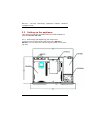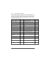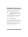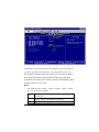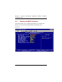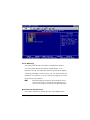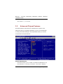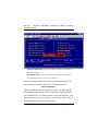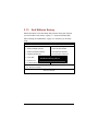
1
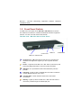
FASTORA NA- 1531/NA- 1801 Hardware Installation Guide For service person only Disclaimers The information in this manual has been carefully checked and is believed to be accurate. AXIOMTEK Co., Ltd. assumes no responsibility for any infringements of patents or other rights of third parties, which may result from its use. AXIOMTEK assumes no responsibility for any inaccuracies that may be contained in this document. AXIOMTEK makes no commitment to update or to keep current the information contained in this manual. AXIOMTEK reserves the right to make improvements to this document and/or product at any time and without notice. No part of this document may be reproduced, stored in a retrieval system, or transmitted, in any form or by any means, electronic, mechanical, photocopying, recording, or otherwise, without the prior written permission of AXIOMTEK Co., Ltd. Copyright 2004 by AXIOMTEK Co., Ltd. All rights reserved. Version A1 November 2004 Printed in Taiwan ii Safety Approvals u CE Marking u FCC Class A FCC Compliance This equipment has been tested and complies with the limits for a Class A digital device, pursuant to Part 15 of the FCC Rules. These limits are designed to provide reasonable protection against harmful interference in a residential installation. If not installed and used in accordance with proper instructions, this equipment might generate or radiate radio frequency energy and cause harmful interference to radio communications. However, there is no guarantee that interference will not occur in a particular installation. If this equipment does cause harmful interference to radio or television reception, which can be determined by turning the equipment off and on, the user is encouraged to try to correct the interference by one or more of the following measurers: Reorient or relocate the receiving antenna. Increase the separation between the equipment and receiver. Connect the equipment into an outlet on a circuit different from that to which the receiver is connected. Consult the dealer or an experienced radio/TV technician for help. Shielded interface cables must be used in order to comply with emission limits. iii Safety Precautions Before getting started, read the following important cautions. 1. Be sure to ground yourself to prevent static charge when installing the internal components. Use a grounding wrist strap and place all electronic components in any static-shielded devices. Most electronic components are sensitive to static electrical charge. 2. Disconnect the power cords from the NA-1531 / NA-1801 before making any installation. Be sure both the system and the external devices are turned OFF. Sudden surge of power could ruin sensitive components. Make sure the NA-1531 / NA-1801 is properly grounded. 3. Do not open the system’s top cover. If opening the cover for maintenance is a must, only a trained technician is allowed to do so. Integrated circuits on computer boards are sensitive to static electricity. To avoid damaging chips from electrostatic discharge, observe the following precautions: ü Before handling a board or integrated circuit, touch an unpainted portion of the system unit chassis for a few seconds. This will help to discharge any static electricity on your body. ü When handling boards and components, wear a wrist-grounding strap, available from most electronic component stores. Trademarks Acknowledgments AXIOM TEK is a trademark of AXIOM TEK Co., Ltd. Other brand names and trademarks are the properties of their respective owners. iv Table of Contents Chapter 1 Intoduction -----------------------------------8 1.1 1.2 1.3 1.4 1.5 1.6 1.7 General Description........................................ 8 Standard Features .......................................... 9 System Specifications .................................. 10 Dimensions .................................................. 13 Front Panel Outlets....................................... 14 Rear Panel Outlets........................................ 17 Indications of Front Panel … … … … … … … … … 17 Chapter 2 Installation Procedures --------------- 19 2.1 2.2 Preinstallation Checklist ............................... 19 Setting up the appliance ............................... 20 2.2.1 2.2.2 2.2.3 2.2.4 2.2.5 2.2.6 2.2.7 2.2.8 Removing and Replacing the Top Cover… … … ....... 2 0 Installing a Microprocessor (CPU) ... … … … … … … … 21 Installing a memory module (DIMM) ...... … … … … … ..21 Installing a DMA/66/100 hard drive .... … … … … … … .2 2 Connectors & Jumpers… .… … … … … … … … … … … … .23 Installation display interface… … … … … … … … … … … 2 5 Installation seria interface… … … … … … … … … … … … 2 6 Installing keyboard and PS/2 mouse connectors… … … … … … ..… … … … … … … … … … … ...26 2.2.9 Installing USB con nectors(optional) … … … … … ..… ..2 7 2.2.10 Installing and program LCDmodule … … … … … … .… .27 Chapter 3 Award BIOS Utility---------------------3 2 3.1 3.2 3.3 3.4 3.5 3.6 3.7 3.8 3.9 3.10 3.11 3.12 3.13 BIOS interduction… … … … … … … … … … … ..… … 32 BIOS setup… … … … … … … … … … … … … … … … … 32 Standard CMOS setup… … … … … … … … … … … ..34 Adavanced BIOS features … … … … … … … … … .38 Adavanced chipset features … … … ..… … … … .42 Integrated peripherals … … … … … … … … … … … 47 Power management setup … … … … … … … … .52 PNP / PCI Configuration … … … … … … … … … ..54 PC Health Status … … … … … … … … … … … … … .57 Load optimized defaults … … … … … … … … … … 58 Set supervisor / user password … … … … … … .59 Save & Exit Setup … … … … … … … … … … … … … 62 Quit without saving … … … … … … … … … … … … .63 Appendix A Warning ----------------------------------- 64 Table of Contents v vi This page does not contain any information. Table of Contents vii NA-1531 / NA-1801 Networking Application Platform Hardware Installation Guide Chapter1 Introduction This chapter contains the general information and the detailed specifications of the NA-1531 / NA-1801 Network Appliance server. Chapter 1 includes the following sections: n General Description n Mechanical Dimensions n Features n I/O Outlets n System Specifications 1.1 General Description The NA-1531 / NA -1801 server is designed for network software solution providers those have data secure, voice over IP, video streaming, network bandwidth controller and another networking appliance requirements across this stable and reliable multiple LAN device. It is a reliable and affordable, 1U-height unit that requires only power and network connections for setup. There can be deployed up to eight LAN ports combinations for customer selection in the maximum for application. They also can support LAN by-pass features which can isolate the defective segments. NA-1531 / NA-1801 has pretty good enclosure management interface to be implemented in the factory default. It can support P.O.S.T (Power On Self Test) feature through hyper-terminal by console port. LCD module function is available for customer coding also. 8 Introduction And it has room space for one hard drive deployment. Customer can implement system log and monitoring functions through this hardware specification. With its innovative mechanical and electrical design, the NA-1531 / NA-1801 server provides one PCI expansion slot for VPN encryption / decryption adapter board and another special functions enabling. It cans enhancement network security process performance and of-load the CP U loading. The NA-1531 / NA-1801 can support wonderful networking application platform by excellent cost with performance ratio. 1.2 Standard Features l 1 U-height rack -mount/stacked-up design l High performance Intel Pentium 4 processor l Five gigabit and three 100Mbps LAN ports combinations are for NA-1531. Eight gigabit LAN ports combinations are for NA-1801 . l Support BIOS redirected to COM port feature and LAN by -pass feature. l Support RS -232 and two USB l PCI- X 64-bit/ 66M Hz expansion slot for another network security encryption board l LCM setting functions is available l Supports Microsoft Networks, FreeBSD Linux and UNIX Networks Table of Contents 9 NA-1531 / NA-1801 Networking Application Platform Hardware Installation Guide 1.3 System Specifications Hardware l Form Factor: 1U rack -mount/stacked-up on desktop design l Capacity: It is from 0 to 250GB and beyond, depending on the 2.5 ” hard disk drive capacity. l Power Supply: Single 300W ATX HRP power supplies Standard ATX power input connector l Hard Drive: Spacing for 1 x IDE HDD (2.5 ”) l Rear Panel Connector: 8 x 10/100/1000 Base-T Ethernet LAN port (For NA -1801) 5 x 10/100/1000 Base-T and 3 x 10/100Mbps Ethernet LAN port (For NA -1531) 1 x C onsole port 2 x USB port l Front Panel LED: 1 x LED for HDDs 16 x LED for LANs (Ten of them are for per port Link and Activity, other of them are for per port transfer rate) 1 x Power LED for Syste m l Processor: Intel Pentium 4 processor up to 3 .4 GHz FSB 800 MHz 10 Introduction l BIOS: Award 4MB Flash BIOS Plug & Play l L2 Cache: Built-in in CPU l Main Memory: Two DDR266/DDR400 memory DIMM can be up to 2GB in the maximum l IDE Interface: Support two ATA 66/100/133 EIDE channels Support two S-ATA 1.0 channels l Serial Port: One U A R T l Ethernet: Totally has eight LAN port connections are available. Tw o ports of them support LAN by-pass feature , l Expansion: One PCI 64-bit/66Mhz for security encryption card o r specialize functions expansion l Compact-Flash TM : TM One IDE interface CompactFlash socket for embedded use l Dimensions: 428mm(19”)(W) x 4 4mm(1 .75”)(H) x 301mm(11 .8 5”)(D) l Weight: Approx. 8.5k g with Power supplies , without any hard drive l Operation environment: Air temperature: 10° C – 45°C (50°F – 113 °F) Humidity: 10% – 95% l Storage environment: Air temperature: -20° C – 70°C Humidity: 10% – 95% Table of Contents 11 NA-1531 / NA-1801 Networking Application Platform Hardware Installation Guide 12 Introduction 1.4 Dimensions Unit: mm Table of Contents 13 NA-1531 / NA-1801 Networking Application Platform Hardware Installation Guide 1.5 Front Panel Outlets Located at the front panel of the NA-1531 / NA-1801 server are the I/O outlets for connections of serial and Ethernet interface-supported devices. You also can find out the LCD module. The NA- 1531 / NA -1801 Server Rear Panel USB Port LCD Module Console Port LAN link / transfer rate Console port – DB-9 RS-232 Console port for command line interface and diagnostic support by P.O.S.T (Power On Self Test). Power – Lights when the NA-1531 / NA-1801 is powered up and performing diagnostic tests to check for proper operation. USB port – For specialize functions was defined by solution provider. LAN Link – Lights up with a Twisted pair connection is made to another Ethernet device on the port. Transfer Rate – Show network transfer rate while make connections Activity – Lights up when the NA-1531 / NA-1801 transmits or receives a packet through the twisted pair port 14 Introduction Table of Contents 15 NA-1531 / NA-1801 Networking Application Platform Hardware Installation Guide 1.6 Rear Panel Outlets Located at the rear panel of the NA-1531 / NA-1801 server are the I/O outlets. You will also find the main power switch and cooling fans. Power Switch 100-240VAC 50-60Hz Expansion slot Internal FANs Power input Expansion slot – To support one PCI-X 64-bit and 66Mhz slot which is for adapter card expansion 16 Introduction 1.7 I. Indications of Front Panel Power on LED 1. System and power on I. HDD LED Link/Active LED (single color) 1. The green LED is on when the HD has connection normally 2. The LED flashes when there is transmit or receive activity II. Link/Active LED (Single color)for LAN port #1, port#2, port#3, port#4, port#5, port#6, port#7 and port#8 1. The yellow LED is on when there is an active connection on the LAN port 2. The LED flashes when there is transmit or receive activity to or from the appliance 3. The LED is dark when it off line. III. Transmitted LED (Dual color) for LAN port #1, port#2, port#3, port#4, port#5, port#6, port#7 and port#8 1. The orange LED light is on 10/100/1000Mbps transfer rate Table of Contents 17 NA-1531 / NA-1801 Networking Application Platform Hardware Installation Guide 2. The green LED light is on 10 /100Mbps transfer rate 3. The LED is dark if the Link/Active LED is light or flash in the same time, It’s on 10Mbps transfer rate 4. The LED is dark if the Link/Active LED is dark also. There is no any networking device was attached. 18 Introduction Chapter 2 Installation Procedures 2.1 Preinstallation Checklist In addition to this installation guide, make sure you have the following items, n The NA-1531 / NA -1801 network appliance hardware platform n Power cord n Utility CD (including this installation guide) n Mounting screws for disk drive and screws used in this appliance for spare n Quick installation guide n Hardware Installation Guide n NA -1531 / NA -1801 cable kits (1 x 40 -pin IDE, 1 x console cable, 1 x S-ATA cable, 1 x PS/2 keyboard and mou se cable, 1 x VGA cable) n Mounting brackets for rack installation (left/right) x 2 n Plastic stand for stack – up x 4 If you ordered options for the appliance, this package might contain additional hardware or publications for those options. . Table of Contents 19 NA-1531 / NA-1801 Networking Application Platform Hardware Installation Guide 2.2 Setting up the appliance This section provides the information about the initial installation to setup the NA-1531 / NA -1801 2. 2 . 1 Removing and Replacing the Top Cover To gain access into the internal components of the NA-1531 / NA-1801, you must follow the instructions given below to remove the top cover. 20 Introduction uMain Board 2. 2 . 2 Installing a Microprocessor (CPU) 1. Align pin one (e.g., white dot) of the CPU with pin one of the socket. Pin one of the CPU socket may either be marked on the board or indicated by an arrow head symbol on one corner of the socket. Normally, its diagonal corner distinguishes pin one on the socket. 2. To complete the CPU installation, gently press the CPU into place. 3. Double-check the insertion and orientation of the CPU before appl ying power. Improper installation will result in permanent damage to the CPU. 2.2.3 Installing a memory module (DIMM) The main board can supports two 184-pin DDR socket for a maximum total memory up to 2GB None-ECC unbuffer Memory. The Intel 875 can support Single- and Dual-Channel Operation 1. In single-channel operation DIMM2 is disabled. Only DIMM1 need be added. 2. In dual-channel mode the memory populated in the two channels must be identical DIMM configurations. The configuration consists of the same number of physical rows or banks (1 or 2), row address bits, column address bits, the same technology part (128-Mb, 256-Mb, 512-Mb), and the same DRAM chip width (x4, x8). It is not necessary to match DIMM timings. A CL=2.0 DIMM can be paired with a CL=2.5 DIMM as long as the geometry matches. Attention: u When you handle electrostatic discharge-sensitive (ESDs), take precautions to avoid damage from static electricity. v The memory can support DDR266/DDR333/DDR400. Table of Contents 21 NA-1531 / NA-1801 Networking Application Platform Hardware Installation Guide .2.2.4 Installing a DMA/66/100 hard drive To accommodate the fast transfer rate of Ultra DMA/66/100, a cable (with 44 pin connectors on both ends) is necessary when installing Ultra DMA/66/100 drives. The NA-1531 / NA-1801, on this aspect, can support IDE hard drive and DOM (Disk on Module) deployment. It is through the IDE Connector (CN4, CN3) 22 Introduction 2. 2 . 5 Connectors & Jumpers The connectors allow the CPU card to connect with other parts of the system. Some problems encountered by your system may be a result from loose or improper connections. Ensure that all connectors are in place and firmly attached. The following table lists the function of each connector on the main board. Connectors Label Connectors Label Ethernet Connector 1 CN11 Primary IDE Connector CN4 Ethernet Connector 2 CN12 Secondary IDE Connector CN3 Ethernet Connector 3 CN13 COM1 CN19 Ethernet Connector 4 CN14 COM2 CN10 Ethernet Connector 5 CN15 COM 3 CN6 Ethernet Connector 6 CN16 COM 4 CN7 Ethernet Connector 7 CN 17 USB Port 1, 2 Connector R_USB1 Ethernet Connector 8 C N 18 USB Port 3, 4 Connector CN2 Fan Power Connector 1 FAN1 LED Connector CN5 Fan Power Connector 2 FAN2 184-Pin DDR Memory Socket 1 DDR1 Fan Power Connector 3 FAN3 184-Pin DDR Memory Socket 2 PCI-X 64bit Slot SLOT1 Socket 478 CPU Socket A TX12V CPU Power Connector ATX Power Connector Mini-PCI Connetcor DDR2 SOCKET_1 ATX_12V1 System BIOS ATX1 U8 Compact Flash Card Slot CN1 J1 Internal Battery BAT1 Internal Keyboard Connector CN8 Internal Buzzer BU1 Internal Mouse Connector CN9 Serial ATA Connecter 1 S _ATA1 Serial ATA Connecter 2 Table of Contents S_ATA2 23 NA-1531 / NA-1801 Networking Application Platform Hardware Installation Guide Jumper Jumper Setting JP1 CF Card Voltage Setting : 3V Short 1-2 JP2 CF Card Master/Slave Setting : Master Short 1-2 PICMG Slot Usage Setting: Normal PCI-X Short 1-2 JP 6 PICMG Slot VIO setting : 3V Short 1-2 4-5 7-8 JP 7 CMOS Clear Jumper: Normal Mode Short 1-2 JP 14 LAN By -PASS : DISABLE Open J P 15 RS232 Setting Short 3-5 4-6 J P 16 RS232 Setting Short 1-2 7-8 J P 17 RS232 Setting Short 3-5 4-6 JP3,4, 5 24 Default Setting Introduction 2.2. 6 Installing Display Interface 2. 2. 6.1 CRT Interface In general, the customer need to have VGA display features while they making the software porting. The main boards of NA-1531 and NA-1801 both have supported a Mini-PCI slot. The customer can enable the VGA display features through AX92101 which is a mini-PCI bus VGA card. The Mini-PCI card can support CRT, LVDS and TFT. The customer also can use the third party VGA display adapter card through the PCI slot. 2.2. 7 Installing Serial Port Interface The serial interface onboard consists of COM1 port (CN19), COM2 (CN10), COM3 (CN6) and COM4 (CN7) supports RS-232. These interfaces could be for LCM command transaction bus or another specifies features applications by customer. 2. 2. 7.1 Serial Ports IRQ Selection This main board uses four 10-pin connectors for COM1 (CN19), COM2 (CN10), COM3 (CN6) and COM4 (CN7). In general, we use the COM 2 to communicate with LCD module which like as a command channel to LCD module by software programming. As for the COM 1, it should be a console port for this device. Which way can supports customer doing self test or diagnostic to this device. Power Supply Specifications 25 NA-1531 / NA-1801 Networking Application Platform Hardware Installation Guide Interrupt Requests on COM1 and COM2 are selected via IRQ4 and IRQ3 respectively. Additionally, both ports can be enabled or disabled via BIOS setting. RS-232/422/485 PIN Assignment: COM1,COM2, COM3 and COM4 COM1 D-SUB Description RS-232 COM2 9PIN 1 1 Data Carrier Delect(DCD) 2 6 Data Set Ready(DSR) 3 2 Receive Date(RXD) 4 7 Request to Send(RTS) 5 3 Transmit Data(TXD) 6 8 Clear to Send(CTS) 7 4 Data Terminal Ready (DTR) 8 9 Ring Indicator(RI) 9 5 GND 10 X NC 2.2. 8 Installing Keyboard and PS/2 Mouse Connectors The NA -1301 provides External keyboard (CN8) and Mouse (CN9) interface with two 5-pin connectors for porting software easily by customer. CN8/CN9 26 Starting the Appliance Data 4 5 Power Clock 3 GND 2 No Connection 1 2.2. 9 Installing USB Connector (Optional) The Universal Serial Bus (USB) connector on the main board is for installation of peripherals supporting the USB interface. R_USB1 /CN2 are the 10-pin USB connector on the main board. 2.2.10 I nstall ing and Program LCD Module 1. Working flow Communicate with PC through console cable Power Supply Specifications 27 NA-1531 / NA-1801 Networking Application Platform Hardware Installation Guide a) Baud Rate = 9600 b) Data Bits = 8 c) Stop Bits = 2 d) Parity Check = None In fact, the COM Port is only use two signal as Tx and & Rx in data transaction The LCD module model name was called AX89063. The PC with AX89063 connection is should be PIN To PIN assignment. The LCD is “16 by 2”,it show 16 words in each row. And can show totally 32 words with two rows. 2. Data transfer format A) command: 0D hex:PC à AX89063 It moves the cursor to the entry point (on left upper corner of LCM)。 Attention: It is just move the RAM flag to point out into the entry point of LCM. It needs to be progress this commands about 40μs。 If we need to clear the contents in show up, it needs to be progress this commands about 1.6ms。 28 Starting the Appliance The transfer rate should be 1.15msec per byte if we use baud rate as 9600. So the time interval should be 0.5msec for next commands initialization 。 B) data:PC à AX89063 The showing data total length should be 80 Bytes of LCM, supposedly.。But, it is only can display 1 to 16 words and 41 to 56 words。 If would like to show the words with two rows of LCM, the PC need to send the 80 bytes totally。 The each character will be fill in into the RAM of LCM which it was initialized through the console port。 For example: The PC sends following string to LCM which is totally 80 characters String = Welcome>>AX89063************************Test>Progra m>>>>************************ LCM will display strings as following, Welcome>>AX89063 Test>Program >>>> Power Supply Specifications 29 NA-1531 / NA-1801 Networking Application Platform Hardware Installation Guide As for the ‘*’character, therefore it doesn’t show off in the LCM. But it will be stored in the RAM of LCM。 C) Keypad data:AX89063 à PC a) ▲ ( Up ):when it was press then release, the LCM will send 55hex to PC,It is ASCII code for ’U’。 b) ▼ ( Down ):when it was press then release,the LCM will send 44hex to PC,it is ASCII code for ’D’。 c) ESC:when it was press then release, the LCM will send 4Chex to PC,it is ASCII code for ’L’。 d) Enter:when it was press then release, the LCM will send 52hex to PC,it is ASCII code for ’R’。 3. Fronts table of LCM: ( as following figure ) The front type display is following internal front table of LCM ,the ASCII code for English characters and Arabic numerals is same as with PCs。 For special symbols, the PC must send concurrent characters to LCM. Then it can show off the right information。 30 Starting the Appliance Power Supply Specifications 31 NA-1531 / NA-1801 Networking Application Platform Hardware Installation Guide Chapter3 Award BIOS Utility Chapter 4 describes the different settings available in the Award BIOS that comes with the NA-1531 / NA-1801. Also contained here are instructions on how to set up the BIOS configuration. 3.1 BIOS Introduction The Award BIOS (Basic Input/Output System) installed in your computer system’s ROM supports Intel Celeron processors in a standard IBM -AT compatible I/O system. The BIOS provides critical low-level support for standard devices such as disk drives, serial and parallel ports. It also adds virus and password protection as well as special support for detailed fine-tuning of the chipset controlling the entire system. 3.2 BIOS Setup The Award BIOS provides a Setup utility program for specifying the system configurations and settings. The BIOS ROM of the system stores the Setup utility. When you turn ON the computer, the Award BIOS is immediately activated. Pressing the <Del> key immediately allows you to enter the Setup utility. If you are a little bit late pressing the <Del> key, POST (Power On Self Test) will continue with its test 32 Starting the Appliance routines, thus preventing you from invoking the Setup. If you still wish to enter Setup, restart the system by pressing the ”Reset” button or simultaneously pressing the <Ctrl>, <Alt> and <Delete> keys. You can also restart by turning the system OFF and back ON again. The following message will appear on the screen: Press <DEL> to Enter Setup In general, you press the arrow keys to highlight items, <Enter> to select, the <PgUp> and <PgDn> keys to change entries, <F1> for help and <Esc> to quit. When you enter the Setup utility, the Main Menu screen will appear on the screen. The Main Menu allows you to select from various setup functions and exit choices. Power Supply Specifications 33 NA-1531 / NA-1801 Networking Application Platform Hardware Installation Guide The section below the setup items of the Main Menu displays the control keys for this menu. Another section located at the bottom of the Main Menu, just below the control keys section, displays information on the currently highlighted item in the list. NOTE: If you find that your computer cannot boot after making and saving system changes with Setup, the Award BIOS, via its built- in override feature, resets your system to the CMOS default settings. We strongly recommend that you avoid making any changes to the chipset defaults. These defaults have been carefully chosen by both Award and your system manufacturer to provide the absolute maximum performance and reliability. 3.3 Standard CMOS Setup “Standard CMOS Setup” allows you to record some basic hardware configurations in your computer system and set the system clock and error handling. If the motherboard is already installed in a working system, you will not need to select this option. You will need to run the Standard CMOS option, however, if you change your system hardware configurations, the onboard battery fails, or the configuration stored in the CMOS memory was lost or damaged. 34 Starting the Appliance At the bottom of the menu are the control keys for use on this menu. If you need any help in each item field, you can press the <F1> key. It will display the relevant information to help you. The memory display at the lower right-hand side of the menu is read-only. It will adjust automatically according to the memory changed. The following pages describe each item of this menu. Date The date format is <day>, <date> <month> <year>. Press <F3> to show the calendar. day The day of week, from Sun to Sat, determined by the BIOS, is read only date The date, from 1 to 31 (or the maximum allowed in the month), can key in the numerical / function key The month, Jan through Dec. month Power Supply Specifications 35 NA-1531 / NA-1801 Networking Application Platform Hardware Installation Guide year The year, depends on the year of BIOS Time The time format is <hour> <minute> <second> accepting either function key or numerical key. The time is calculated based on the 24-hour military -time clock. For example, 1 p.m. is 13:00:00. Primary Master/Primary Slave/Secondary Master/Secondary Slave The categories identify the types of one channel that have been installed in the computer. There are 45 predefined types and 2 user definable types are for Enhanced IDE BIOS. Type 1 to Type 45 are predefined. Type User is user-definable. Press <PgUp>/<+> or <PgDn>/< −> to select a numbered hard disk type or type the number and press <Enter>. Note that the specifications of your drive must match with the drive table. The hard disk will not work properly if you enter improper information within this category. If your hard disk drive type does not match or is not listed, you can use Type User to define your own drive type manually. If you select Type User, related information is asked to be entered to the following items. Enter the information directly from the keyboard and press <Enter>. This information should be provided in the documentation from your hard disk vendor or the system manufacturer. If the controller of HDD interface is ESDI, select “Type 1”. 36 Starting the Appliance If the controller of HDD interface is SCSI, select “None”. If the controller of HDD interface is CD-ROM, select “None”. CYLS. HEADS number of cylinders number of heads LANDZONE SECTORS landing zone number of sectors PRECOMP write precom MODE HDD access mode If there is no hard disk drive installed, select NONE and press <Enter>. Halt On This field determines whether the system will halt if an error is detected during power up. No errors The system boot will halt on any error detected. (default) All errors Whenever the BIOS detects a non-fatal error, the system will stop and you will be prompted. The system boot will not stop for a keyboard error; it will stop for all other errors. The system boot will not stop for a disk error; it will stop for all other errors. The system boot will not stop for a keyboard or disk error; it will stop for all other errors. All, But Keyboard All, But Diskette All, But Disk/Key Power Supply Specifications 37 NA-1531 / NA-1801 Networking Application Platform Hardware Installation Guide 3.4 Advanced BIOS Features This section allows you to configure and improve your system and allows you to set up some system features according to your preference. 38 Starting the Appliance Virus Warning This item protects the boot sector and partition table of your hard disk against accidental modifi cations. If an attempt is made, the BIOS will halt the system and display a warning message. If this occurs, you can either allow the operation to continue or run an anti-virus program to locate and remove the problem. NOTE: Many disk diagnostic programs, which attempt to access the boot sector table, can cause the virus warning. If you will run such a program, disable the Virus Warning feature. Quick Power On Self Test This option speeds up Power On Self Test (POST) after Power Supply Specifications 39 NA-1531 / NA-1801 Networking Application Platform Hardware Installation Guide you turn on the system power. If set as Enabled, BIOS will shorten or skip some check items during POST. The default setting is “Enabled” . Enabled Enable Quick POST Disabled Normal POST First/Second/Third Boot Device st nd These items allow the selection of the 1 , 2 , and 3 rd devices that the system will search for during its boot -up sequence. The wide range of selection includes Floppy, LS120, ZIP100, HDD0~3, SCSI, and CDROM. Boot Other Device This item allows the user to enable/disable the boot device not listed on the First/Second/Third boot devices option above. The default setting is Enabled. Boot Up NumLock Status This option enables and disables the numberlock function of the keypad. The default value is “On”. On Keypad functions confine with numbers Off Keypad functions convert to s pecial functions (i.e., left/right arrow keys) . Security Option This item allows you to limit access to the system and Setup, or just to Setup. The default value is “Setup”. 40 Starting the Appliance System Setup NOTE: The system will not boot and access to Setup will be denied if the incorrect password is entered at the prompt. The system will boot, but access to Setup will be denied if the correct password is not entered at the prompt. To disable security, select PASSWORD SETTING at Main Menu and then you will be asked to enter password. Do not type anything, just press <Enter> and it will disable security. Once the security is disabled, the system will boot and you can enter Setup freely. MPS Version Control For OS This item allows you to select the version of MPS table for NT 4.0. The choice: 1.1, 1.4 OS Select for DRAM > 64MB This segment is specifically created for OS/2 when DRAM is larger than 64MB. If your operating system is OS/2 and DRAM used is larger the 64MB, you have to select “OS 2”, otherwise (under non-OS2), default is NON -OS2. The default value is “ Non-O S 2” . Agent Connect via This item is just highlight the routing between console port with PC client. The default value should be Null. Agent Waiting Time This item is just highlight the polling timer. If the cons ole port doesn’t receive the inquiry from PC client in the time frame. It will be cut out the monitoring path for BIOS booting from console. The default value should be 1 minutes. Power Supply Specifications 41 NA-1531 / NA-1801 Networking Application Platform Hardware Installation Guide The choice: 1, 2, 4 and 8 3.5 Advanced Chipset Features Since the features in this section are related to the chipset on the CPU board and are completely optimized, you are not recommended to change the default settings in this setup table unless you are well oriented with the chipset features. Console Redirection This item allows you to enable or disable the BIOS boot up and redirect to console port feature. The choice: Enable, 42 Starting the Appliance Disable Baud Rate This item allows you to setup the data transfer rate for the console port. The default value is 9600. The choice: 9600, 19200, 38400, 57600 and 115200 Agent After Boot This item allows you to enable or disable the agent after boot. The choice: disable, enable DRAM Timing Control Press “Enter” setting DRAM timing as below. CAS Latency Time When synchronous DRAM is installed, the number of clock cycles of CAS latency depends on the DRAM timing. The Choice: 1.5, 2, 2.5. Active to Precharge Delay This item controls the number of DRAM clocks for TRAS. The Choice: 7, 6, 5. DRAM RAS# to CAS# Delay This field let ’s you insert a timing del ay between the CAS and RAS strobe signals, used when DRAM is written to, read from, or refreshed. Fast gives faster performance; and Slow gives more stable performance. This field applies only when synchronous DRAM is installed in the Power Supply Specifications 43 NA-1531 / NA-1801 Networking Application Platform Hardware Installation Guide system. The Choice: 3, 2. DRAM RAS# Precharge If an insufficient number of cycles is allowed for the RAS to accumulate its charge before DRAM refresh, the refresh may be incomplete and the DRAM may fail to retain data. Fast gives faster performance; and Slow gives more stab le performance. This field applies only when synchronous DRAM is installed in the system. The Choice: 2, 3. System BIOS Cacheable: The ROM BIOS can be mapping to the addresses as F0000h to FFFFFh pass through buffer cache; it can speed up access time of BIOS. But most of OS doesn’t inquiry through BIOS in operating, and some of programs maybe occupied the segment of address. so we recommend the default value should be disabled. The Choice: Enabled, Disabled Memory Hole at 15M-16M: (Reserved segment of memory for memory.) Some of expansion adapter card will allocate some segment of memory in operating. We can release 15M address above to 44 Starting the Appliance task progressing if we enabled the function. But, the most of OS doesn’t use the segment of memory in progressing. The factory default should be disabled. The choice: Enabled, Disabled. Delay Prior to Thermal: When the CPU over heating than temperature setting of factory default, the clock will be postponed. Then the temperature monitoring function also will be enabled right away. The clock module of thermal diode also be trigged which way to keeping the temperature limitation. The choice: 4 Min,8 Min,16 Min,32 Min 。 AGP Aperture Size(MB): (AGP Local memory spacing, MB) The AGP will share addressing of system memory for display purpose. We suggest the AGP local memory doesn’t beyond 64MB to 128MB. The choice: 4、8、16、32、64、128 、256 Init Display First: We can select the VGA device in booting which is from on board VGA chipset or AGP or other PCI slots, If the interface default setting doesn’t have VGA device. The BIOS will automatically switch to another VGA devices. The choice: Onboard, AGP, PCI Slot. DRAM Data Integrity Mode: Power Supply Specifications 45 NA-1531 / NA-1801 Networking Application Platform Hardware Installation Guide The ECC(Error Checking and Correction)mode adopted extra 72-bit to check the data integrity. It can correct one bit error. We can make the system stability and reliability by this way accordingly. If you doesn’t have ECC memory deployment, you can set the value to be Non-ECC. The choice: ECC, Non -ECC Spread Spectrum This item allows you to enable/disable the spread spectrum modulate. The choice: 46 Enabled, Disabled. Starting the Appliance 3.6 Integrated Peripherals This option sets your hard disk configuration, mode and port. On-Chip Primary/Secondary PCI IDE The integrated peripheral controller contains an IDE interface with support for two IDE channels. Select Enabled to activate each channel separately. The choice: Enabled, Disabled. IDE Primary/Secondary Master/Slave PIO The four IDE PIO (Programmed Input/Output) fields let you set a PIO mode (0-4) for each of the four IDE devices that the onboard IDE interface supports. Modes 0 through 4 provide successively increased performance. In Auto mode, the system automatically determines the best mode for Power Supply Specifications 47 NA-1531 / NA-1801 Networking Application Platform Hardware Installation Guide each device. The choice: Auto, Mode 0, Mode 1, Mode 2, Mode 3, Mode 4. IDE Primary/Secondary Master/Slave UDMA Ultra DMA/33 implementation is possible only if your IDE hard drive supports it and the operating environment includes a DMA driver (Windows 98 or a third-party IDE bus master driver). If your hard drive and your system software both support Ultra DMA/33, select Auto to enable BIOS support. The Choice: Auto, Disabled. On-Chip Primary/Secondary Serial ATA The integrated peripheral controller contains an S -ATA interface with support for two S-ATA channels. Select Enabled to activate each channel separately. The choice: Enabled, Disabled. USB Controller Select Enabled if your system contains a Universal Serial Bus (USB) controller and you have USB peripherals. The choice: Enabled, Disabled. USB 2.0 Controller Select Enabled if your system contains a Universal Serial Bus V2.0 (USB2.0) control ler and you have USB2.0 48 Starting the Appliance peripherals. The choice: Enabled, Disabled. USB Keyboard Support Select Enabled if your system contains a Universal Serial Bus (USB) controller and you have a USB keyboard. The choice: Enabled, Disabled. USB Mouse Support Select E nabled if your system contains a Universal Serial Bus (USB) controller and you have a USB Mouse. The choice: Enabled, Disabled. Onboard Serial Port 1/Port 2 Select an address and corresponding interrupt for the first and second serial ports. The choice: 3F8/IRQ4, 2E8/IRQ3, 3E8/IRQ4, 2F8/IRQ3, Disabled, Auto. UART Mode Select This item allows you to select UART mode. The choice: IrDA, ASKIR, Normal. UR2 duplex mode This item can control the progressing mode for transmission and receive for IR. The setting should have the full duplex and half duplex. In full duplex mode, it can be allowed sync, two way transmission and receive. In half duplex mode, it only supports the async, two way transmission and receives. Power Supply Specifications 49 NA-1531 / NA-1801 Networking Application Platform Hardware Installation Guide POWER ON Function This option allows users to select the type of power ON sequence for the system to follow. The default value is “ Button -Only” . BUTTON-ONLY Password Hot KEY Follows the conventional way of turning OFF system power (via power button). Upon selecting this option, the KB POWER ON Password line appears. Press <Enter> and you’ll be prompted to enter and confirm a password of your choice. After setting the password, succeeding attempts to power ON the system will result to null. For system to activate, user must input the password via keyboard then press <Enter>. This option is very similar with that of Password. Hot-key combinations range from Ctrl-F1 to Ctrl-F12. User may define this combination from the Hot key Power ON option. KB Power ON Password This item allows you to set the keyboard power on password. 50 Starting the Appliance Hot Key Power On This item allows you to select the hot key of the keyboard power on. The choice: Ctrl-F1~F12. Onboard Serial Port 1/Port 2 Select an address and corresponding interrupt for the first and second serial ports. The choice: 3F8/IRQ4, 2E8/IRQ3, 3E8/IRQ4, 2F8/IRQ3, Disabled, Auto. UART Mode Select This item allows you to select UART mode. The choice: IrDA, ASKIR, Normal. RxD, TxD Active This item allows you to determine the active of RxD, TxD. The Choice: “Hi, Hi”, “Lo, Lo”, “Lo, Hi”, “Hi, Lo ”. PWRON After PWR-Fail This item allows you to select if you want to power on the system after power failure. The choice: Off, On, Former-Sts. Power Supply Specifications 51 NA-1531 / NA-1801 Networking Application Platform Hardware Installation Guide 3.7 Power Management Setup The Power Management Setup allows you to save energy of your system effectively. It will shut down the hard disk and turn OFF video display after a period of inactivity. ACPI Function This item allows you to enable/disable the Advanced Configuration and Power Management (ACPI). The choice: Enabled, Disabled. Power Management This item allows you to select the Power Management 52 Starting the Appliance mode. The choice: User Define, Min Saving, Max Saving. Video Off Method In suspending, this item allows you to select the CRT closed method under APM mode. The choice: Blank Screen, V/H SYNC+Blank, DPMS Video Off In Suspend In suspending, this item allows you to select if you want to close the CRT under APM mode. The choice: Enabled, Disabled. Suspend Mode When enabled and after the set time of system inactivity, all devices except the CPU will be shut off. The choice: Enabled, Disabled. HDD Power Down When enabled and after the set time of system inactivity, the hard disk drive will be powered down while all other devices remain active. The choice: Enabled, Disabled. Resume by Alarm When Enabled, your can set the date and time at which the RTC (real-time clock) alarm awakens the system from Suspend mode. The choice: Enabled, Disabled. FDD, COM, LPT Port Power Supply Specifications The default value is “Disabled”. 53 NA-1531 / NA-1801 Networking Application Platform Hardware Installation Guide 3.8 PNP/PCI Configuration This section describes configuring the PCI bus system. PCI, or Personal Computer Interconnect, is a system which allows I/O devices to operate at speeds nearing the speed the CPU itself uses when communicating with its own special components. This section covers some very technical items and it is strongly recommended that only experienced users should make any changes to the default settings. Reset Configuration Data 54 Starting the Appliance Normally, you leave this field Disabled. Select Enabled to reset Extended System Configuration Data (ESCD) when you exit Setup or if you have installed a new add-on and the system reconfiguration has caused such a serious conflict that the operating system can not boot. The options available are Enabled and Disabled. Resource controlled by The Award Plug and Play BIOS has the capacity to automatically configure all of the boot and Plug and Play compatible devices. However, this capability means absolutely nothing unless you are using a Plug and Play operating system such as Windows 98. The options available are Auto and Manual. IRQ Resources When resources are controlled manually, assign each system interrupt a type, depending on the type of device using the interrupt. Power Supply Specifications 55 NA-1531 / NA-1801 Networking Application Platform Hardware Installation Guide PCI/VGA Palette Snoop Leave this field at Disabled. The choice: Enabled, Disabled. 56 Starting the Appliance 3.9 PC Health Status This option configures the PCI bus system. All PCI bus systems on the system use INT#, thus all installed PCI cards must be set to this value. Current System Temp. Show you the current system temperature. Current CPU1 Temperature Show you the current CPU1 temperature. Current FAN1/FAN2/FAN3 Speed These optional and read-only fields show the current speeds in RPM (revolution per minute) for the CPU fan and chassis fan as monitored by the hardware monitoring IC. Power Supply Specifications 57 NA-1531 / NA-1801 Networking Application Platform Hardware Installation Guide Vcc3/Vcore/2.5V/VCC/VBAT/5VSB/+12V Show you the voltage of Vcc3/Vcore/2.5V/VCC/VBAT/ 5VS B/+12V. 3.10 Load Optimized Defaults This option allows you to load the default values to your system configuration. These default settings are optimal and enable all high performance features. To load SETUP defaults value to CMOS SRAM, enter “Y”. If not, enter “N”. 58 Starting the Appliance 3.11 Set Supervisor/User Password You can set either supervisor or user password, or both of then. The differences between are: Power Supply Specifications 59 NA-1531 / NA-1801 Networking Application Platform Hardware Installation Guide supervisor password: can enter and change the options of the setup menus. user password: just can enter but do not have the right to change the options of the setup menus. When you select this function, the following message will appear at the center of the screen to assist you in creating a password. ENTER PASSWORD: Type the password with eight characters at most, and press <Enter>. The password typed will now clear any previously entered password from CMOS memory. You will be asked to confirm the password. Type the password again and press <Enter>. You may also press <Esc> to abort the selection and not enter a password. 60 Starting the Appliance To disable password, just press <Enter> when you are prompted to enter password. A message will confirm the password being disabled. Once the password is disabled, the system will boot and you can enter Setup freely. PASSWORD DISABLED. When a password is enabled, you have to type it every time you enter Setup. This prevents any unauthorized person from changing your system configuration. Additionally when a password is enabled, you can also require the BIOS to request a password every time the system reboots. This would prevent unauthorized use of your computer. You determine when the password is required within the BIOS Features Setup Menu and its Security option. If the Security option is set to “System”, the password is required during boot up and entry into Setup. If set as “Setup”, prompting will only occur prior to entering Setup. Power Supply Specifications 61 NA-1531 / NA-1801 Networking Application Platform Hardware Installation Guide 3.12 Save & Exit Setup This allows you to determine whether or not to accept the modifications. Typing “Y” quits the setup utility and saves all changes into the CMOS memory. Typing “N” brigs you back to Setup utility. Phoenix – AwardBIOS CMOS Setup Utility Standard CMOS Features } } Frequency/Voltage Control } Advanced BIOS Features Load Fail-Safe Defaults } Advanced Chipset Features Load Optimized Defaults } Integrated Peripherals Set Supervisor Password } Power Man } PnP/PCI Con } SAVE to CMOS and EXIT (Y/N)? Y PC Health Status Esc : Quit F10 : Save & Exit Setup Exit Without Saving á â à ß : Select Item Save Data to CMOS 62 Starting the Appliance 3.13 Quit Without Saving Select this option to exit the Setup utility without saving the changes you have made in this session. Typing “Y” will quit the Setup utility without saving the modifications. Typing “N” will return you to Setup utility. Phoenix – AwardBIOS CMOS Setup Utility Standard CMOS Features } } Frequency/Voltage Control } Advanced BIOS Features Load Fail-Safe Defaults } Advanced Chipset Features Load Optimized Defaults } Integrated Peripherals Set Supervisor Password } Power Man } PnP/PCI Con } Quit Without Saving (Y/N)? N PC Health Status Exit Without Saving á â à ß : Select Item Esc : Quit F10 : Save & Exit Setup Abandon all Datas Power Supply Specifications 63 NA-1531 / NA-1801 Networking Application Platform Hardware Installation Guide Appendix A Warning l This is a class A Product. In a domestic Environment this Product may cause radio interference in which case the user may be required to take adequate measures. l It will be danger if battery is incorrectly replaced. Replacing only with the same or equivalent type is highly recommended by the manufacturer. Dispose of used batteries according to the manufacturer’s instructions. l Warning for Hard Disk Drive Selection: TUV approved Hard Disk Drive is preferred for TUV compliance Hard Disk drive-Optional, (NWGQ2), generic, Input Voltage rated 5V dc/1.0A, 12V dc/1.8A maximum. Minimum clearance from uninsulated live parts 4.0 mm. “The equipment is to be installed in an environment with maximum ambient temperature must not exceed 40°C.” “The openings on the enclosure are for air convection hence protected the equipment from overheating. DO NOT COVER THE OPENINGS.” 64 Warning “Lay this equipment on a reliable surface when install. A drop or fall could cause injury.” “The equipment shall be installed according to specification as nameplate. Make sure the voltage of the power source when connect the equipment to the power outlet. The current of load and output power of loads shall be not over the specification.” “This equipment must be connected to the reliable earthing before using.” Electric shock hazard inside the redundant power supply The exchange of modules shall be done by service person. Warning 65 This page does not contain any informati on. 66