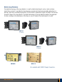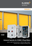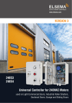
1
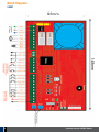
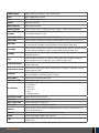
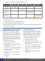
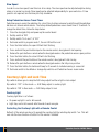
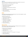
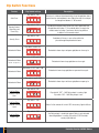
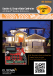
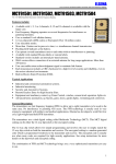
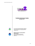
www.elsema.com
VERSION 3
240S1
240S2
Controller Card for 240VAC Motors
used on Light Commercial Doors, Industrial Roller Shutters,
Sectional Doors, Garage Doors, Sliding Doors and Swing Gates
Features
• Adjustable auto close
• Adjustable slow speed for open and close
• Dead man controls for open and close inputs
• Automatic ground and travel distance calibration
• Photocell, pedestrian and wireless remote control inputs
• External key switch for safety and security (Only on 240S2)
• Supports NC or NO limit switch inputs or travel timer setup
• Aux relay output to control courtesy lights and other accessories
• 24VDC output to supply external accessories such as loop detectors, swipe cards etc
• Toroidal transformer for excellent efficiency and low leakage losses reducing your electricity
consumption. Dynamic Power Savings
• Customised models available upon request, 120S1 and 120S2 for international markets
Description
The 240S1 and 240S2 are very similar cards except for the card size and the 240S2 has a key
switch input. Offering two different sizes allows the cards to be easily installed into existing cases as
replacement or upgrade cards. These two cards are one of our best valued cards on the market, selling
for a very competitive price, yet still loaded with many features.
The control cards were built from the ground up, based on customer feedback and using today’s
technology. With its rich functions, consumer friendly price and with the focus during development
being ease of use and setup makes these 240VAC control cards the ultimate board to control your motors.
A toroidal transformer is used to power the control card and contactors. Using a toroidal transformer
offers the following advantages:
• Excellent efficiency and low leakage losses reducing your electricity consumption
• High isolation which protects the electronics from noisy power lines
• Low magnetic field radiation and no acoustic noise enabling the controller to pass EMC and other
stringent radiation tests
Important warning and safety instructions
All installations and testing must be done only after reading and understanding all instructions carefully.
All wirings should be done only by trained technical personnel. Failing to follow instructions and the
safety warnings may result in serious injury and/or damage to property.
Elsema Pty Ltd shall not be liable for any injury, damage, cost, expense or any claim whatsoever to any
person or property which may result from improper use or installation of this product.
2
Controller Card for 240VAC Motors
Part Numbers:
Part Number
240S1E
Description
The 240S1E is enclosed in a compact IP66 rated plastic
enclosure. Case Size: 175 x 175 x 75mm
120S1E - 120VAC version for international markets with
120VAC Voltage
240S2E
The 240S2E is enclosed in a IP66 rated plastic enclosure with
UP / DOWN / STOP external push buttons.
120S2E - 120VAC version for international markets with
120VAC Voltage
240S2EK
The 240S2EK is enclosed in a IP66 rated plastic enclosure with
UP / DOWN / STOP external push buttons and key switch for
extra security and safety.
120S2EK - 120VAC version for international markets with
120VAC Voltage
Application
Light Commercial Doors, Industrial
Roller Shutters, Sectional Doors,
Garage Doors, Sliding Doors and
Swing Gates
Light Commercial Doors, Industrial
Roller Shutters, Sectional Doors,
Garage Doors, Sliding Doors and
Swing Gates
Light Commercial Doors, Industrial
Roller Shutters, Sectional Doors,
Garage Doors, Sliding Doors and
Swing Gates
The 240S1 control card only with board size of 148 x 92mm.
240S1
240S2
120S1 - 120VAC version for international markets with
120VAC Voltage
The 240S2 control card only with board size of 148 x 120mm
and key switch input.
120S2 - 120VAC version for international markets with
120VAC Voltage
Replacement or upgrade controller card
for 240VAC Motors
Replacement or upgrade controller card
for 240VAC Motors
All these controllers are suitable for motors up to 1.5kW (2.0Hp).
Risk in the goods purchased shall unless otherwise agreed in written pass to the buyer upon delivery of
the goods.
Any figures or estimates given for performance of goods are based upon the company’s experience and
is what the company obtains on tests. The company will not accept liability for failure to comply with
the figures or estimates due to the nature of variable conditions affecting for example Radio Remote
Controls.
Please keep this setup instruction for future reference.
www.elsema.com
3
Block Diagram
240S1
4
Controller Card for 240VAC Motors
240VAC Supply
Supply connection to power the 240S1 and the motor
Open
Motor OPEN direction terminal
Close
Motor CLOSE direction terminal
Neutral
Motor neutral terminal
Motor Capacitor
Motor capacitor terminal
Auxiliary Output
Used to connect a lock or courtesy light. Relay Contacts, Common and Normally Open
Limit Switch Open & If limit switches are used connect them to this terminal. Common
Factory Default Normally Closed
Limit Switch Close
If limit switches are used connect them to this terminal
Push Button
Used to connect an external push button to operate the gate or door. Normally open input.
Open Only
Used to connect an external push button to open the gate or door. With this input gate or door
can not be closed. Holding this input will prevent closing. Normally Open input.
Close Only
Used to connect an external push button to close the gate or door. With this input gate or door
can not be opened. Holding this input will prevent opening. Normally Open input.
Common
Common terminal for any of the inputs, including push button, open only, close only, stop
and pedestrian access.
Stop
Used to connect an external push button to stop the gate or door. Holding this input will
prevent the gate or door from opening or closing. Normally Open input.
Pedestrian Access
Used to connect an external push button to open gate or door partially for pedestrian access.
Normally Open input.
Photo Electric Beam
Used to connect a photo electric beam. Factory Default is Normally Closed input. User can
change to Normally Open.
DC Output
24VDC / 150mA. Use to supply accessories.
(Use Elsema Reg12 to convert this output to 12VDC)
Slide Switch
Used to access the control card features.
Input Status LEDs
Indicates inputs status.
Tact Switches
Test button for inputs in RUN mode and used to access the features in program mode.
A = Push Button
B = Open Only
C = Close Only
D = Stop
E = Pedestrian Access
Auto Close trimpot
Used to adjust the Auto Close time.
Dip Switch
Used to access the control card features.
Open, Close LEDs
Indicates Opening or Closing cycle.
Enter button
Used to change features in programming mode.
Receiver
Used to connect Elsema’s receivers to operate the control card with a remote control. Use
Elsema’s Pentacode series.
Antenna
Used to connect an external antenna for the plug in receiver.
Buzzer
Indicates that change of features was successful.
Fuse
Slow blow 5 Amps fuse. Replace fuse with a slow blow 10 Amps if using a motor larger than
1.0kW (1.3HP).
www.elsema.com
5
Block Diagram
240S2
120mm
FUSE
240Volts
AC Supply
Neutral
M
Earth
Close
Active
Open
Neutral
Motor
Capacitor
Motor
Capacitor
Normally Closed
User can change to
Normally Open
148mm
Relay
Output NO
Output C
Open Limit
Common
Close Limit
A
Push Button
B
Open Only
C
Close Only
ON
1
2
Common
3
4
Common
5
6
D
Stop
7
E
8
Photo Beam
DC Output +
DC Output -
Open
Close
Normally Closed
User can change
PED Access
Shield
Antenna
R
e
c
e
i
v
e
r
RUN
Prog1
Prog2
Auto
Manual
Common
Key Switch
Input
6
Controller Card for 240VAC Motors
240VAC Supply
Supply connection to power the 240S2 and the motor
Open
Motor OPEN direction terminal
Close
Motor CLOSE direction terminal
Neutral
Motor neutral terminal
Motor Capacitor
Motor capacitor terminal
Auxiliary Output
Used to connect a lock or courtesy light. Relay Contacts, Common and Normally Open
Limit Switch Open & If limit switches are used connect them to this terminal. Common
Factory Default Normally Closed
Limit Switch Close
If limit switches are used connect them to this terminal.
Push Button
Used to connect an external push button to operate the gate or door. Normally open input.
Open Only
Used to connect an external push button to open the gate or door. With this input gate or door can not be
closed. Holding this input will prevent closing. Normally Open input.
Close Only
Used to connect an external push button to close the gate or door. With this input gate or door can not be
opened. Holding this input will prevent opening. Normally Open input.
Common
Common terminal for any of the inputs, including push button, open only, close only, stop and pedestrian
access.
Stop
Used to connect an external push button to stop the gate or door. Holding this input will prevent the gate or
door from opening or Closing. Normally Open input.
Pedestrian Access
Used to connect an external push button to open gate or door partially for pedestrian access. Normally Open
input.
Photo Electric Beam
Used to connect a photo electric beam. Factory Default is Normally Closed input. User can change to
Normally Open.
DC Output
24VDC / 150mA. Use to supply accessories. (Use Elsema Reg12 to convert this output to 12VDC)
Common
Common terminal for Key Switch (NC Type)
Auto
Auto terminal for key switch. Motor will be controlled by remote control
Manual
Manual terminal for key switch. Motor will be controlled by Open, Close and Stop push buttons.
Tact Switches
Test button for inputs in RUN mode and used to access the features in program mode.
A = Push Button
B = Open Only
C = Close Only
D = Stop
E = Pedestrian Access
Slide Switch
Used to access the control card features.
Auto Close trimpot
Used to adjust the Auto Close time.
Dip Switch
Used to access the control card features.
Open, Close LEDs
Indicates Opening or Closing cycle.
Enter button
Used to change features in programming mode.
Receiver
Used to connect Elsema’s receivers to operate the control card with a remote control. Use Elsema’s
Pentacode series.
Antenna
Used to connect an external antenna for the plug in receiver.
Buzzer
Indicates that change of features was successful.
Fuse
Slow blow 5 Amps fuse. Replace fuse with a slow blow 10 Amps if using a motor larger than 1.0kW
(1.3HP).
www.elsema.com
7
Setup Instructions
Electrical Wiring
Always switch off power before doing any wiring.
Make sure that all the wiring is completed and that the motor is connected to the control
card. Recommended wire strip length should be 10mm for all connections to
the plug in terminal blocks.
DANGER
Mains
voltage
Inputs and Outputs Diagram
The diagram below shows the inputs and outputs available, their factory default settings, status LED’s
and the test button for each input.
240S1
7 8
Test buttons
A
B
D
C
Close
E
Close
Open
Status LED's
8
Photo Beam
Ped Access
Stop
Common
Common
Close Only
Open Only
Push Button
+
Slow Speed or
Force adjustment
-
24V DC out
150mA max
Normally Closed
User can change
Normally Open
(NO)
8
Controller Card for 240VAC Motors
240S2
Status LED's
Test buttons
A
B
3 position Key Switch
NC (Normally Closed)
7 8
D
C
Manual
E
Auto
Common
8
Photo Beam
Ped Access
Common
Stop
Common
Close Only
Open Only
Push Button
+
-
24V DC out
150mA max
Normally Closed
User can change
Normally Open
(NO)
Open, Close and Remote Control Inputs
The open and close inputs are factory default setting to operate as press and hold. This means the user
will need to keep pressing the input for the gate/door to operate.
The remote control inputs are factory default setting to operate as latching. This means the user presses
the remote button once and the gate/door will fully open or fully close.
The press and hold and latching functions can be changed by following the steps and table below:
1. Set dip switch 7 and 8 “on” and 1 to 6 “Off”
2. Set the mode switch to program mode 1
PTO
www.elsema.com
9
3. Set dip switch 1, 2, 3 and 4 as shown in the table below
Dip switch 1
Open Button
Dip switch 2
Dip switch 3
Dip switch 4
On = Press and Hold
Off = Latching
Close Button
On = Press and Hold
Off = Latching
On = Press and Hold
(Button 1 Open Only)
Off = Latching
Remote Button 1
On = Press and Hold
(Button 2 Close Only)
Off = Latching
Remote Button 2
Orange text indicates factory default setting
4. Press the Enter button.
5. Buzzer will beep to confirm the change was successful
6. Set all dip switches off and the mode switch to Run.
If the remote control is to be used for Open Only and Close Only function then the dip switch 2 should
be set on in normal run mode.
Stop and Reverse feature for Push Button
and Remote Control on Close Cycle
This feature is used to disable or enable the
stop and reverse feature for the push button and
remote control on the closing cycle. Factory
default is enabled, therefore on closing a push
button activation will stop the gate/door and
automatically open it. Follow the steps below to
disable or enable this feature.
1. Set dip switch 5 and 8 to “ON”
Push Button Open Only
This feature changes the function of the push
button to “Open Only”. The push button input
will open gate/door, push button cannot close
gate/door. Push button input will be the same
function as open only input. Follow the steps
below to enable or disable this feature.
1. Set dip switch 5 and 6 to “ON”
2. Set dip switch 1 to 4 and 7, 8 “OFF”
2. Set dip switch 1 to 4 and 6, 7 to “OFF”
3. Set the mode switch to program mode 1. Run
LED will turn red
3. Set the mode switch to program mode 1. Run
LED will turn red
4. Press button “A” to enable PB open only or
press button “C” to disable PB open only.
4. Press button “A” to disable Stop and Reverse
feature or press button “C” to enable Stop
and Reverse feature.
5. Buzzer will beep to confirm the change was
successful
5. Buzzer will beep to confirm the change was
successful
6. Set all dip switches to “OFF” and mode
switch to run
6. Set all dip switches to “OFF” and mode
switch to run
10
Controller Card for 240VAC Motors
Photoelectric Beam Polarity
To change the photoelectric beam polarity follow these steps:
1. Set dip switch 6 and 8 “ON”
2. Set dip switch 1 to 5 and 7 “OFF”
3. Set mode switch to program mode 1,the run LED will turn red
4. Press button “A” for normally open or button “C” for normally closed
5. Buzzer will beep to confirm the change was successful
6. Set mode switch to Run
Limit Switch
To change the limit switch polarity from normally
closed to normally open, follow these steps:
– Internal Limit Switches
Internal motor limit switches are usually
connected in series with the motor wires and they
do not require any connection to the control card.
Use travel timer to setup motor travel distances.
1. Set dip switch 8 “ON”
– External Limit Switches Connected to
the Control Card
4. Press button “A” for normally open limits or
button “C” for normally closed limits
If you are using external limit switches make sure
they are connected to the control card as shown
in the diagram below. Check the limit switch
status LED’s are indicating the correct status of
the limit switches. LED “ON” means limit switch
is activated.
5. Buzzer will beep to confirm the change was
successful
2. Set dip switch 1 to 7 “OFF”
3. Set mode switch to program mode 1, the run
LED will turn red
6. Set mode switch to Run
Limit switch
status LED's
Relay
6
Close Limit
2 3 4 5
Open Limit
1
Normally Closed
User can change to
Normally Open
www.elsema.com
11
Supply and Motor Wiring Diagram
Connect the supply and 240VAC motor as shown in the diagram below. If the motor does not have an
internal starting capacitor the board has provision to connect the capacitor.
Warning
DANGER
Mains
voltage
Make sure that the mains power is always switched off before doing any wiring.
240S1E/240S2E
FUSE
240Volts
AC Supply
6
Earth
Active
Neutral
Motor
Capacitor
Open
M
Close
Motor Neutral
12
Controller Card for 240VAC Motors
Setup Travel Timer, Slow Speed and Force
Use travel timer setup if one of the following applies:
• Slow speed is required.
• Force needs to be adjusted.
• Using internal motor series limit switches.
• Using linear motors or motors with a mechanical clutch.
• Using external limit switches and need more than 90 second travel time.
The travel timer can be programmed using the Push Button input, Remote Control input, Open Only
Button input and Close Only Button input.
Force Adjustment
Force adjustment should be done before setting travel time. Travel time setup will have to be done again
if force adjustment is changed.
1. Close the door/gate fully and power up the control board
2. Set dip switch 2 and 7 “ON”
3. Set dip switch 1 , 3 to 6 and 8 “OFF”
4. Set mode switch to Program mode 1, the run LED will turn red
5. Press the Enter button, the buzzer will give a short beep
6. Press button B or Open input to open the door/gate. Adjust the Open Force Trimpot to adjust the
opening force of the motor
7. Press button C or Close input to close the door/gate. Adjust the Close Force Trimpot to adjust the
closing force of the motor
8. Repeat steps 6 and 7 until the required force is achieved in both directions.
9. Fully close the gate and proceed to travel time setup
Travel Time Setup
1. Set dip switch 7 “ON” only. (Swich dip switch 2 “OFF” if force was adjusted)
2. Set dip switch 1 to 6 and 8 “OFF”
3. Set mode switch to Program mode 1, the run LED will turn red
4. Press the Enter button, the open LED will start flashing
5. Press and hold the push button input or the remote control, door will start opening
6. Release the push button or remote when the door/gate reaches the fully open position
7. Press the Enter button, the close LED will start flashing
8. Press and hold the push button input or the remote control, door/gate will start closing
9. Release the push button or remote when the door/gate reaches the fully close position
10.Press the Enter button, the buzzer will beep for 2 sec to indicate learning is successful
11.Set mode switch to Run Mode or change dip switch to exit learn mode
www.elsema.com
13
Slow Speed
In order to use slow speed, travel time has to be setup. The slow speed can be adjusted anytime during
setup or in normal run mode. Slow speed can be adjusted independently for open and close. If slow
speed is not required, turn the blue pots fully clockwise. Setup Pedestrian Access Travel Timer
Pedestrian access opens the gate/door for a short time to allow someone to walk through the gate/door
but does not allow a vehicle access. The factory default pedestrian access travel timer is 3 seconds. To
change the default time, follow the steps below.
1. Close the door/gate fully and power up the control board
2. Set dip switch 6 “ON”
3. Set dip switch 1 to 5 and 7, 8 “OFF”
4. Set mode switch to program mode 1, the run LED will turn red
5. Press the Enter button, the open LED will start flashing
6. Press and hold the push button input or the remote control, door/gate will start opening
7. Release the push button or remote when the door/gate reaches the pedestrian access open position
8. Press the Enter button, the close LED will start flashing
9. Press and hold the push button or the remote control, door/gate will start closing
10.Release the push button or remote when the door/gate reaches the fully close position
11.Press the Enter button, the buzzer will beep for 2 seconds to indicate learning is successful
12.Set mode switch to Run Mode or change dip switch to exit Pedestrian Access Learn mode
Courtesy Light and Lock Time
Dip switch 6 allows you to setup the AUX relay output to either a light or lock output.
Dip switch 6 “OFF” in Run mode => AUX Relay output is courtesy light
Dip switch 6 “ON” in Run mode => AUX Relay output is lock
Courtesy Light
Courtesy light time is as follows:
• On power up light is on for 60 seconds
• Light stays on for 60 seconds after the end of each run cycle.
Controlling the Courtesy Light with a Remote Control
Button 2 of the remote can be set to operate the courtesy light by selecting dip switch 7 on. This will
over ride the close function of button 2 of the remote if selected.
14
Controller Card for 240VAC Motors
Lock Time
When the auxiliary relay is programmed as a lock output the relay is activated for a set time on the
opening and closing cycle. The factory default lock time is 2 seconds.
To change the default lock time follow these steps:
1. Set mode switch to Program Mode 1
2. Set dip switch 6 and 7 “ON”
3. Press Button A for the required duration of the lock time
4. Release Button A
5. Buzzer will beep to indicate lock time has been changed
6. Switch off all dip switches
7. Set mode switch to Run mode
Brake
When enabled this feature applies brake to the gate/door when it stops. Ideal if the gate/door is installed
in a sloping plane. The factory default is “OFF”.
To enable brake follow these steps:
1. Set mode switch to Program Mode 1
2. Set dip switch 5 and 7 “ON”
3. Set dip switch 1 to 4 and 6, 8 to “OFF”
4. Press button “A” to enable brake
or press button “C” to disable brake
5. Switch off all dip switches
6. Set mode switch to Run mode
Overrun Time
The overrun time is extra time added to the learnt travel time. Adding overrun time can compensate for
wind or mechanical loading. The factory default is 10sec.
To change overrun time follow these steps:
1. Set mode switch to Program Mode 1
2. Set dip switch 5 “ON”
3. Set dip switch 1 to 4 and 6, 7, 8 to “OFF”
3. Press button “A” for 30 seconds, “C” for 10 seconds or “E” for 2 seconds
4. Switch off all dip switches
5. Set mode switch to Run mode
www.elsema.com
15
Dip Switch Functions
Feature
Dip Switch settings
Description
Dip switch 1 “ON”
Auto Close
ON
Auto close is a feature that automatically closes the gate/door after a
preset time has counted down to zero. Adjust the auto close trimpot
to change time between 3 – 60 seconds.
DIP
1 2 3 4 5 6 7 8
Remote Control
Open Only and
Close Only
Dip switch 2 “ON”
ON
By default the remote control allows the user to open and close
the gate/door with button 1. This mode disables closing for the
remote control on button 1 and moves the closing function
to button 2 of the remote control.
DIP
1 2 3 4 5 6 7 8
Dip switch 3 “ON”
Security Close
ON
Gate/door will close as soon as the vehicle has passed through the photoelectric beam.
DIP
1 2 3 4 5 6 7 8
Dip switch 4 and 5 “OFF”
Photoelectric Beam
ON
DIP
Photoelectric beam stops and opens gate/door on close cycle
1 2 3 4 5 6 7 8
Dip switch 4 “ON” and 5 “OFF”
Photoelectric Beam
ON
DIP
Photoelectric beam stops gate/door on close cycle
(Special Security Close)
1 2 3 4 5 6 7 8
Dip switch 4 “OFF” and 5 “ON”
Photoelectric Beam
ON
Photoelectric beam stops gate/door on open and close cycle
DIP
1 2 3 4 5 6 7 8
Dip switch 4 and 5 “ON”
Photoelectric Beam
ON
DIP
Photoelectric beam stops and closes gate/door on open cycle
1 2 3 4 5 6 7 8
Auxiliary Relay
Courtesy Light or
Lock
Auxiliary Relay
2 Channel Courtesy
Light
Dip switch 6 “ON”
ON
DIP
1 2 3 4 5 6 7 8
Dip switch 7 “ON”
ON
DIP
16
Button 2 of the remote will switch “ON” the courtesy light for 60 secs
1 2 3 4 5 6 7 8
Dip switch 8 “ON”
Auxiliary Relay
Strobe Light
Dip switch 6 “OFF” - AUX Relay output is courtesy light
Dip switch “ON” - AUX Relay output is lock
ON
DIP
1 2 3 4 5 6 7 8
Aux Relay output is strobe light output. Relay is only activated
when the gate/door is moving. Dip switch 8 “ON” overrides
courtesy light and lock.
Controller Card for 240VAC Motors
Key switch
This feature is only available on the 240S2EK
AUTO: When the key is in the AUTO position the controller (motor) can
be operated by:
• Wireless remote control if the receiver is installed
• Push button input on the circuit board which can be used to connect
external push buttons, swipe card, loop detectors or keypads
Push button input is open, stop, close. If devices such as swipe card
or loop detectors are used which only opens the gate/door, the PB
input should be configured as OPEN ONLY.
• Pedestrian access input on the circuit board which can be used to
connect external push buttons, swipe card, loop detectors or keypads
• Stop button on the front of the case
In AUTO mode the Open and Close button on the front of the case are disabled.
OFF: When the key is in the OFF position, the controller (motor) does not work. The push buttons and
the wireless remotes are disabled.
MANUAL: When the key is in the MANUAL position the controller (motor) will only operate with the
push buttons that are on the front panel. Wireless remote controls are disabled.
Test Buttons and status LED’s
Each input has a built-in test button and a status LED. The test buttons are located behind the terminal
blocks of each input. The status LED is next to the input test buttons.
Fuse
The standard fuse included with the board is a slow blow 5 Amps (5 x 20mm). Replace fuse with a slow
blow 10 Amps if using a motor larger than 1.0kW (1.3HP).
Resetting to Factory Default
This will reset the controller card back to its factory default settings.
1. Set dip switch 6, 7, 8 “ON”
2. Set dip switch 1 to 5 “OFF”
3. Set mode switch to program mode 2, the run LED will turn orange
4. Press Enter button for 5 seconds the buzzer will beep to confirm the resetting was successful
5. Set mode switch to Run mode.
www.elsema.com
17
Accessories
Key FOB Remote
The latest Penta series key fob remote with mini receivers ensures your gates or doors are secure.
Visit http://www.elsema.com/key-fob.htm for more details.
PentaCODE® Series
PentaFOB® Series
Photoelectric beam
The photoelectric beam is usually used as a safety device to control automatic gates and doors. Elsema
has several types of photoelectric beams including retro-reflective and through beam with IP-66 ratings
for outdoor use.
PE24
(Through-beam type)
18
PE1500
(Retro-reflective type)
Controller Card for 240VAC Motors
Vehicle Loop Detectors
The digital technology of the loop detectors is used to detect metal objects such as motor vehicles,
motor bikes or trucks. Loop detectors have become a popular tool having innumerable applications in
policing, right from surveillance operations to traffic control. Automation of gates and doors has become
a popular usage of the loop detector. The digital technology of the loop detector enables the equipment
to sense a change in the inductance of the loop as soon as it detects the metal object in its path.
MD12-1
(1 Channel)
MD12-2
(2 Channel)
MD2010
LD30-12
Also available with 240VAC Supply Connection
www.elsema.com
19
BLDF066
Elsema Pty Ltd
31 Tarlington Place
Smithfield NSW 2164 Australia
P 02 9609 4668 F 02 9725 2663
W www.elsema.com