1
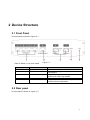
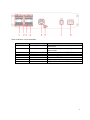
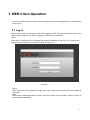
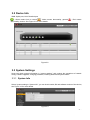
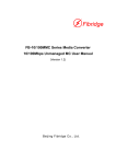
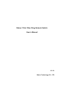
Dahua 7-Port Fiber Ring Network Switch User’s Manual V1.0.0 Dahua Technology CO., LTD Important Safeguards and Warnings Please read the following safeguards and warnings carefully before using the product in order to avoid damages and losses. Note: Do not expose the device to lampblack, steam or dust. Otherwise it may cause fire or electric shock. Do not place the device at position exposed to sunlight or in high temperature. Temperature rising in device may cause fire. Do not expose the device to humid environment. Otherwise it may cause fire. The device must be installed on solid and flat surface in order to guarantee safety under load and earthquake. Otherwise, it may cause device to fall off or turnover. Do not place the device on carpet or quilt. Do not block air vent of the device or ventilation around the device. Otherwise, temperature in device will rise and may cause fire. Do not place any object on the device. Do not disassemble the device without professional instruction. Warning: Please use battery properly to avoid fire, explosion and other dangers. Please replace used battery with battery of the same type. Do not use power line other than the one specified. Please use it properly. Otherwise, it may cause fire or electric shock. Special Announcement: This manual is for reference only. All the designs and software here are subject to change without prior written notice. All trademarks and registered trademarks are the properties of their respective owners. If there is any uncertainty or controversy, please refer to the final explanation of us. Please visit our website for more information. We are not liable for any problems caused by unauthorized modification or attempted repair. Table of Contents 1 Product Overview ............................................................................................. - 1 1.1 Features............................................................................................................................ - 1 1.2 Typical Application ............................................................................................................ - 2 1.2.1 General Mode............................................................................................................ - 2 1.2.2 Ring Network Mode ................................................................................................... - 2 - 2 Device Structure ............................................................................................... - 3 2.1 2.2 3 Front Panel ....................................................................................................................... - 3 Rear panel ........................................................................................................................ - 3 - WEB Client Operation ...................................................................................... - 5 3.1 Log in ................................................................................................................................ - 5 3.2 Device Info ........................................................................................................................ - 6 3.3 System Settings ................................................................................................................ - 6 3.3.1 System Info ............................................................................................................... - 6 3.3.2 Network Config .......................................................................................................... - 7 3.3.3 Software Upgrade ..................................................................................................... - 7 3.3.4 Change Password ..................................................................................................... - 8 3.3.5 Restore Default ......................................................................................................... - 8 3.3.6 System Reboot .......................................................................................................... - 8 3.4 Device Management......................................................................................................... - 9 3.4.1 Ring Config ................................................................................................................ - 9 3.4.2 Serial Config .............................................................................................................. - 9 3.4.3 802.1Q VLAN Config ............................................................................................... - 10 3.4.4 MAC Security .......................................................................................................... - 11 3.5 Port management ........................................................................................................... - 12 3.5.1 Port Config .............................................................................................................. - 12 3.5.2 Port Mirroring Config ............................................................................................... - 12 3.5.3 Port Speed Limit ...................................................................................................... - 12 - 4 FAQ .................................................................................................................. - 14 - Appendix 1 Toxic or Hazardous Materials or Elements .................................... - 15 - 1 Product Overview 7-port fiber ring network switch is a 2-layer switch which supports network management and ring network redundancy function, providing 4 10M/100M self-adaptive Ethernet ports, 1 10M/100M/1000M self-adaptive Ethernet port and 2 Gbps fiber ports, and conducting long-distance transmission by single module dual fiber, which can be widely applied in safe city, highway and other places. 1.1 Features The product is a 2-layer switch. Support 2 Gbps SFP (Small Form-factor Pluggables) fiber ports, two fiber ports can be made up as a fiber ring network. Support 4 10M/100M self-adaptive RJ45 ports. Support 1 10M/100M/1000M self-adaptive RJ45 port. Support 4 RS485 ports and 1 RS232 port. Support 4 on-off inputs and 2 on-off outputs. Support 1 CONSOLE port. Conform IEEE802.3, IEEE802.3u, IEEE802.3ab/z and IEEE802.3X standards All ports automatically adapt MDI/MDIX mode. MAC automatic learning and aging, MAC address list’s capacity is up to 8K. Adopt metal case, brand-new appearance and structure. IEEE802.3X full dual flow control and Backpressure half dual flow control. Support DC12V, DC24V, and AC24V power supply. Support SNMP (Simple Network Management Protocol)protocol. Support STP(Spanning Tree Protocol)protocol. Working temperature: ﹣40℃~﹢75℃. Indicator displays data transmission status and power status - 1 - 1.2 Typical Application 1.2.1 General Mode See Figure 1-1 for the general mode. Figure 1-1 1.2.2 Ring Network Mode After the ring network mode is enabled, it can be used to stop generating broadcast storm on the loop, and it can rapidly switch data transmission link during link failure, which can improve reliability and ensure the normal transmission of business data. See Figure 1-2 for more details. Figure 1-2 - 2 - 2 Device Structure 2.1 Front Panel The front panel is shown in Figure 2- 1. Figure 2- 1 Refer to Sheet 2-1 for more details. SN 1 2 Name RJ45 Port RJ45 Port 3 Fiber Port 4 5 Fiber Port Indicator Reset Button Function Ethernet port, support 10/100M self-adaptive Ethernet port, support 10/100/1000M self-adaptive Gbps SFP fiber port, two fiber ports can be made up as a fiber ring network. Fiber port status indicator Long press the button for reset operation, and recover default configuration. 2.2 Rear panel The rear panel is shown in Figure 2- 2. - 3 - Figure 2- 2 Refer to Sheet 2-2 for more details. SN 1 2 3 4 5 6 7 8 Name Alarm Input Port Function Connect alarm input device, support 4 channel alarm input. Alarm Output Port Connect alarm output device, support 2 channel alarm output. RS485 Port Connect external device of RS485 port. RS232 Port Connect external device of RS232 port. CONSOLE Serial Port Device debugging port. GND Screw GND Power Port Support DC 12V power supply Power Port Support DC 24V or AC 24V power supply. Sheet 2-2 - 4 - 3 WEB Client Operation Users can conduct system setting, device management and port management by connecting the device to PC. 3.1 Log in Make sure the device is connected to PC before logging in Web, and make the PC and device in the same network segment. The steps of logging in WEB client are as follows: Step 1 Enter device IP address in the IE address bar (default IP address is: 192.168.1.110), press Enter, and the system displays the interface as shown in Figure 3-1. Figure 3-1 Step 2 Enter “User name” and “password”, single click “Login”, the system will enter the main interface of Web client. Note: Device factory default password is empty; users only need to enter username “admin”, and log in without entering password. - 5 - 3.2 Device Info WAN: Uplink port; LAN: Downlink port :Green means link is normal; :Yellow means abnormality, general; abnormality, serious. See Figure 3-2 for more details. :Red means Figure 3-2 3.3 System Settings Users can check system information in “system settings”, and conduct the operations of network config, software upgrade, changing password, restoring default and system reboot. 3.3.1 System Info Select “system settings > System info”, you can check model, SN and software version of the device, see Figure 3-3 for more details. Figure 3-3 - 6 - 3.3.2 Network Config DHCP Mode After you select “DHCP” mode, you only need to configure DNS server, the device will auto acquire IP address. Static Mode You can configure device IP address, subnet mask and default gateway through network config. Step 1 Select “System Settings > Network Config”, the system will display the interface which is shown in Figure 3-4 below. Figure 3-4 Step 2 Configure “IP address”, “Subnet mask”, “Default gateway” and “DNS server”. Step 3 Click “Save” and complete configuration. 3.3.3 Software Upgrade You can upgrade software to the latest version by software upgrade. Step 1 Select “System Settings > Software Upgrade”, the system will display the interface which is shown in Figure 3-5 below. Figure 3-5 - 7 - 3.3.4 Change Password There is no default password when the device is delivered out of factory. Therefore, you don’t need to enter original password when changing password. See Figure 3-6 for more details. Figure 3-6 3.3.5 Restore Default After you click “Restore Default Config”, the system will restore factory default configuration, please operate carefully. Note: After clicking “Restore Default Config”, IP address won’t restore default configuration. See Figure 3-7 for more details. Figure 3-7 3.3.6 System Reboot You can conduct remote reboot operation to the device by “System Reboot”. See Figure 3-8 for more details. - 8 - Figure 3-8 3.4 Device Management You can make ring config, serial config, 802.1Q VLAN config and PORT VLAN config through device management. 3.4.1 Ring Config Redundancy ring function can be realized by ring config. Step 1 Connect cable according to the ring mode which is shown in Figure 3-9. Step 2 Log in WEB interface, select “System settings > Device Management > Ring Config”, check “Enable”. Step 3 Click “Save”. Figure 3-9 3.4.2 Serial Config Serial port needs to be configured when it is connected to external device. See Sheet 3-1 for more details about serial parameter. - 9 - Parameter Description Serial Index Serial number, 1~4 respectively match RS485 ports of A1B1~A4B4. Serial Enable Control serial enable. Serial Type Only RS485 optional. Serial Mode Currently only support transparant serial. Protocol Type Select prtocol type, including TCP and UDP. IP Address Data transmission destination IP address. IP Port Data transmision destination IP port. Baud Rate Data Bit Serial control information, keep consistent with external device. Stop Bit Parity Bit Sheet 3-1 See Figure 3-10 for more details about serial config. Figure 3-10 3.4.3 802.1Q VLAN Config IEEE802.1Q is a protocol with VLAN identifying information for data frame which is authenticated by IEEE, which is also called “Tagging VLAN”. It can recognize max 4096 VLAN, the current configurable range is 1~4094. - 10 - Default VLAN ID number When the port receives a package without VLAN Tag, the system will add default VLAN ID of the port, and forward the package to a port with default VLAN ID. VLAN ID number which is allowed to pass It means the VLAN which is allowed to pass by this port, and the range is 1~4094. When the port sends package, and if the VLAN ID of this package is the same as the default VLAN ID, then the system will remove the VLAN Tag of the package, and send this package. Step 1 Select “Device Management > 802.1Q VLAN Config”, which is shown in Figure 3-11. Step 2 Check “Enable 802.1QVLAN Config”, which means enabled. Step 3 Set “default VLAN ID”, under the situation of default, the default VLAN ID of port is 1. Step 4 Set Allow VLAN ID. Step 5 Click “Save”, and complete the config. Figure 3-11 3.4.4 MAC Security MAC address flooding is a kind of attack which is produced by illegal users using tools, this kind of attack will result in flow sending to all the ports with VLAN of all the switches by a way of flood, which will cause overload, slow network, and packet loss even breakdown for the switch. Limit the max MAC quantity studied by single port (set 0 means no limit, max is 255), which effectively solves the problem of MAC address flooding. See Figure 3-12 for more details. Figure 3-12 - 11 - 3.5 Port management You can conduct port config, port mirroring config, port statistics and port speed limit through port management. 3.5.1 Port Config You can set priority for each port by port config. The port with high-level priority can be processed first when flow congestion is generated among several ports. “Enable Flow Control” means sending flow control message to data source port and adjusting network transmission rate when network congestion is on the way. See Figure 3-13 for more details. Figure 3-13 3.5.2 Port Mirroring Config You can mirror the data of one port to another port by port mirroring, which can help the repair staff to locate problems. See Figure 3-14 for more details. Figure 3-14 3.5.3 Port Speed Limit You can limit the speed of each port by port speed limit. See Figure 3-15 for more details. - 12 - Figure 3-15 - 13 - 4 FAQ Problem or Phenomenon Device power malfunction Link/Act(Fiber port indicator)not working Network operation normal, individual device unable to work normally. No network Switch indicator flicker frequency is very high, it can work normally for a short time when power on again after power off, but it soon restore to its original status. Possible Reasons External power supply unstable or power cable aging cause power damage. Optical module, fiber select unreasonable; fiber connection problem. Solutions Port network cable loose or the port is polluted. Check port network cable connection, keep the operation place clean. The system software version And the device are not matched. Network loop Generally because both ends Of one physical network cable Are connected to the same Network device. Network virus attack Due to virus attack, it brings network bandwidth loss and network congestion. Replace power Select module reasonably, check if fiber connection is correct, or fiber insert reversely. Upgrade system software. Check if it is loop, if yes, please cut off corresponding link or enable ring network function Check it receives network virus attack, please install firewall. - 14 - Appendix 1 Toxic or Hazardous Materials or Elements Component Name Toxic or Hazardous Materials or Elements Pb Hg Cd Cr VI PBB PBDE Circuit Board Component ○ ○ ○ ○ ○ ○ Device Case ○ ○ ○ ○ ○ ○ Wire and Cable ○ ○ ○ ○ ○ ○ Packing Components ○ ○ ○ ○ ○ ○ Accessories ○ ○ ○ ○ ○ ○ O: Indicates that the concentration of the hazardous substance in all homogeneous materials in the parts is below the relevant threshold of the SJ/T11363-2006 standard. X: Indicates that the concentration of the hazardous substance of at least one of all homogeneous materials in the parts is above the relevant threshold of the SJ/T11363-2006 standard. During the environmental-friendly use period (EFUP) period, the toxic or hazardous substance or elements contained in products will not leak or mutate so that the use of these (substances or elements) will not result in any severe environmental pollution, any bodily injury or damage to any assets. The consumer is not authorized to process such kind of substances or elements, please return to the corresponding local authorities to process according to your local government statutes - 15 - Note This user’s manual is for reference only. Slight difference may be found in user interface. All the designs and software here are subject to change without prior written notice. All trademarks and registered trademarks are the properties of their respective owners. If there is any uncertainty or controversy, please refer to the final explanation of us. Please visit our website for more information. Dahua Technology CO., LTD. Address:No.1199 Bin’an Road, Binjiang District, Hangzhou, PRC. Postcode: 310053 Tel: +86-571-87688883 Fax: +86-571-87688815 Email:[email protected] Website: www.dahuatech.com - 16 -