1
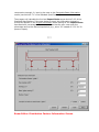
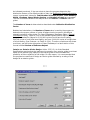
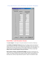
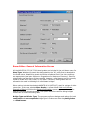
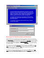
AISIBEAM User's Manual (Version 3.0)
Shabin Taavoni, Ph.D., PE,
title
Structural Software Inc.
location
John C. Huang Ph.D., PE,
Principal
CHC Engineering, LLC
Herndon, VA
Scope of Software
The software is based on the Strength Design Method (Load Factor Design) of the
AASHTO Standard Specifications for Highway Bridges, 16th Edition, 1996, including
the 1997, 1998, and1999 Interim Specifications, referred to herein as the Standard
Specifications. The software uses group I LFD load combinations. The Software will
perform a line-girder analysis for simple-span girder and rolled beam bridges. The
following items can be customized by the user:
•
•
•
•
•
•
•
•
Welded plate girders with unstiffened webs
Rolled beams with optional welded cover plates
Composite and non-composite stringers
Normal weight and lightweight concrete deck material
AASHTO strength, deflection, fatigue and constructibility criteria
HS (MS) type truck load or special loading with up to 15 axle loads
Up to 25 alternate sol utions for each design
Supporting design calculations
•
•
•
•
Customary U.S. units
SI (metric units)
Alternate fatigue load of HS (MS) configuration
Operating and Inventory rating
In the design mode, the software will iterate between a range of user-specified
minimum and maximum cross section dimensions to find a minimum weight solution.
In the rating mode, the user can input the exact cross section properties and the
Software will then solve for both an Inventory and Operating Rating.
Software Installation
The Software runs under Microsoft Windows 95, 98, 2000 and the latest versions of
Windows NT. A minimum 10 MB hard -disk space is recommended, along with 16 MB
memory.
For efficient operation, install and run the Software from the hard drive and use the
CD for viewing and printing the plans. It is recommended to install the Software in
the directory of default Drive: \Programs\AisiBeam (for example
C:\Programs\AisiBeam). Before installing Version 3.0 of the program:
•
•
•
Delete any previous versions of the software (AisiBeam.exe) from the hard
drive (recommended but optional).
Close any applications that may be running prior to installation.
Follow the basic Windows instructions for loading software.
After installation, copy any previously generated input files to be used with the
Version 3.0, to the AISIBEAM directory where the Version 3.0 is installed. Always
keep the input and output files in the directory of AISIBEAM Version 3.0. If you must
save input files in a file folder other than the AISIBEAM folder, cop y the following
three text files (AISC.txt, AISC1.txt, and MAISC.txt) into the same folder as the
input file. For additional support contact your system administrator. If difficulties
persist have your system administrator contact AISI at [email protected] .
***
Main Menu Screen
The Main Menu screen contains the following four elements: File (for file operations),
Run (for executing a file design or rating), Graphs (for displaying moment, shear,
deflection diagrams and moment, shear, deflection influence lines), Standard
Drawings (for viewing and printing of standard drawings) and Help. The File menu
contains the following seven menu items:
New Project, Open Existing Project, View Project Output, Print, Save As,
Remove File and Exit.
To develop a new input file for a design or rating, select File from the Main Menu
screen, then New Project from the pull-down menu. Beam Editor, Project
Information screen will appear. Select the appropriate options and enter the input
data in the input text boxes. When finished, click on the Next Button a new screen
will appear. Continue entering the data in the input boxes for each screen until you
get to the last screen (Save Input File screen). Select Save from the Save Input File
(Save Menu) screen. A Save as dialog screen will appear, enter the input file name
and save the file. Do not use an extension in naming the input file, such as bridge.1.
Instead, use bridge1 or equivalent.
A new input file can also be developed by editing an existing input file. To edit an
existing file, select File from the Main Menu screen, then Open Existing Project
from the pull-down menu. Open dialog screen appears, type in or select the name of
the file to be edited and click on the Open Button. Beam Editor, Project Information
screen will appear. The content of input file would be loaded in the Beam Editor.
Keep or change the input data and options as needed. When finished, click on the
Next Button a new screen will appear. Continue entering data in each screen until
you get to the last screen (Save Input File screen). Select Save from the Save Input
File (Save Menu) screen. A Save as dialog screen will appear, to preserve the original
file, enter a new file name; to write over the original file, use the same file name.
When creating or editing a file, the user may use the cursor or the Tab key to move
between data boxes and buttons. The units, if any, for the input are displayed on the
screen near each box. The user may return to any box within a screen to change
data. When all entries are made, click on Next Button to proceed to the next
screen, Back Button to go back to the previous screen, Cancel Button to return to
the Main Menu screen, or Restart Button to return to the Project Information
screen. These buttons appear at the bottom of most screens.
Remove File and Save As are file management menu items. Remove File will
allow the user to view the computer directories to select and delete a file. Save As
will allow the user to rename a file stored on the hard drive.
The Print menu item prints out any designated output file (.out) or options file
(.opt). The output file for the latest run is the default file for printing.
The View Project Output allows the user to view the output file (.out), options file
(.opt), or the Options.doc file. The Options.doc shows the current design options of
the latest run on the screen. The View Project Output defaults to the files
containing the results from the latest run.
To avoid running multiple versions of the program simultaneously, it is required that
you exit the software using the Exit menu item only.
After saving an input file, the program can then be executed by selecting Run and
then Start menu item in sequence. By default, the program will select the last
created or edited file. For naming the output (. out) and option (. opt) files, the
program will default to the input file name and add the appropriate extension (. out)
or (. opt).
The Graphs menu allows the user to view the moment, shear, deflection diagrams
and moment, shear, deflection influence lines for the last run on the screen. These
diagrams are not available for printing.
The Help menu contains the following menu items, Contents, How to Design or
Rate a Bridge, Help on Web, Order Your Copy and About. The Contents menu
item contains the software manual on line. How to Design or Rate a Bridge menu
item serves as an executive summary of the manual on line for quick reference.
Help on Web menu item will connect the user to AISI web site for updated help or
other information. Order Your Copy menu item is for filling and printing the
ordering form. About menu item contains information about version number and
software author.
***
Beam Editor: Project Information Screen
The Project Description area is provided for optional descriptive bridge
information. This information will be included on the first page of the output file for
the purpose of identifying the output by other than the file name.
The program will accept customary U.S. units or SI (metric) units as a System of
Measurement. Units for specific measurements, if any, will be indicated near the
input boxes. Output is generated in the appropriate units of the selected system of
measurement. Due to the differences in rounding and transformation of scalars and
limits, U.S. unit and SI unit designs will not be exact conversions. See Appendix E of
the Standard Specifications for the SI equivalents of the customary U.S. unit
measurements and for the equations in both systems of measurement that are used
in this program.
The user has the option to input the effective width, cross bracing, modular ratio N,
distribution factors and Impact factor or allow the program to compute and input
these values automatically. If the user elects to input distribution factors, prompts
will appear on the Load Information screen for the user to input the moment, shear
and deflection distribution factors. If the user elects to input effective width, prompts
will appear on the Composite Beam Information screen for the user to input the
effective width of slab.
The Distribution Factors and Effective Width data will be determined by the
program in accordance with the Standard Specifications as specified in Articles 3.23
or 10.38.3, respectively, unless input by the user.
The Shear Distribution Factor applies only to wheel loads located at the support
end of girders. Reduction for multiple lanes is only used for the deflection factor, but
not for other distribution factors. For wheel loads that are located along the span
length, the Moment Distribution Factor is applied.
The Deflection Distribution Factor (DDF) may be computed considering all girders
acting together and having equal deflection, as permitted in Article 10.6.4. The
program calculates this factor as follows:
DDF = [(Lanes) x (2 Wheels per axle) x (Multiple Lane Reduction)]/ (Number of
Girders)
Where Lanes is determined by dividing the clear roadway width
excluding the shoulders, if any, by 12 ft (3.60 m) and rounding down
to a whole number of lanes. Roadway widths of 20 ft to 24 ft (6.00 m
to 7.20 m) shall be considered to have 2 Lanes. Multiple Lane
Reduction is defined in Article 3.12 of the Standard Specifications as
1.00 for less than three loaded lanes, 0.90 for three loaded lanes, and
0.75 for more than three loaded lanes.
Cross Bracing. Article 10.20.1 of the Standard Specifications states that the
maximum cross bracing spacing on straight stringer bridges shall not exceed 25-ft
(7.60 m). The Software will default to have the cross bracing placed along the span
at the fewest number of equal intervals to satisfy this requirement. Otherwise, the
user will be prompted for cross bracing locations on the Bracing Information screen.
The Brace Distances supplied by the user on this screen may exceed the 25 ft limit.
The first and last cross bracings on this screen represent the end diaphragms of the
bridge and therefore need to be placed at each end of the stringer.
The Modular Ratio, N, is the ratio of the modulus of elasticity of steel to that of
concrete, Es/Ec. The user may either input the appropriate value given in Article
10.38.1.3 of the Standard Specifications for normal weight concrete, or else the user
may elect to have the program compute the modular ratio. The program assumes a
modulus of elasticity for steel of 29,000,000 psi (200,000 MPa) and determines a
modulus of elasticity for concrete by using the concrete unit weight, wc, and
compressive strength, fc, input by the user on the Composite Beam Information
screen (see Article 8.7.1 in the Standard Specifications).
The program will calculate the live-load Impact Factor as per Article 3.8.2 of the
Standard Specifications. If the user elects to supply this information instead, a
prompt will appear on the Project Information screen asking for the Impact Factor
expressed as a percentage of the live load. Note that the user must enter the
percentage and not the decimal equivalent (e.g., enter '30' instead of '0.30' for 30
percent impact).
***
Beam Editor: Distribution Factors Information Screen
As indicated previously, if the user elects to have the program determine the
distribution factors or the effective width of slab, the Distribution Factors Information
screen is generated. Values for Total Number of Beams/Girders, Clear Roadway
Width, Overhang, Beam/Girder Spacing, and Number of Lanes are requested.
The user must also indicate if the analysis is for an Interior or Exterior beam or
girder.
The Number of Lanes is determined as described under Deflection Distribution
Factor.
Besides load calculations, the Number of Lanes value is used by the program to
determine the proper number of cycles of fatigue load to be used in the fatigue
strength evaluation of the girder. For Case I Roadways (See Beam Editor: General
Information screen), Table 10.3.2A of the Standard Specifications requires that the
design be checked for fatigue for 2,000,000 cycles of multi-lane truck loading,
500,000 cycles of multi-lane lane loading, and over 2,000,000 cycles of a single lane
of truck loading. (See Footnote c to Table 10.3.2A). To ensure compliance with these
provisions, see the further discussion of Case I Roadways in a later section of this
manual entitled Review of Software Output.
Interior vs. Exterior Girder Design. Article 3.23.2.3.1.4 of the Standard
Specifications requires that the load carrying capacity of an exterior girder be at least
equal to the load carrying capacity of an interior girder to accommodate the
possibility of future widening of the bridge. For this reason, it is recommended that
the program be used first to design an interior girder followed by a rating of that
design as an exterior girder.
***
If Live Load Vehicle is not an HS Vehicle, input vehicle information:
Beam Editor: Load Information Screens
The Span Length is the length of the girder between the centerline of bearings.
The Number of Segments in Span indicates where design checks and changes in
section properties are made. In the Design Mode, regardless of the user input, the
program assumes ten equal sections along the span length for both plate girders and
rolled beams, and 50 equal sections for cover-plated rolled beams. In the Rating
Mode, the user may specify any multiple of 10 sections (i.e. 10, 20, 30, etc.) for
design checks or section changes for all types of girders.
Dead Load Per Stringer (Excluding Self-Weight) indicates the dead load to be
carried by the non-composite section of the stringer excluding the self-weight of the
stringer. The loading consists of the weight of the deck, stay-in-place deck forms,
deck haunches, and any weight allowance (assume 3 psf) for miscellaneous steel
details such as cross bracings. Refine the final design as necessary to account for the
actual weight of the steel. Note that the weight of steel stringers is calculated by the
program. In order to get a comparable design with previous AISIBEAM versions;
adjust the old input files to account for the dead load of the steel.
Superimposed Dead Load per Stringer indicates the dead load to be carried by
the long-term composite (3N) bridge section, including parapets and any future
wearing surface added to the bridge after the casting of the deck. Article
3.23.2.3.1.1 of the Standard Specifications permits curbs, railings and the future
wearing surface to be distributed equally to all girders.
Fatigue Vehicle. Adequate fatigue life of steel bridges is ensured by proportioning
members so that the calculated load -induced stress range at fatigue sensitive details
does not exceed the allowable fatigue stress range for that detail. Distortion -induced
fatigue is controlled by proper detailing (See plans).
Fatigue design in the Standard Specifications has been developed for an HS20
(MS18) truck load. The use of a heavier or lighter truck load [HS25 (MS22.5) or
HS15 (MS13.5)] is only permissible for strength design; the use of these vehicles for
fatigue design would yield results that are inconsistent with the calibration used to
develop the S-N curves in the Specifications. Hence, an HS20 (MS 18) truck is
specified as the default Fatigue Vehicle in this program and should be used
regardless of the design live load vehicle that is specified. The user, however, does
have the option to enter a different HS (MS) fatigue vehicle.
Live Load Vehicle. The software defaults to an HS20 (MS18) live load. If the design
Live Load Vehicle is not of an HS (MS) configuration, the user will be prompted to
provide a live-load configuration using the Vehicle Information screen. This screen
will accept up to 15 wheel loads at user-input spacings to model the desired design
vehicle.
***
Beam Editor: General Information Screen
All the AASHTO M 270 (M 270M) steel grades are included in the pull-down menu for
Steel Type. Weathering steels are designated by the "W" suffix that is attached to
the Grade value. Weathering steels should be considered first if the site conditions
are appropriate (see later section on Suggestions for Maximum Economy). Steel for
plate girders can be of any of these grades, however, rolled beams are not currently
made of Grade HPS 70W, I00W, or 100 steel. Therefore, these grades are not
allowed to be used in the design of rolled beam bridges.
Other options include the obsolete AASHTO M 94 (ASTM A7) steel for ratings of older
structures. If the user selects Other Grades, a screen titled Yield and Ultimate
Strength of Steel will follow the General Information screen to prompt the user for
data on yield and ultimate strength. This option would be used for rating bridges
made from an unknown steel grade.
Bridge Type and Girder Type. The program performs designs and ratings for both
composite and non-composite bridge types. Girders can either be plate girders
or rolled beams.
The Live Load Deflection Constraint defaults to 1 /800 of the span length, which is
the recommended value in Article 10.6.2 of the Standard Specifications. The user
can modify the value of this constraint.
The pull-down menu for Fatigue Road Case Number includes three choices: Case
I, Case II, or Case Ill. Freeways, expressways, major highways and streets are
defined in Table 10.3.2A of the Standard Specifications as Case I roadways if they
have an Average Daily Truck Traffic (ADTT) of 2,500 or more. These same roads are
defined as Case II roadways if they have an ADTT of less than 2,500. All other
highways and streets not included in the Case I or Case II definition are classified as
Case Ill roadways.
Calculation Type. The user may elect to design a new bridge or rate an existing
one. Designs are generated using the Load Factor Method of the Standard
Specifications. Ratings are done in accordance with the AASHTO Manual for Condition
Evaluation of Bridges, 1994.
Check Constructibility. This item concerns the resistance to lateral-torsional
buckling of the compression flange of the girder under its own self-weight and the
weight of the concrete deck before it hardens. Select Yes to have the program check
lateral-torsional buckling between brace points according to Article 10.48.4.1 of the
Standard Specifications. Currently, the program will only check constructibility when
in Design Mode. To check constructibility for an existing design in Rating Mode,
select the Check Constructibility option in design mode and restrict the design
parameters such that the pre-designed girder is selected. The program does not
check for stability during handling, shipping and/or erecting.
Print All or Part of the Output File. The output file generated after each run has a
file extension of out. The extension (out) can be modified by the user. If only part of
the output is needed, the Print Options screen will prompt the user to choose the
sections of the file that need to be printed.
The default setting for this screen is to include all sections of the file. The user can
de-select any section that is not needed. The Load Rating Information (Section VI) is
only generated when the program is executed in the Rating Mode.
Note that the options file has the same name as the output file only with a file
extension of opt. See the following discussion under Main Menu screen for additional
information on the options file. Both the output file and the options file are printed
using the Print command on the Main Menu screen.
***
Beam Editor: Composite Beam Information Screen
When a composite girder is being considered, the user will have to supply
information about the concrete and shear studs on this screen. This is also the
screen where the user will have to supply the Modular Ratio, N, or the Effective
Width of Slab, or both, if they are not determined automatically by the program
(See the previous discussion on the Project Information screen for more
information). The 28-day Concrete Strength, fc must be entered by the user.
Slab Thickness is the structural slab thickness used for design. Do not include the
thickness of either the integral wearing surface or the future wearing surface in this
value.
The Haunch Thickness is defined as the distance from the top of the girder web to
the bottom of the concrete deck slab. A minimum of 2 in. (50 mm) is usually
specified.
In SI units, the Unit Weight of Concrete indicates the mass of the concrete in
kilograms per cubic meter. A customary U.S. unit normal weight concrete of 150 pcf
has an equivalent SI unit concrete mass of 2400 kg/m3.
The Number of Studs Per Row refers to the number of shear studs placed in a row
transversely across the flange. Shear studs are not currently produced in hard SI
(metric) units. The following lists the currently available customary U.S. shear Stud
Diameters and the accepted equivalent soft-converted SI values: 1/2 in. (12.7
mm); 5/8 in. (15.9 mm); 3/4 in. (19 mm); 7/8 in. (22.1 mm).
***
Beam Editor: Rolled Beam Design Information Screen
Maximum Total Depth of Beam and Minimum Total Depth of Beam refers to
the actual rolled beam depth, plus cover plate thickness if cover plates are provided.
The properties of the rolled beams that may be selected by the user are stored in the
Software. The properties of the metric rolled beams correspond to the properties
given in the AISC publication 4. If the user wants to utilize a beam in which the actual
depth exceeds the nominal depth, but the user only specifies the nominal depth, the
program may not converge to a solution. To avoid this situation, the user can specify
a wide range of total depth for the beam, such as 12 in. (300 mm) minimum to 50
in. (1270 mm) maximum, without a loss in design efficiency.
Ratio of Cover Plate Thickness/Flange Thickness. The program restricts the
user to single cover plate designs. Article 10.13.3 of the Standard Specifications
states that the maximum thickness of a single cover plate shall not be greater than 2
times the thickness of the flange to which the cover plate is attached. If a cover
plate is used, the user may want to make several runs, exploring various ratios of
cover plate thickness to flange thickness in order to generate a cost-effective
solution.
***
Beam Editor: Rolled Beam Rating Information Screen
Type of Rolled Beam. Enter the Size (Nominal Depth) of the rolled beam in the
first input box and Nominal Weight in the second input box on the same row.
Length of Cover Plate, Width of Cover Plate and Thickness of Cover Plate. If
the rolled beam has symmetrical cover plate, enter the length, width and thickness
of it in the corresponding input boxes. For beams without cover plate leave these
input boxes empty.
***
Beam Editor: Plate Girder Rating Information Screen
Distance from Left Support, this is the distance from the end of each segment to
the left support. If the thickness of top flange, bottom flange and or web section
varies along the beam, at each section variation a new segment must be defined. For
a girder with a constant section a minimum of two segments must be defined
(segments 0,1). The distance from left support for the last segment must be equal to
the span length.
Top Flange Width, Top Flange Thickness, Web Depth, Web Thickness,
Bottom Flange Width and Bottom Flange Thickness, these values must be
entered in the corresponding input boxes for each segment. For segment 0 the
section properties for section to the right of first support must be entered. For all
other segments the section properties to the left of the segment's end must be
entered. For this reason the section properties of segments 0 and 1 are identical for
constant depth girders.
***
Save Input File: Save Menu Screen and Run Screen
After completing all the appropriate screens for creating or editing of an input file,
the Save Input File screen will appear. Select Save from the menu to save the data
file, which will then automatically return the user to the Main Menu screen to execute
a run. Select Restart to return to the Project Information screen to review or edit
the input file data. Select Cancel to return to the Main Menu screen without saving
the input file data.
After saving the input data, Main Menu screen will appear, select Run on the Main
Menu screen. Then, select Start. The Run screen will echo the file name and the
default output file name. The user can rename the output file at this point if
required. Select OK to execute the program.
To review the program output file (.out) on the screen, select File from the Main
Menu screen then View Project Output menu item. The View File screen will
appear. After each run the name of the last output file will be inserted in the upper
right corner input box of the View File screen. Click on the OK Button to review this
output file. The output file contains the least weight design. The user can also use
the pull-down menu to view other valid designs in the file
C:\Programs\AisiBeam\Options.doc (provided the software is installed in the
default directory of C:\Programs\AisiBeam). This temporary file is generated for
the latest design and includes a summary of up to 25 least-weight solutions listed in
order of increasing weight. This feature may be quite useful in developing alternate
designs, or for modifying the least-weight solution to make it more practical for a
given situation. The user can also review any output or Options.doc files, by entering
the file name in the upper corner input box of the View File screen and clicking on
OK Button.
Moment, shear, and deflection diagrams, and influence lines are generated after
each run. This information can be accessed through the Graphs menu on the Main
Menu screen and can only be reviewed on the screen and is not stored in a
permanent output file and it cannot be printed.
***