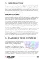
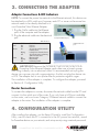
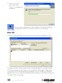
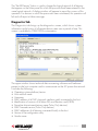
1
PowerLine
Turbo
Ethernet
Adapter
User
Manual
Model 502641
INT-502641-UM-0706-05
Table of contents
section
page
1. Introduction........................................................................3
2. Planning Your PowerLine Network..................................3
3. Connecting the Adapter.....................................................4
Adapter Connections & LED Indicators..........................................4
Connecting to a Router..............................................................4
4. Configuration Utility..........................................................4
Utility Installation & Access.........................................................................5
Main Tab ..............................................................................6
Privacy Tab.............................................................................8
Diagnostics Tab.......................................................................9
About Tab.............................................................................10
5. Troubleshooting............................................................... 11
6. Specifications................................................................... 11
How to Use this Manual
This user manual has been designed to make understanding networking with
the INTELLINET NETWORK SOLUTIONS™ PowerLine Turbo Ethernet Adapter
easier than ever. Look for the following items when reading this manual:
This check mark means there is a note of interest about something you
should pay special attention to while using the device.
This exclamation point means there is a caution or warning about
something that could damage your property or the bridge.
2
Table of Contents
1. INTRODUCTION
Congratulations on your purchase of the INTELLINET NETWORK SOLUTIONS
PowerLine Turbo Ethernet Adapter, Model 502641. The adapter will allow you
to network better than ever by letting you turn the existing AC power lines in your
home or office into a high-speed network. Now you don’t have to drill through
the walls or climb through the attic or cellar to install network cables. Just use the
wires that already run through the building.
What Does All This Mean?
Networks are useful tools for sharing computer resources. You can access one
printer from different computers and access data located on another computer’s
hard drive. Networks are even used for playing multiplayer video games. So
networks are not only useful in homes and offices, they can also be fun!
The PowerLine Turbo Ethernet Adapter interfaces Ethernet devices to the
HomePlug network standard. Just plug the adapter into the wall, connect your
Ethernet-equipped device to the adapter using the included network cable,
and you’ve turned your whole house into a network infrastructure. Attach more
computers to the network simply by plugging them into the wall anywhere in
the house and using more adapters.
Once your computers are connected to the network, they can share resources such
as printers and storage space, plus all kinds of files: music, digital pictures and
documents. With up to 85 Mbps data rates, you can play head-to-head
network computer games, too. And if you use a PowerLine Turbo Ethernet Adapter
to interface broadband routers from your cable or DSL Internet connection to your
network, you’ll be able to get to the Internet from any computer in the house.
2. planning your network
With PowerLine devices, a computer network
can be created using home power lines. The
adapter connects an Ethernet-enabled
computer to an AC power line network.
The adapter is also ideal for any user who
already has a router and wants to share highspeed Internet access across the AC power line
network. Connect the adapter to the router after you have
configured the adapter using the configuration utility. Connect a straight-through
Category 5 Ethernet network cable to the uplink port of the router, or connect
a crossover Category 5 Ethernet network cable to a LAN port on the router.
INTRODUCTION / PLANNING YOUR NETWORK
3
3. connecting the adapter
Adapter Connections & LED Indicators
NOTE: To connect the power line network to the Ethernet network, this device can
be attached to a LAN switch port; however, each PC or server on the power line
network needs to be directly attached to its
own PowerLine Turbo Ethernet Adapter.
1. Plug the Cat5ecable into the Ethernet
ports of the computer and the adapter.
2. Plug the electrical cable into the electrical
port.
Computer Ethernet port
LED indicators
LED
STATUS
Power
On
Off
Link/Act
On
Blinking
Off
Ethernet
On
Blinking
Off
DESCRIPTION
Power on
Power off
AC power line port detects another PowerLine device
Looking for more PowerLine devices
AC power line port is not detecting another PowerLine device
Ethernet port link
Ethernet activity
No Ethernet port link
Adapter Ethernet
port
IMPORTANT: Because the INTELLINET NETWORK SOLUTIONS
PowerLine Turbo Ethernet Adapter sends data over a home’s power
lines, plug it directly into an electrical outlet. It’s recommended not to plug the
device into a power strip with surge protection. And do not plug the device into
a UPS: The adapter has its own power filter for protection against surges.
The installation of the adapter is complete. To configure the adapter, proceed
to Section 4: Configuration Utility.
Router Connections
To connect the adapter to a router, disconnect the network cable from the PC and
connect it to the uplink port of the router. If you only have a LAN port available
on the router, use a crossover Category 5 Ethernet network cable to connect the
adapter to the router. The installation of the adapter is complete.
4. configuration utility
After installing the adapter, run the Setup Wizard to install the Configuration
Utility, used to check the PC’s connection to the AC power line network, search
for PowerLine devices on your network, and set up security using a network password.
4
CONNECTING THE ADAPTER / CONFIGURATION UTILITY
NOTE: If you want the devices on your PowerLine network to share
high-speed Internet access, connect the adapter to a router after you
run the PowerLine Configuration Utility (refer to the previous section).
Utility Installation & Access
1.Insert the included
utility CD into the
CD-ROM drive of your
computer, then run the setup.exe program start
to install.
2.When the welcome screen comes up, click “Next” to continue.
3.Enter your information.
4.The system will
automatically search
for the destination
location; click “Next”
to continue.
CONFIGURATION UTILITY
5
5. Wait for the finish
status, then click
“Finish” to complete the
installation.
To access the configuration utility, double-click the PowerPacket
Configuration Utility icon (shown at left) on your desktop.
Main Tab
Clicking on the Main tab shows the main screen of the configuration utility.
Next
Back
The upper window on the screen shows a PowerLine device connected locally
to the host computer. In most cases, only one device will be seen. When there
is more than one local device being connected, such as a USB or an Ethernet
adapter, the user can select the local device by clicking on it and then clicking the
“Connect” button to the right.
6
CONFIGURATION UTILITY
The lower window displays all the PowerLine remote devices detected on the
current logical network. Just above this Remote Device window is the total number
of remote devices connected on the same network; the type of network (public or
private), based on the network status of the local device; and the scan status
option, which shows whether the Autoscan functionality is turned on or off. The
following information is displayed for all devices that appear in the lower panel.
• Device Name shows the default device name, which may be re-defined. A user can change the name either by using the “Rename” button or by clicking on the name and editing in-place. An icon is usually shown with the name.
A color distinction in icons is made between HD and Turbo devices. By default,
the icon is always accompanied by a device name.
• The Password column, by default, is blank. Clicking on “Enter Password” allows a password to be entered.
The DEK password is on the
adapter’s label. To set the password (required when creating a private network), first select the device by
clicking on its name in the lower panel and then clicking “Enter
Password.” A dialog box will
appear (as shown at right) to enter
the password. The selected device name is shown above the password
field; the password can be verified by clicking “OK.” The password
field accepts the password in any
case format, with or without dashes.
A confirmation box appears if the password is entered correctly. If no device is
found, the user will be notified and presented with suggestions for resolving
common problems. This process can take a few seconds.
The “Add” button is used to add a remote device to the existing
network by entering the device’s
password. A dialog box allows the user to enter both a device name
and the password.
A confirmation box will appear if the password is entered correctly
and if the device is found in the network. If a device is not found, the user will be notified and
suggestions for resolving common
problems will be presented.
CONFIGURATION UTILITY
7
The “Scan” button is used to perform an immediate search for the PowerLine devices connected to the network. By default, the utility automatically scans every few seconds and updates the display screen.
• Quality shows the quality between two devices.
• Rate shows the current transmission rate of selected devices.
• MAC Address shows the device’s MAC address.
Privacy Tab
The Privacy tab brings up the privacy screen, which provides users with an option
to maintain security for their logical network and also to select the devices that
have to be included in the network. All PowerLine devices are set with a default
logical network (network name), which is normally “HomePlug.”
Next
Back
The Privacy dialog screen allows the user to change to a private network by
changing the network name (network password) of the devices. The user can
always reset to the PowerLine network (public) by entering “HomePlug” as the
network name or by clicking on the “Use Default” button.
The “Set Local Device Only” button can be used to change the network name
(network password) of the local device. If a new network password is entered, all
the devices seen on the Main panel prior to this will no longer be present in the
new network, effectively making the local devices unable to communicate with
the devices that were in the old logical network. Devices previously set up with
the same logical network (same network name) will appear in the device list after
selecting this option.
8
CONFIGURATION UTILITY
The “Set All Devices” button is used to change the logical network of all devices
that appear on the Main panel for which the password had been entered for the
same logical network. A dialog window will appear to report the success of this
operation. For devices in which the passwords were not entered, this operation will
fail and will report a failure message.
Diagnostics Tab
The Diagnostics tab brings up the diagnostics screen, which shows system
information and a history of all remote devices seen over a period of time. This
screen is available for OEM/ODM customization.
Next
Back
The upper window shows technical data concerning software and hardware
present on the host computer used to communicate on the AC power line network.
It includes the following:
• Operating system platform/version
• Host network name
• Username
• MAC address of all NICs (network interface cards) connected to the host
• Identification of versions of all driver DLLs and libraries used (NDIS)
• PowerLine chipset manufacturer name (Turbo Only devices)
• MAC firmware version (Turbo Only devices)
• MAC addresses of all devices connected locally to the host
• Version of the configuration utility
• Vendor name
CONFIGURATION UTILITY
9
The lower window contains a history of all remote devices seen on the computer
over a certain period of time. All devices that were on the PowerLine network are
listed here, along with a few other parameters. Devices that are active on the
current logical network will show a transfer rate in the Rate column; devices on
other networks, or devices that may no longer exist, are shown with a “?” in
the Rate column. The following remote device information is available from the
diagnostics screen:
• Device alias name
• Device MAC address
• Device password
• Device last known rate
• Device last known network name
• PowerLine chipset manufacturer name
• Date device last seen on the network
• MAC firmware version (Turbo Only)
The diagnostics information displayed may be saved to a text file for later use, or
can be printed for reference for a technical support call. Devices that are no longer
part of the network can be deleted using the “Delete” button. A dialog window
pops up with a confirmation message if an attempt is made to delete a device for
which a password has been entered.
About Tab
The About tab brings up a screen that shows the software version and provides an
HTML link to the generic Web site. Clicking on the Web address field will open a
Web browser and take the
user directly to the Web
site. The following fields
are available for OEM/
ODM customization:
• OEM/ODM URL
information
• OEM/ODM logo
• OEM/ODM logo
position and size
All of the above changes
can be made without
requiring a recompile.
Next
The lower part of the panel may display options for user customizations or
preferences (such as turning the auto-scan feature on or off).
10
CONFIGURATION UTILITY
Back
5. troubleshooting
Problem:None of the LEDs light up after installing the adapter.
Solution: Unplug the Category 5 Ethernet network cable from the computer. Unplug the
adapter from the electrical outlet. Repeat the hardware installation process. Make
sure the electrical outlet is working properly.
Problem:The Ethernet LED does not light up on the adapter.
Solution: When the Ethernet port detects a LAN connection, the Ethernet LED will light up.
Check the computer’s Ethernet adapter to see if the connection and adapter are
working properly. Be sure you’re using the included Category 5 Ethernet network
cable (which is straight-through) to connect the adapter to your computer. Do not
use a crossover cable.
Solution:For use with a router, connect a straight-through, Category 5 Ethernet network
cable to the uplink port of the router; or connect a crossover, Category 5 Ethernet
network cable to a LAN port on the router.
Problem:When scanning the network, not all of the devices can be detected.
Solution: Make sure all devices on the PowerLine network have been configured with the
same network password. The network password must be identical for them to
communicate with each other. See Section 4.
Problem:Can’t connect to the Internet or other computers on the network.
Solution: Make sure the IP address and TCP/IP protocol are set up correctly for all the
networked computers. For more information on IP addresses and TCP/IP, refer to
your Windows help or documentation.
Solution: Make sure all devices on the network have been configured with the same
network password. The network password must be identical in order for them to
communicate with each other. See Section 4.
6. specifications
Standards & Certifications
• IEEE 802.3 10Base-T
• IEEE 802.3u 100Base-TX
• HomePlug 1.0
• FCC Part 15, Part B, Class B
• CE Class B
• RoHS
General
• 10/100 RJ45 port
• AC power line port
• Chipset: Intellon INT5500
• Link speed: up to 85 Mbps
• 56-bit DES Link Encryption with key management for secure
power line communications
LEDs
• Power
• Power line Link/Activity
• Ethernet Link/Activity
Power
• Internal 100 – 240 V AC,
50 – 60 Hz
• Power consumption: 2.5
Watts (maximum)
Environmental
• Dimensions (W x D x H) 103
x 71.4 x 27.8 mm (4 x 2.8 x
1.1 in.)
• Weight: 5.4 oz. (153 g)
• Operating temperature:
0 – 40°C (32 – 104°F)
• Operating relative humidity: 10 – 90%, non-condensing
• Storage temperature:
-25 – 75°C (-13 – 167°F)
• Storage relative humidity:
0 – 95%, non-condensing
Minimum System Requirements
• Existing PowerLine Turbo Ethernet Adapter
• TCP/IP protocol
• CD-ROM drive
• Configuration utility requires Windows 2000, XP, Vista
Package Contents
• PowerLine Turbo Ethernet Adapter
• Setup CD-ROM with user manual
• Ethernet network cable
• Quick installation guide
TROUBLESHOOTING / SPECIFICATIONS
11
www.intellinet-network.com
INTELLINET NETWORK SOLUTIONS™ offers a complete line
of active and passive networking products.
Ask your local computer dealer for more information or visit
www.intellinet-network.com.
Copyright © INTELLINET NETWORK SOLUTIONS
All products mentioned are trademarks or registered trademarks of their respective owners.