1
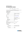
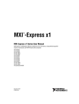
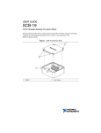
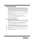
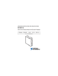
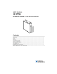
INSTALLATION GUIDE AND TERMINAL BLOCK SPECIFICATIONS NI PXIe-4322 and TB-4322 Français Deutsch ni.com/manuals NI SC Express is a family of PXI Express modules with integrated data acquisition and signal conditioning. These devices offer increased speed, accuracy, and synchronization features that are well suited for high-density sensor measurement and signal-conditioning systems. Accessories required for signal connections to these modules include a front-mount terminal block with screw-terminal connectivity. This guide describes how to install and configure the NI SC Express PXIe-4322 module and terminal block, connect signals, and verify that the system is working properly. Current versions of NI documents are available at ni.com/manuals. The NI PXIe-4322 is an isolated, eight channel analog output module and is designed for use with the TB-4322 terminal block. The keying of this terminal block prevents it from connecting to other modules that could be damaged by the voltage present on the terminal block. However, you should only use this terminal block with its supported modules. Caution When hazardous voltages (>30 Vrms/42.4 Vpk/60 VDC) are present on any terminal, safety low-voltage (≤30 Vrms/42.4 Vpk /60 VDC) cannot be connected to any other terminal. Do not supply hazardous voltages (>30 Vrms/42.4 Vpk/60 VDC) to the terminal block without the terminal block being connected to the NI PXIe-4322. Caution Contents What You Need to Get Started ................................................................................................. 2 Installation ................................................................................................................................3 Install the Software ........................................................................................................... 3 Unpack and Install the Module ......................................................................................... 4 Connect the Signals .......................................................................................................... 5 Install the Terminal Block ................................................................................................ 8 Confirm NI SC Express Module Recognition .................................................................. 9 Run Test Panels ................................................................................................................ 10 Generate an NI-DAQmx Signal........................................................................................ 11 Use Your NI SC Express in an Application ..................................................................... 11 Terminal Block Removal.......................................................................................................... 12 Module Removal....................................................................................................................... 13 Create a Simulated Device........................................................................................................ 14 More Information...................................................................................................................... 14 Troubleshooting ................................................................................................................ 14 Specifications (TB-4322).......................................................................................................... 14 Calibration Interval ........................................................................................................... 14 Electrical ........................................................................................................................... 14 Mechanical........................................................................................................................ 15 Physical ............................................................................................................................. 15 Environmental Specifications ........................................................................................... 15 Shock and Vibration ......................................................................................................... 16 Safety Voltages ................................................................................................................. 16 Safety Standards ............................................................................................................... 17 Electromagnetic Compatibility ......................................................................................... 17 CE Compliance ................................................................................................................. 17 Online Product Certification ............................................................................................. 18 Environmental Management............................................................................................. 18 Where to Go for Support .......................................................................................................... 18 What You Need to Get Started To set up and use the NI PXIe-4322 module and TB-4322 terminal block, you need the following items: 2 Hardware | – TB-4322 terminal block – NI PXIe-4322 module – NI PXI Express chassis – Shielded, twisted-pair cabling and loads as required for your application. ni.com | NI PXIe-4322 and TB-4322 Installation Guide Tools – Number 1 and 2 Phillips-head screwdrivers – 1/8 in. flathead screwdriver – Long-nose pliers – Wire cutter – Wire insulation stripper Documentation – NI PXIe-4322 and TB-4322 Installation Guide and Terminal Block Specifications – Read Me First: Safety and Electromagnetic Compatibility – NI PXIe-4322 User Manual – NI PXI Express chassis user manual You can download needed documents from ni.com/manuals. Installation Install the Software Note You must be an administrator to install NI software and devices on your computer. Before installing the NI SC Express hardware, make sure the following are installed in the order indicated: 1. Your application software, such as LabVIEW, LabWindows™/CVI™, or .NET. 2. NI-DAQmx 9.7 or later. Note When installing NI application software, such as NI LabVIEW, refer to the NI-DAQmx Readme on the software disc for supported software versions. Back up any applications before upgrading software or modifying the application. Using an NI-DAQmx simulated device, you can test NI-DAQmx applications without installing hardware. Refer to the Create a Simulated Device section for instructions for creating NI-DAQmx simulated devices. Tip NI PXIe-4322 and TB-4322 Installation Guide | © National Instruments | 3 Unpack and Install the Module Remove the packaging and inspect the module. Contact NI if the module is damaged. Do not install a damaged module. The module is static sensitive. Always properly ground yourself and the equipment when handling or connecting to the module. Caution Complete the following steps to install the NI SC Express module while referring to Figures 1 and 2: 1. Power off the NI PXI Express chassis. Refer to the chassis manual for chassis installation and configuration instructions. Caution Refer to the Read Me First: Safety and Electromagnetic Compatibility, included with your module, before connecting or disconnecting signal wires. 2. Identify a supported PXI Express slot in the chassis. NI SC Express devices can be placed only in PXI Express Peripheral slots, PXI Express Hybrid Peripheral slots, and PXI Express System Timing slots. Refer to the chassis documentation for details. Figure 1. Symbols for PXI Express, PXI Express Hybrid, and PXI Slots NI PXIe-1062Q 1 1 2 PXI Express System Controller Slot PXI Peripheral Slot 2 3 4 3 4 PXI Express Hybrid Peripheral Slot PXI Express System Timing Slot 3. Remove the filler panel, and touch any metal part of the chassis to discharge static electricity. 4. Place the module edges into the module guides at the top and bottom of the slot. When installing the module, make sure both edges are positioned inside the guides and that the module components do not come into contact with adjacent modules. Caution 5. 4 Slide the module along the guides until it reaches the rear connector, then seat the module by pushing the front panel until it is flush with the front panel of the chassis. | ni.com | NI PXIe-4322 and TB-4322 Installation Guide 6. Secure the module to the chassis using the front-panel captive screws, shown in Figure 2. Tighten the screws to 0.31 N · m (2.7 lb · in.). Figure 2. Installing NI SC Express Modules CO OL ING CL EA RA NC E AN D FA N FIL TE R MA INT EN AN CE RE QU IRE D. SE E MA NU AL . NI PX Ie-1 06 2Q 1 1 Captive Screws Connect the Signals To ensure the specified EMC performance, operate this product only with shielded, twisted-pair cables and shielded accessories. Caution Caution To ensure the specified EMC performance, the length of all I/O cables must be no longer than 30 m (100 ft). Note Refer to the Read Me First: Safety and Electromagnetic Compatibility document before removing equipment covers or connecting or disconnecting any signal wires. To connect signals to the terminal block, refer to Figures 3 and 4 while completing the following steps: Note You can find the pinout names and locations in MAX at any time by right-clicking the device name under Devices and Interfaces and selecting Device Pinouts. 1. Loosen the captive top cover screws and remove the top cover. 2. Loosen the strain-relief screws and remove the strain-relief bar. NI PXIe-4322 and TB-4322 Installation Guide | © National Instruments | 5 3. Prepare the shielded, twisted-pair cable by stripping the insulation and shield(s) to expose sufficient signal wire to connect from just inside the strain relief bar to the desired screw terminal. Ensure that the drain wire of the shielded cable is long enough to connect to one of the two ground lugs inside the terminal block, which are shown in Figure 3. 4. Prepare the signal wire by stripping the insulation no more than 7 mm (0.28 in.). 5. Run the shielded, twisted-pair cable through the strain-relief opening. Figure 3. TB-4322 Parts Locator Diagram 1 6 1 7 2 6 4 3 4 5 8 9 1 2 3 Strain-Relief Screws Strain-Relief Bar Tie Wrap Holes 6. 6 4 5 6 Ground Lugs Terminal Block to Module Connector Captive Top Cover Screws 7 8 9 Top Cover Tie Wraps Signal Wires Insert the stripped end of the signal wires fully into the appropriate terminal. Refer to the label next to each screw terminal to determine the function of the terminal. The NI PXIe-4322 User Manual provides detailed wiring information. Make sure no exposed wire extends past the screw terminal. Exposed wire increases the risk of a short circuit that can cause circuit failure. | ni.com | NI PXIe-4322 and TB-4322 Installation Guide © COPYRIGHT 2012 TB-4322 AO7+ AO7– 3 AO6+ AO6– AO5+ AO5– 3 AO4+ AO4– AO3+ AO3– AO2+ AO2– AO1+ AO1– AO0+ AO0– FOR PATENTS: NI.COM/PATENTS ® Figure 4. TB-4322 Circuit Board Parts Locator Diagram Note Refer to the NI PXIe-4322 User Manual for diagrams showing various ways to connect a load to the TB-4322. 7. Tighten the terminal screws to a torque of 0.2 to 0.25 N · m (1.77 to 2.21 lb · in.). Caution Any wires connected to the ground must be sufficiently insulated from high voltage. 8. Use the ground lugs to attach a shield wire to the ground. Attach the drain wire of the shielded cable to a ground lug. Note 9. Refer to the NI PXIe-4322 User Manual for details about shielding the signals. Reinstall the strain-relief bar and tighten the strain-relief screws. 10. Use tie wraps to connect the signal wires to the tie-wrap holes for additional strain relief when necessary. 11. Reinstall the top cover and tighten the captive top cover screws. Note For information about sensors, go to ni.com/sensors. NI PXIe-4322 and TB-4322 Installation Guide | © National Instruments | 7 Install the Terminal Block Refer to Figure 5 to install the terminal block on the module while completing the following steps: 1. Move the TB-4322 into position in front of the NI PXIe-4322 and engage the alignment feature with the guide on the associated module. Figure 5. Installing the TB-4322 on the NI PXIe-4322 Module 2 1 C LIN O O G C R A LE N A E C N A D N FA TE FIL R N A N TE IN A M E C R U Q E D. E IR E E S AN M . AL U NI PX Ie-1 06 2Q 3 5 6 4 1 2 NI PXIe Controller NI PXIe Chassis 3 4 Mounting Screw TB-4322 Terminal Block 5 6 NI PXIe-4322 Module Alignment Feature 2. Attach the TB-4322 to the NI PXIe-4322 module by pushing the terminal block straight into the module. A spring mechanism will lock in the bottom of the terminal block. 3. Tighten the mounting screw at the top of the TB-4322 to attach it to the NI PXIe-4322 module. For safety purposes and to prevent damage to equipment when high voltages are present, all NI SC Express modules and terminal blocks are keyed to prevent connection between incompatible terminal blocks, modules, and/or cables. Note 4. 8 Power on the chassis. | ni.com | NI PXIe-4322 and TB-4322 Installation Guide Figure 6 shows an example NI SC Express system setup. Figure 6. Sample NI SC Express System CO NI PX Ie-1 06 2 OL ING CL EA RA NC E AN D FA N FIL TE R MA INT EN AN CE RE QU IRE D. SE E MA NU AL . Q 1 2 1 Terminal Block 2 Signal Output Confirm NI SC Express Module Recognition To confirm module recognition, complete the following steps: Make sure you are using the most recent version of NI-DAQmx. If you are using an older version of the driver software, the NI SC Express terminal block may work only in basic functionality mode. Unsupported terminal blocks appear in Measurement & Automation Explorer (MAX) with an X next to them. Note 1. Launch MAX. 2. Expand Devices and Interfaces, and expand NI-DAQmx Devices to confirm that MAX detects the module and terminal block. The terminal block should appear beneath its associated module. If your module or terminal block is not listed, press <F5> to refresh MAX. If the module is still not recognized, go to ni.com/support/daqmx. NI PXIe-4322 and TB-4322 Installation Guide | © National Instruments | 9 Using an NI-DAQmx simulated device, you can test NI-DAQmx applications without installing hardware. Refer to the Create a Simulated Device section for instructions for creating NI-DAQmx simulated devices. Tip 3. Right-click the module name and select Self-Test. When the self-test completes, a verification message appears. If an error occurs, refer to ni.com/support/daqmx. For information about sensors, go to ni.com/sensors. Run Test Panels 1. In MAX, expand Devices and Interfaces»NI-DAQmx Devices. 2. Right-click the device, and select Test Panels. 3. Click Start to test device functions, or Help for operating instructions. To troubleshoot errors, refer to the NI-DAQmx Help, or go to ni.com/support. 10 | ni.com | NI PXIe-4322 and TB-4322 Installation Guide Generate an NI-DAQmx Signal NI-DAQmx Channels and Tasks Refer to the NI-DAQmx Help for complete information about channels and tasks. Use the DAQ Assistant to configure virtual channels and tasks in MAX or in your application. Configure a Task Using the DAQ Assistant from MAX Complete the following steps to create a task using the DAQ Assistant in MAX: 1. In MAX, right-click Data Neighborhood and select Create New to open the DAQ Assistant. 2. Select NI-DAQmx Task and click Next. 3. Select Generate Signals. 4. Select analog output, and the measurement type, such as voltage. 5. Select the physical channel(s) to use and click Next. 6. Name the task and click Finish. 7. Configure the individual channel settings. Each physical channel you assign to a task receives a virtual channel name. To modify the output range or other settings, select the channel. Click Details for physical channel information. Configure the timing and triggering for your task. Click Run. Use Your NI SC Express in an Application For NI software version compatibility, refer to the NI-DAQmx Readme, available from Start» All Programs»National Instruments»NI-DAQmx. To get started with data acquisition in your application software, refer to the tutorials listed in Table 1. Table 1. DAQ Assistant Tutorial Locations Application Tutorial Location LabVIEW Go to Help»LabVIEW Help. Next, go to Getting Started with LabVIEW»Getting Started with DAQ»Taking an NI-DAQmx Measurement in LabVIEW LabWindows/CV I Go to Help»Contents. Next, go to Using LabWindows/CVI»Data Acquisition»Taking an NI-DAQmx Measurement in LabWindows/CVI. Measurement Studio Go to NI Measurement Studio Help»Getting Started with the Measurement Studio Class Libraries»Measurement Studio Walkthroughs»Walkthrough: Creating a Measurement Studio NI-DAQmx Application. LabVIEW SignalExpress* Go to Help»Taking an NI-DAQmx Measurement in SignalExpress. * LabVIEW SignalExpress, an easy-to-use configuration-based tool for data logging applications, is at Start»All Programs»National Instruments»LabVIEW SignalExpress. NI PXIe-4322 and TB-4322 Installation Guide | © National Instruments | 11 Programming Examples NI-DAQmx includes example programs to help you get started developing an application. LabVIEW and CVI examples are located at Help»Find Examples in your application software. Text-based code examples are located at All Programs»National Instruments»NI-DAQ» Text-Based Code Support»ANSI C Examples. Modify example code and save it in an application, or use examples to develop a new application or add example code to an existing application. For other examples, go to ni.com/info and enter the Info Code daqmxexp. For additional examples, refer to zone.ni.com . Terminal Block Removal To remove the terminal block, refer to Figure 7 while completing the following steps: The chassis can be powered on or off when removing the terminal block. Note 1. 2. Loosen the mounting screw located at the top of the terminal block. To remove the terminal block: a. Raise the latch release using a flathead screwdriver to disengage the latch. b. With the latch release raised, grasp the terminal block and pull it away from the module. Figure 7. Removing the TB-4322 from the NI PXIe-4322 Module) 4 3 1 2 CO OLI NG CL EA RA NC E AN D FA N FI LTER MAI NT EN AN CE NI RE QUI RE D. SE EM AN UA L. PX Ie-1 06 2Q 5 1 2 3. 12 Mounting Screw Latch Release 3 4 NI PXIe Controller NI PXIe Chassis Store the terminal block in an antistatic protective bag. | ni.com | NI PXIe-4322 and TB-4322 Installation Guide 5 TB-4322 Terminal Block Module Removal Caution Do not remove a module with the power on. Doing so can damage the module. 1. Make sure that the chassis is powered off before removing the module. 2. Loosen the captive screws on the top and bottom of the module. Caution Do not pull the front panel to remove the module. Doing so may cause module components to come into contact with adjacent modules, causing damage to the modules. 3. Pull the captive screws to unseat the module and slowly slide the module along the guides, as shown in Figure 8. 4. Replace the filler panel in the empty slot. 5. Store the module in an antistatic protective bag. Figure 8. Removing NI SC Express Modules CO OL ING CL EA RA NC E AN D FA N FIL TE R MA INT EN AN CE RE QU IRE D. SE E MA NU AL . NI PX Ie-1 06 2Q 1 1 2 Captive Screws (Use to remove modules.) 2 Front Panel (Do not use to remove modules.) NI PXIe-4322 and TB-4322 Installation Guide | © National Instruments | 13 Create a Simulated Device To run examples without the hardware installed, use an NI-DAQmx simulated device. To create a simulated device in MAX complete the following steps: 1. Launch MAX. 2. Right-click Devices and Interfaces»Create New. 3. From the dialog, select Simulated NI-DAQmx Device or Modular Instrument. 4. Type 4322 in the text box at the top of the window. 5. Select the device from the list provided. 6. Click OK. More Information After you install NI-DAQmx, the NI-DAQmx documentation is available from Start» All Programs»National Instruments»NI-DAQ. Additional resources are online at ni.com/ gettingstarted. You can access online device documentation by right-clicking your module in MAX and selecting Help»Online Device Documentation. A browser window opens to ni.com/ manuals with the results of a search for relevant documents. If you do not have Web access, documents for supported modules are included on the NI-DAQmx disc. Troubleshooting • Go to ni.com/support/install or ni.com/kb. • If you need to return your National Instruments hardware for repair or device calibration, go to ni.com/info and enter rdsenn to start the Return Merchandise Authorization (RMA) process. Specifications (TB-4322) NI PXIe-4322 module specifications are located in the NI PXIe-4322 Specifications document. Note All specifications are typical at 23 °C unless otherwise specified. Calibration Interval TB-4322 ............................................................No calibration Electrical TB-4322 is a feedthrough terminal block. For electrical output characteristics refer to the NI PXIe-4322 Specifications document. 14 | ni.com | NI PXIe-4322 and TB-4322 Installation Guide Mechanical Screw terminal wire gauge ............................... 16 AWG, max Physical Figure 9. TB-4322 Dimensions 6.02 in. (15.28 cm) 5.10 in. (12.95 cm) Weight............................................................... 592 g (20.9 oz) Clean the hardware with a soft, nonmetallic brush. Make sure that the hardware is completely dry and free from contaminants before returning it to service. Caution Environmental Specifications Maximum altitude............................................. 2,000 m (800 mbar), at 25 °C ambient temperature Pollution Degree ............................................... 2 Indoor use only. Operating Environment Ambient temperature range .............................. 0 °C to 55 °C (Tested in accordance with IEC-60068-2-1 and IEC-60068-2-2. Meets MIL-PRF-28800F Class 3 low temperature limit and MIL-PRF-28800F Class 2 high temperature limit.) Relative humidity range.................................... 10% to 90%, noncondensing (Tested in accordance with IEC-60068-2-56.) NI PXIe-4322 and TB-4322 Installation Guide | © National Instruments | 15 Storage Environment Ambient temperature range ..............................-40 °C to 71 °C (Tested in accordance with IEC-60068-2-1 and IEC-60068-2-2. Meets MIL-PRF-28800F Class 3 limits.) Relative humidity range....................................5% to 95%, noncondensing (Tested in accordance with IEC-60068-2-56.) Shock and Vibration Operating shock ................................................30 g peak, half-sine, 11 ms pulse (Tested in accordance with IEC-60068-2-27. Meets MIL-PRF-28800F Class 2 limits.) Random vibration Operating ..................................................5 Hz to 500 Hz, 0.3 grms Non-operating ...........................................5 Hz to 500 Hz, 2.4 grms (Tested in accordance with IEC-60068-2-64. Non-operating test profile exceeds the requirements of MIL-PRF-28800F, Class 3.) Safety Voltages Maximum Voltage Connect only voltages that are within the following limits: Between any two AO+ and AO- pair................±120 VDC Isolation Voltages Channel-to-channel ...........................................300 Vrms, Measurement Category II (Basic) Withstand ..........................................1,500 Vrms Channel-to-earth ground ...................................300 Vrms, Measurement Category II Withstand ..........................................3,000 Vrms Measurement Category II is for measurements performed on circuits directly connected to the electrical distribution system. This category refers to local-level electrical distribution, such as that provided by a standard wall outlet, for example, 115 V for U.S. or 230 V for Europe. Do not connect the TB-4322 to signals or use for measurements within Measurement Categories III or IV. Caution The protection provided by the TB-4322 can be impaired if it is used in a manner not described in this document. Caution 16 | ni.com | NI PXIe-4322 and TB-4322 Installation Guide Safety Standards This product meets the requirements of the following standards of safety for electrical equipment for measurement, control, and laboratory use: • IEC 61010-1, EN 61010-1 • UL 61010-1, CSA 61010-1 Note For UL and other safety certifications, refer to the product label or the Online Product Certification section. Electromagnetic Compatibility This product meets the requirements of the following EMC standards for electrical equipment for measurement, control, and laboratory use: • EN 61326-1 (IEC 61326-1): Class A emissions; Basic immunity • EN 55011 (CISPR 11): Group 1, Class A emissions • EN 55022 (CISPR 22): Class A emissions • EN 55024 (CISPR 24): Immunity • AS/NZS CISPR 11: Group 1, Class A emissions • AS/NZS CISPR 22: Class A emissions • FCC 47 CFR Part 15B: Class A emissions • ICES-001: Class A emissions Note In the United States (per FCC 47 CFR), Class A equipment is intended for use in commercial, light-industrial, and heavy-industrial locations. In Europe, Canada, Australia and New Zealand (per CISPR 11) Class A equipment is intended for use only in heavy-industrial locations. Note Group 1 equipment (per CISPR 11) is any industrial, scientific, or medical equipment that does not intentionally generate radio frequency energy for the treatment of material or inspection/analysis purposes. Note For EMC declarations and certifications, and additional information, refer to the Online Product Certification section. CE Compliance This product meets the essential requirements of applicable European Directives as follows: • 2006/95/EC; Low-Voltage Directive (safety) • 2004/108/EC; Electromagnetic Compatibility Directive (EMC) NI PXIe-4322 and TB-4322 Installation Guide | © National Instruments | 17 Online Product Certification Refer to the product Declaration of Conformity (DoC) for additional regulatory compliance information. To obtain product certifications and the DoC for this product, visit ni.com/ certification, search by model number or product line, and click the appropriate link in the Certification column. Environmental Management NI is committed to designing and manufacturing products in an environmentally responsible manner. NI recognizes that eliminating certain hazardous substances from our products is beneficial to the environment and to NI customers. For additional environmental information, refer to the Minimize Our Environmental Web page at ni.com/environment. This page contains the environmental regulations and directives with which NI complies, as well as other environmental information not included in this document. Waste Electrical and Electronic Equipment (WEEE) At the end of the product life cycle, all products must be sent to a WEEE recycling center. For more information about WEEE recycling centers, National Instruments WEEE initiatives, and compliance with WEEE Directive 2002/96/EC on Waste and Electronic Equipment, visit ni.com/environment/ weee. EU Customers ⬉ᄤֵᙃѻક∵ᶧࠊㅵ⧚ࡲ⊩ ˄Ё RoHS˅ Ёᅶ᠋ National Instruments ヺড়Ё⬉ᄤֵᙃѻકЁ䰤ࠊՓ⫼ᶤѯ᳝ᆇ⠽䋼ᣛҸ (RoHS)DŽ݇Ѣ National Instruments Ё RoHS ড়㾘ᗻֵᙃˈ䇋ⱏᔩ ni.com/ environment/rohs_chinaDŽ (For information about China RoHS compliance, go to ni.com/environment/rohs_china.) Where to Go for Support The National Instruments Web site is your complete resource for technical support. At ni.com/ support you have access to everything from troubleshooting and application development self-help resources to email and phone assistance from NI Application Engineers. National Instruments corporate headquarters is located at 11500 North Mopac Expressway, Austin, Texas, 78759-3504. National Instruments also has offices located around the world to help address your support needs. For telephone support in the United States, create your service request at ni.com/support and follow the calling instructions or dial 512 795 8248. For telephone support outside the United States, visit the Worldwide Offices section of ni.com/ niglobal to access the branch office Web sites, which provide up-to-date contact information, support phone numbers, email addresses, and current events. 18 | ni.com | NI PXIe-4322 and TB-4322 Installation Guide Refer to the NI Trademarks and Logo Guidelines at ni.com/trademarks for more information on National Instruments trademarks. Other product and company names mentioned herein are trademarks or trade names of their respective companies. For patents covering National Instruments products/technology, refer to the appropriate location: Help»Patents in your software, the patents.txt file on your media, or the National Instruments Patents Notice at ni.com/patents. You can find information about end-user license agreements (EULAs) and third-party legal notices in the readme file for your NI product. Refer to the Export Compliance Information at ni.com/legal/export-compliance for the National Instruments global trade compliance policy and how to obtain relevant HTS codes, ECCNs, and other import/export data. © 2013 National Instruments. All rights reserved. 375957A-01 Apr13