1
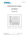
Product Manual
BJ194Y-9SY Power Analyzer
User Manual
Version:
:1.5
Tel: +0086-023-86850812
Email:[email protected]
Fax:+0086-023-67636974
Add: Building 13, 2-8, Jialing third village Pioneer Park, Jiangbei District, Chongqing
Product Manual
Read me
When you use BJ194Y-9SY series Power Analyzer, be sure to read this user manual
carefully, and be able to fully understand the implications, the correct guidance of
operations in accordance with user manual, which will help you make better use of
BJ194Y-9SY series Power Analyzer, and help to solve the various problems at the scene.
1. Before the meter turning on the power supply, be sure that the power supply within the
provisions of the instrument;
2. When installation, the current input terminal must non-open, voltage input terminals must
Non-short circuit;
3. Communication terminal (RS232/RS485 or Ethernet) is strictly prohibited to impose on high
pressure;
4. Be sure the instrument wiring consistent with the internal system settings;
5. When communicating with the PC, instrument communication parameters must be consistent
with the PC.
● Please read this user manual carefully
● Please save this document
Tel: +0086-023-86850812
Email:[email protected]
Fax:+0086-023-67636974
Add: Building 13, 2-8, Jialing third village Pioneer Park, Jiangbei District, Chongqing
-1-
Product Manual
Directory
CONTENTS
Page
1. SUMMARIZE--------------------------------------------------------------------------------------------------------- 3
2. APPLICATIONS --------------------------------------------------------------------------------------------------- 3
3. FEATURES --------------------------------------------------------------------------------------------------------- 4
3.1. - Electricity metering ---------------------------------------------------------------------------------------- 4
3.2. - Specifications ----------------------------------------------------------------------------------------------- 5
4. INSTALLATION AND START-UP ------------------------------------------------------------------------------ 7
4.1. - Installation ----------------------------------------------------------------------------------------------------7
4.2. - Connection Terminal ------------------------------------------------------------------------------------- 9
4.3. - Connection Drawing---------------------------------------------------------------------------------------10
5. SCREEN DISPLAY------------------------------------------------------------------------------------------------11
6. OPERATION MODE --------------------------------------------------------------------------------------------- 12
7. SETUP PROCEDURE ------------------------------------------------------------------------------------------- 18
7.1.- Input Password-----------------------------------------------------------------------------------------------18
7.2. - Input Signal Selection ------------------------------------------------------------------------------------18
7.3. - Communication Preferences-----------------------------------------------------------------------------22
7.4. - Digital Output Setting--------------------------------------------------------------------------------------24
7.5. - Analog Output Setting-------------------------------------------------------------------------------------28
7.6. - Time and Date Setting-------------------------------------------------------------------------------------31
7.7. - Muti-tariff Setting--------------------------------------------------------------------------------------------34
7.8. - System Setting----------------------------------------------------------------------------------------------36
7.9. - Menu Structure----------------------------------------------------------------------------------------------38
7.10. - Display Character instructions-------------------------------------------------------------------------40
8. PULSE OUTPUT --------------------------------------------------------------------------------------------------41
9. SAFETY CONSIDERATIONS--------------------------------------------------------------------------------- 42
10. MAINTENANCE---------------------------------------------------------------------------------------------------42
11. TECHNICAL SERVICE----------------------------------------------------------------------------------------- 43
Tel: +0086-023-86850812
Email:[email protected]
Fax:+0086-023-67636974
Add: Building 13, 2-8, Jialing third village Pioneer Park, Jiangbei District, Chongqing
-2-
Product Manual
1. - SUMMARIZE
BJ194Y-9SY series Power Analyzer is a high-end multifunction power meter. It is the ideal choice
for monitoring and measuring of power systems.
It can measure all of the power parameters in power grid:
Current,
Voltage,
Frequency,
Active power,
Reactive power,
Apparent power,
Energy,
Power factor,
Current harmonics 2~15 times,
Voltage harmonics 2~15 times,
Voltage and current THD%,
Multi- tariffs ratio.
And it can also transmit the parameter into 2 route relay output and 4 route switch input, 1
route analog output. For transformers, generators, capacitor banks and motors of the distributed
detection, automatic control system, on-line monitoring display.
It can replace the traditional analog or many digital measurement instruments (such as
ammeter, voltmeter, power meter, power factor meter, frequency meter, etc.) with the advantages
of improving system reliability, making the on-site wiring convenient and reduce system cost.
With serial port, BJ194Y-9SY Power Analyzer can connect with PC; and use Modbus to set
programming and read the data.
Based on this power meters, you can simply set up a monitoring system with the IPC and
central software.
2. - APPLICATIONS
◆ All power parameter measurement;
◆ Power factor measurement and control;
◆ Energy Measurement;
◆ Replacing the three-phase power meter, three phase electricity transmitter;
◆ Transformers, generators, capacitors and electric motors distributed detection;
◆ Medium and low pressure systems;
◆ SCADA, EMS, DCS integrators.
Tel: +0086-023-86850812
Email:[email protected]
Fax:+0086-023-67636974
Add: Building 13, 2-8, Jialing third village Pioneer Park, Jiangbei District, Chongqing
-3-
Product Manual
3. - FEATURES
3.1. - Electricity Metering
By means of an internal microprocessor it simultaneously measures:
Parameter
Symbol
A-phase
B-phase
C-phase
Total
Single phase voltage
V
x
x
x
/
*Phase-phase voltage
V
x
x
x
/
Current
A
x
x
x
/
Frequency
Hz
/
/
/
x
Power factor
Cos Φ
xx
xx
xx
x
Active power
W
xx
xx
xx
x
Reactive power
Var
xx
xx
xx
x
Active energy
Wh
/
/
/
x
Reactive energy
Varh
/
/
/
x
Voltage THD
THD%V
x
x
x
/
Current THD
Individual harmonic current
content (Up to the 15 th)
THD%A
x
x
x
/
x
x
x
/
Notes: Phase-phase voltage is Uab, Ubc, Uca, voltage data determined by the different wiring
Available: x: Display and communications.
xx: Only can read in RS485 communication
The 194Y-9SY delivers the visualization of parameters listed above by means of LCD type
displays. In the main display area shows 4 power parameters, with other display area show the
various parameters and state of meter on each page jump.
OTHER FEATURES
- Low-size (96 x 96 mm), panel-mounting meter.
- True R.M.S. measuring system.
- Instantaneous, maximum and minimum values of each measured parameter.
- Energy measurement (indication through a lighting led)
- RS-485 or Ethernet(optional) type communication to a PC.
Tel: +0086-023-86850812
Email:[email protected]
Fax:+0086-023-67636974
Add: Building 13, 2-8, Jialing third village Pioneer Park, Jiangbei District, Chongqing
-4-
Product Manual
3.2. - Specifications
1. - Reference standard:
Basic electricity: GB/T13850-1998 (IEC688-1992)
Active power: GB/T17215-2002 (IEC61036:2000)
Reactive power: GB/T17882-1999 (IEC61268:1995)
2- Accuracy standards
Parameter
Accuracy
A phase
B phase
C phase
Voltage
Current
Active Power
Reactive Power
Apparent power
Power Factor
Active Energy
Reactive Energy
Frequency
0.5%fs
0.5%fs
0.5%fs
0.5%fs
0.5%fs
0.5%fs
1%rd
2%rd
0.05%rd
V1
A1
W1
var1
VA1
PF1
V2
A2
W2
var2
VA2
PF2
V3
A3
W3
var3
VA3
PF3
All
Averag
e
VE
AE
W
var
VA
PF
Wh
varh
Hz
3. - Input
Voltage: Rated 400V (optional 100V)
Current: Rated 5A (optional 1A)
Frequency: 45-65Hz
4. - Load
Voltage: <0.5VA / phase (rated 220V)
Current: <0.5VA / phase (rated 5A)
5. - Overload
Current: 1.2 times rated continuous; 10 seconds for 10 times the rated
Voltage: 1.2 times the rated continuous; 10 seconds for 800V
6. - Dielectric strength
IEC 688 / IEC 255-3 (1989)
2kV AC RMS 1 minute, between input / output / case / power supply
Tel: +0086-023-86850812
Email:[email protected]
Fax:+0086-023-67636974
Add: Building 13, 2-8, Jialing third village Pioneer Park, Jiangbei District, Chongqing
-5-
Product Manual
7. - EMC Test
Electrostatic discharge immunity
test:
Electrical fast transient burst
immunity test
Surge (Shock) immunity test
standard
Test voltage
IEC-61000-4-2
level 4
8Kv
IEC61000-4-4
level 3
Input 1kV; Power supply 2kV
IEC61000-4-5
level 4
common mode test voltage
4kV
8. - Work environment
Temperature: -20
℃~ +60℃
Humidity: RH 20%~95%(No condensation)
9. - Protection
Panel: IP54
Case: IP20
10. - Storage Conditions
℃
℃
Temperature: -25 ~+70
Humidity: RH 20%~95%
11. - Working Power
AC 80-265V, 45-65Hz, DC 80-380V
DC 20-60V (Optional)
Maximum power consumption 6W
12. - Dimensions
L × W × H =96mm×96mm×71mm
13. - Installation hole size
L × W = (91+0.8mm) × (91+0.8mm)
Tel: +0086-023-86850812
Email:[email protected]
Fax:+0086-023-67636974
Add: Building 13, 2-8, Jialing third village Pioneer Park, Jiangbei District, Chongqing
-6-
Product Manual
4.- INSTALLATION AND START-UP
The manual you hold in your hand contains information and warnings that the user
should respect in order to guarantee a proper operation of all the instrument
functions and keep it in safety conditions. The instrument must not be powered on
and used until its definitive assembly is on the cabinet’s door.
If the instrument is not used as manufacturer’s specifications, the protection of the
instrument will be damaged.
When any protection failure is suspected to exist (for example, it presents external visible
damages),the instrument must be immediately powered off. In this case contact a qualified
service representative.
4.1.- Installation
Mounting
Instrument is to be mounted on panel (cut-out 91+0.8 x 91+0.8 mm). Keep all connections
into the cabinet.
Note that with the instrument powered on, the terminals could be dangerous to touch
and cover opening actions or elements removal may allow accessing dangerous parts.
Therefore, the instrument must not be used until this is completely installed.
Front view
Side view
Tel: +0086-023-86850812
Email:[email protected]
Fax:+0086-023-67636974
Add: Building 13, 2-8, Jialing third village Pioneer Park, Jiangbei District, Chongqing
-7-
Product Manual
Notes:
Input signal: BJ194Y using a separate acquisition calculate for each measurement channel, to
ensure consistent in use, for different load forms, its a variety of connection mode. Access wire
shall be met: the current 2.5 square mm, voltage of 1.5 square millimeters.
A. Voltage input:
Input voltage should not exceed the rated input voltage products (100V or 400V),
Otherwise, you should use external CT. Suggest 1A fuse be installed in the voltage input side.
B. Current Input:
Standard input current is 5A, if greater than 5A should use external CT.
When the CT is connected with other instruments, make sure wiring methods be used in series.
Before remove the current input connection, must be sure to disconnect the primary circuit or
shorted secondary circuit of CT. In order to facilitate disassembly, please do not connect to CT
directly, and the terminal block is suggested.
C. Please make sure that the input voltage and current corresponding to the same phase
sequence, and the same direction; Otherwise, the Values and symbols will be wrong!!
(Power and Energy)
The input network configuration of instrument depends on the CT number of the system:
in the condition of 2 CT, select the three-phase, three-lines two components;
in the condition of 3 CT, select the three-phase, four-lines three component mode.
Instrument connection mode, set of the instrument (programming input network NET)
should be the same load wiring as measured wiring. Otherwise, the measurement instrument
will lead to incorrect voltage or power.
In three-phase three-wire mode, the measurement and shows the line voltage;
In three-phase four-wire mode, the measurement and shows the phase voltage.
Auxiliary power:
BJ194Y Series Power Analyzer with universal (AC / DC) power input, if not for a special
statement, we provide the 220VAC/DC or 110VAC/DC power interface for standard products.
Instruments limit work power supply: AC / DC: 80-270V, please ensure that the auxiliary power
can match with BJ194Y series meter to prevent damage to the product.
A. Suggest install 1A fuse in the fire line side.
B. For the areas with poor power quality, suggest install lightning surge suppressor and rapid
burst suppressor to prevent lightning strikes.
Tel: +0086-023-86850812
Email:[email protected]
Fax:+0086-023-67636974
Add: Building 13, 2-8, Jialing third village Pioneer Park, Jiangbei District, Chongqing
-8-
Product Manual
4.2. - Connection Terminal
Upper connection terminal
15
16
50
49
48
47
60
59
58
2
AO-
AO+
RP-
RP+
AP-
AP+
GUD
RS485B
RS485A
1
Power supply
1. *Supply voltage input: 0 V
47. Active energy pulse output (+)
2. *Supply voltage input: 220 Va.c.
48. Active energy pulse output (-)
58. RS-485 ( + )
49. Reactive energy pulse output (+)
59. RS-485 ( - )
50. Reactive energy pulse output (-)
60. RS-485 ( GND )
16. Analog output (+)
15. Analog output (–)
Middle connection terminal
22
21
20
DO2
19
DO1
70
71
72
73
74
COM
DI1+
DI2+
DI3+
DI4+
20. Route 1 digital output (+)
70. Digital input COM pin
19. Route 1 digital output (-)
71. Route 1 digital input (+)
22. Route 2 digital output (+)
72. Route 2 digital input (+)
21. Route 2 digital output (-)
73. Route 3 digital input (+)
74. Route 4 digital input (+)
Lower connection terminal
14
13
12
11
Un
Uc
Ub
Ua
9
8
C-phase Current
7
6
B-phase Current
5
4
A-phase Current
4. Current A-phase - S1 input
9. Current C-phase - S2 input
5. Current A-phase - S2 input
11. Voltage A-phase input
6. Current B-phase - S1 input
12. Voltage B-phase input
7. Current B-phase - S2 input
13. Voltage C-phase input
8. Current C-phase - S1 input
14. Neutral Voltage input
Tel: +0086-023-86850812
Email:[email protected]
Fax:+0086-023-67636974
Add: Building 13, 2-8, Jialing third village Pioneer Park, Jiangbei District, Chongqing
-9-
Product Manual
4.3. - Connection Drawing
IMPORTANT REMARK!
If power = -0.01 is shown for any of the phases and voltage and current are not zero for this
phase, check out following points:
- Assure that A, B and C phases coincide in voltage and current.
- Correct polarity? Reverse the current transformer placed at this phase.
Note: This connection drawing is for reference only, the actual connecting terminal please refer to
the label on the rear part.
Tel: +0086-023-86850812
Email:[email protected]
Fax:+0086-023-67636974
Add: Building 13, 2-8, Jialing third village Pioneer Park, Jiangbei District, Chongqing
- 10 -
Product Manual
5. SCREEN DISPLAY
5.1. - Panel Diagram
`
Note: Please see detail instructions of “*” items at “OPERATION MODE”.
Tel: +0086-023-86850812
Email:[email protected]
Fax:+0086-023-67636974
Add: Building 13, 2-8, Jialing third village Pioneer Park, Jiangbei District, Chongqing
- 11 -
Product Manual
6. - OPERATION MODE
When the 194Y-9SY is powered up, the entire symbol will be on, and the meter starts to selftest. After some seconds, the meter is ready for operation and shows one of the available
screens.
Parameters on display can be switched by pressing key
screen at any moment
When the key
showing.
or
.
LCD shown on
is pressed, the screen CURRENT values of each phase are now
Pressing again the key
, the screen will show the following parameters successively.
In setting menu, pressing key
Pressing
can move the setting cursor to left;
can enter the number 0 ~ 9.
This key named "SET" key, pressing it can open the programming menu and return to
previous menu.
This key named “Enter” key, pressing this key you can exit it with saving any modification
that you might have done, in menu operation press “Enter” key, and user can go to the next
menu.
Note:
Press key
in main screen:
or
in normal standby status, and the meter will show different data
In the menu set mode, when changes the parameter and exit setting, the meter will ask to
"SAVE", press
exit without saving
press
save and exit.
Tel: +0086-023-86850812
Email:[email protected]
Fax:+0086-023-67636974
Add: Building 13, 2-8, Jialing third village Pioneer Park, Jiangbei District, Chongqing
- 12 -
Product Manual
Screen 1: Displays the three phase voltage Ua, Ub, Uc;
As shown: Ua = 380.0V; Ub = 380.0V; Uc = 380.0V;
In the bottom character “Ep” show total active energy is 83.6KWh.
In other display area region show the system information:
DI1, DI2, DI3, DI4 in the close state;
DO1, DO2 in the open state;
Communication transceiver normal;
Note: Detail information for each symbol, please refer chapter 5, following sections as same
Note: in the high voltage measurement, X103 mean the showing voltage value multiplied by
1000, in the screen diagram mean the voltage is 10X1,000=10,000volt
Tel: +0086-023-86850812
Email:[email protected]
Fax:+0086-023-67636974
Add: Building 13, 2-8, Jialing third village Pioneer Park, Jiangbei District, Chongqing
- 13 -
Product Manual
Screen 2: Display the three-phase current Ia, Ib, Ic.
In the bottom Ep shows total negative active energy.
Screen 3: Display the total active power, total reactive power, and total factor.
In the bottom “Eq” shows total active energy.
Note: In power data screen, user can press key “
Independent three phase active power;
Independent three phase reactive power;
Independent three phase e powerfactor.
” switch show:
Tel: +0086-023-86850812
Email:[email protected]
Fax:+0086-023-67636974
Add: Building 13, 2-8, Jialing third village Pioneer Park, Jiangbei District, Chongqing
- 14 -
Product Manual
Screen 4: Display the frequency of a phase.
In the bottom “Eq” shows total negative reactive energy.
Screen 5: Display the 4 tariff energy data.
In the top screen “T1”~”T4” indicate current showing tariff.
In diagram show tariff_2
E0~E3 indicate the last three month
E0: Three month total energy data
E1: Last month energy
E2: Last month energy
E3: Month before last month energy
In the bottom screen “T1”~”T4” indicate the energy sum data in each tariff.
Note: Press key “
” can switch show other energy data
Tel: +0086-023-86850812
Email:[email protected]
Fax:+0086-023-67636974
Add: Building 13, 2-8, Jialing third village Pioneer Park, Jiangbei District, Chongqing
- 15 -
Product Manual
Screen 6: Display real-time clock,
The first line shows year,
Second line shows month,
Third line shows date;
In the bottom line shows:
Hour, minute and second.
Screen 7: Display the voltage THD%.
Screen 8: Display the current THD%.
Tel: +0086-023-86850812
Email:[email protected]
Fax:+0086-023-67636974
Add: Building 13, 2-8, Jialing third village Pioneer Park, Jiangbei District, Chongqing
- 16 -
Product Manual
Screen 9: Display voltage harmonic data, press
Screen 10: Display current harmonic data, press
can show the 2~15 times data.
can show the 2~15 times data.
Tel: +0086-023-86850812
Email:[email protected]
Fax:+0086-023-67636974
Add: Building 13, 2-8, Jialing third village Pioneer Park, Jiangbei District, Chongqing
- 17 -
Product Manual
7. - SETUP PROCEDURE
The SETUP procedure of the BJ194Y-9SY is performed by means of several SETUP options.
Once into the SETUP, use the keyboard to select different options and enter required variables:
7.1.- Input Password
A 4-figure password is required to be entered (in case that in case that the meter will work
without permission.)
At normal display mode, press
Meter display “
to enter the programming mode, meter display
”,
Ask for the password. Press
to input the password number, from “0~9”. Press
to move the cursor . After password switch press
to confirm the input.
If password is correct, meter can enter next setting.
Notes: the default password is 0001.
7.2. - Input Signal Selection
Press
, return to level 1 menu.
In this section, user will set:.
1. Input net mode;
2. Voltage measure range;
3. Current measure range;
4. Voltage transformation ratio;
5. Current transformation ratio.
Tel: +0086-023-86850812
Email:[email protected]
Fax:+0086-023-67636974
Add: Building 13, 2-8, Jialing third village Pioneer Park, Jiangbei District, Chongqing
- 18 -
Product Manual
7.2.1.- Choice the input net mode
In level 1 menu, use
then press
to choose item “-IN-”, and the meter shows like this:
, enter the level 2 menu, choose “LINE”, meter shows:
Then press
Use
and
again, enter the level 3 menu.
and
to select the right wiring mode, meter shows like this:
Or
Note: Selecting the wiring mode must match with actual wiring, or the reading data will go
wrong.
7.2.2.- Voltage measure range
In level 1 menu of “-IN-”
Choose item “U.SCL”, and the meter shows like this:
then press
, enter the level 3 menu, user can see the voltage range:
Tel: +0086-023-86850812
Email:[email protected]
Fax:+0086-023-67636974
Add: Building 13, 2-8, Jialing third village Pioneer Park, Jiangbei District, Chongqing
- 19 -
Product Manual
or
100V: Maximum measured value is 100V
380V: Maximum measured value is 380V
Note: A different range will affect the accuracy of measurements. If the accuracy is 0.5.
Select 100V range, means the minimum scale value is 0.5V (100 x 0.5%);
Select 380V range, means the minimum scale value is 1.9V (380 x 0.5%).
7.2.3.- Current measure range
In level 1 menu of “-IN-”.
Choose “I.SCL”, meter shows like this:
then press
, enter the level 3 menu, user can see the current range:
Or
5A: Maximum measured value is 5A.
1A: Maximum measured value is 1A.
Note: Select a different range will affect the accuracy of measurements, if the accuracy is 0.5.
Select 1A range, means the minimum scale value is 0.005A (1 x 0.5%);
Select 5A range, means the minimum scale value is 0.025A (5 x 0.5%).
7.2.4- Voltage transformation ratio
In level 1 menu of “-IN-”.
Choose item “r.PT” , meter shows like this:
Tel: +0086-023-86850812
Email:[email protected]
Fax:+0086-023-67636974
Add: Building 13, 2-8, Jialing third village Pioneer Park, Jiangbei District, Chongqing
- 20 -
Product Manual
then press
Press
, enter the level 3 menu, allowing us to set the current transformer.
to input the number, from “0~9”. Press
password switch press
to move the cursor. After
to confirm the input, value is 1~9999.
Note: The input values represent the voltage transformer (primary side voltage) / (secondary
side voltage).
Secondary side voltage is 100V or 380V; user set it at section 7.2.2
7.2.5. - Current transformation ratio
In level 1 menu of “-IN-”.
Choose the item “r.CT”, meter shows like this:
then press
Press
, enter the level 3 menu, allowing us to set the current transformer.
to input the number, from “0~9”. Press
password switch press
to move the cursor. After
to confirm the input, value is 1~9999.
Note: The input values represent the current transformer (primary side voltage) / (secondary
side current) .
Secondary side current is 1A or 5A, user set it at section 7.2.3
Tel: +0086-023-86850812
Email:[email protected]
Fax:+0086-023-67636974
Add: Building 13, 2-8, Jialing third village Pioneer Park, Jiangbei District, Chongqing
- 21 -
Product Manual
7.3. - Communication Preferences
Press
, return to level 1 menu.
In this section, user will set:
1. Meter communication address;
2. Baud rate;
3. Communication format.
Note: Not all the meter have communication function, please make sure your purchase
meter first, if no communication mode, you can skip this section.
7.3.1. - Meter communication address setting
One or some BJ194Vmeter can be connected to a P.C. With this system we can get all the
parameters in one central point of reading. The BJ194..., has a serial RS-485 or RS-232 type
output (according to the model). If we connect more than one device to the same communication
line (RS-485), we have to assign to each of them a different code or direction (from 1 to 247),
since the P.C. needs the identification of every measuring point.
In level 1 menu, choose the item “bus”, the meter shows like this:
Then press
Press
, enter the level 2 menu, choose the item “Addr”, the meter shows like this:
to input
password, press
the number, from “0~9”. Press
to move the cursor. After
to confirm the input, value is 1~9999.
Tel: +0086-023-86850812
Email:[email protected]
Fax:+0086-023-67636974
Add: Building 13, 2-8, Jialing third village Pioneer Park, Jiangbei District, Chongqing
- 22 -
Product Manual
7.3.2.- Communication Baud rate setting
In level 1 menu of “bus”.
Choose item “BAUD”, and the meter shows like this:
Then press
9600.
, enter the level 3 menu, allowing us to set the Baud rate 2400, 4800 or
or
or
7.3.3.- Choose communication format
In level 1 menu of “bus”.
Choose item “data”, and the meter shows like this:
Then press
, enter the level 3 menu, allowing us to set the communication data format.
(Factory setting n.8.1)
or
or
Tel: +0086-023-86850812
Email:[email protected]
Fax:+0086-023-67636974
Add: Building 13, 2-8, Jialing third village Pioneer Park, Jiangbei District, Chongqing
- 23 -
Product Manual
7.4. - Digital Output Setting
Press
, return to level 1 menu.
In this section, user will set:
1. Digital output type;
2. Output delay;
3. Choose the electrical parameter;
4. Set the alarm value
5. Set the hysteresis value
Note: If the meter have more than one channel digital output, you can set the
DO-2,DO-3Has the following step, please select the appropriate output
settings in the level 1 menu,.
7.4.1. - Output type
In level 1 menu, use
and
to choose item “DO-1”, and the meter shows like this:
then press
, enter the level 2 menu, choose “TYPE”. The meter shows:
then press
again, enter the level 3 menu.
Use
and
to select the output type, meter shows like this:
Or
or
Tel: +0086-023-86850812
Email:[email protected]
Fax:+0086-023-67636974
Add: Building 13, 2-8, Jialing third village Pioneer Park, Jiangbei District, Chongqing
- 24 -
Product Manual
r.n: Mean remote control mode, there have pulse and level output mode, more detail refer
chapter 7.4.2.
Host inquiry:
01
Address
05
00 01
Code
Relay address
Slave answer
01
05
Address
Code
00 01
Relay address
FF 00
Relay value
(FF00:close; 0000: open)
DD FA
FF 00
Relay value
(FF00:close; 0000: open)
DD FA
CRC
CRC
RS485 communication please refer to RS485 protocol document.
ALr: Mean directly alarm mode
OFF: Mean the relay will not work
7.4.2. - Set output delay
In level 1 menu of “DO-1”.
Choose item “DELY”, and the meter shows like this:
Then press
Press
, enter the level 3 menu, user can set the delay value:
to input the number, from “0~9”. Press
password switch press
to move the cursor. After
to confirm the input, value is 1~9999. (Default 0010)
Note: The setting of relay value is indicating the width pulse output; value “0000” is for level
output. The setting value resolution is 100ms, which means “0001” is 100ms, “9999”
means 999.9s. 0 for level output, 1~9999 for pulse output
Tel: +0086-023-86850812
Email:[email protected]
Fax:+0086-023-67636974
Add: Building 13, 2-8, Jialing third village Pioneer Park, Jiangbei District, Chongqing
- 25 -
Product Manual
7.4.3. - Choose the electrical parameter
In level 1 menu of “DO-1”.
Choose item “PArA”, meter shows like this:
then press
, enter the level 3 menu, user can choose the output parameter:
Note: There are two alarm mode, indicate with “XX-H” and “XX-L”,
“XX-H” mean the rising edge alarm;
“XX-L” mean the falling edge alarm;
Example: “IA-H” mean when the A-phase current is rising to a certain value then output alarm.
“I3-H” mean when one phase of A, B, C phase current is rising to a certain value then
output alarm.
“PS-L” mean when Three-phase total power is falling to a certain value then output
alarm.
7.4.4. - Set the alarm value
In level 1 menu of “DO-1”.
Choose item “VALU”; meter shows like this:
then press
, enter the level 3 menu, user can set the alarm value:
Tel: +0086-023-86850812
Email:[email protected]
Fax:+0086-023-67636974
Add: Building 13, 2-8, Jialing third village Pioneer Park, Jiangbei District, Chongqing
- 26 -
Product Manual
Press
to input the number, from “0~9”. Press
password switch press
to move the cursor. After
to confirm the input, value is 1~9999. (Default 5500)
Note: Alarm value is about the secondary side value (such as AC100V, AC5A).
Voltage unit is 0.1V;
Current unit is 0.001A;
Active power unit is 0.1W;
Reactive power unit is 0.1VAR;
Power factor Is 0.001;
Frequency 0.01HZ;
7.4.5. - Set the hysteresis value
In level 1 menu of “DO-1”.
Choose item “HYS”, meter shows like this:
then press
Press
, enter the level 3 menu, and user can set the alarm value:
to input the number, from “0~9”. Press
password switch press
to move the cursor. After
to confirm the input, value is 1~9999. (Default 5500)
Note: hysteresis value is for preventing the relay repeated action.
Example: Alarm value 3.700A; hysteresis value 0.030A; Rising edge alarm
Measured value is 3.700A then relay action, output alarm;
When measured value is bellow 3.670A, the relay will be closed.
Tel: +0086-023-86850812
Email:[email protected]
Fax:+0086-023-67636974
Add: Building 13, 2-8, Jialing third village Pioneer Park, Jiangbei District, Chongqing
- 27 -
Product Manual
7.5. - Analog Output Setting
Press
, return to level 1 menu.
In this section, user will set:
1. Analog output type;
2. Choose the electrical parameter;
3. Set the zero value for transmission output;
4. Set the full scale value for transmission output.
Note: If the meter have more than one channel analog output, you can set the
AO-2,AO-3Has the following steps, please select the appropriate output
settings in the level 1 menu,.
7.5.1. - Output type
In level 1 menu, use
and
to choose item “DO-1”, meter shows like this:
then press
, enter the level 2 menu, choose “LINE”, meter shows:
then press
again, enter the level 3 menu.
Use
and
to select the output type, meter shows like this:
or
or
Note: output type can choose 12~20mA,4~20mA,0~20mA (default is 12~20mA)
Tel: +0086-023-86850812
Email:[email protected]
Fax:+0086-023-67636974
Add: Building 13, 2-8, Jialing third village Pioneer Park, Jiangbei District, Chongqing
- 28 -
Product Manual
7.5.2. - Choose the electrical parameter
In level 1 menu of “AO-1”.
Choose item “PArA”, meter shows like this:
then press
, enter the level 3 menu, user can choose the output parameter:
Note: The analog parameter can set Ia, Ib, Ic, Ua, Ub, Uc, P, Q, H, F; default is UA.
7.5.3. - Set the low value for transmission output
In level 1 menu of “AO-1”.
Choose item “LDIS”, meter shows like this:
then press
Press
, enter the level 3 menu, user can set the low value:
to input the number, from “0~9”. Press
password switch press
to move the cursor. After
to confirm the input, value is 1~9999. (Default 0000)
Tel: +0086-023-86850812
Email:[email protected]
Fax:+0086-023-67636974
Add: Building 13, 2-8, Jialing third village Pioneer Park, Jiangbei District, Chongqing
- 29 -
Product Manual
Note: Alarm value is about the secondary side value (such as AC100V, AC5A).
Voltage unit is 0.1V;
Current unit is 0.001A;
Active power unit is 0.1W;
Reactive power unit is 0.1VAR;
Power factor Is 0.001;
Frequency 0.01HZ;
7.5.4. - Set the full scale value for transmission output.
In level 1 menu of “AO-1”.
Choose item “HDIS”, meter shows like this:
then press
Press
, enter the level 3 menu, user can set the full scale value:
to input the number, from “0~9”. Press
password switch press
to move the cursor. After
to confirm the input, value is 1~9999. (Default 5000)
Note: Alarm value is about the secondary side value (such as AC100V, AC5A).
Voltage unit is 0.1V;
Current unit is 0.001A;
Active power unit is 0.1W;
Reactive power unit is 0.1VAR;
Power factor Is 0.001;
Frequency 0.01HZ;
7.5.5. - Example of analog output.
Set analog output:
TYPE 4-20mA;
PARA select Ia;
LdIS 0000;
HdIS 5000
This mean when A-phase current is 0.000A output 4mA, current is 5.000A output 20mA;
Tel: +0086-023-86850812
Email:[email protected]
Fax:+0086-023-67636974
Add: Building 13, 2-8, Jialing third village Pioneer Park, Jiangbei District, Chongqing
- 30 -
Product Manual
7.6. - Time and Date Setting
Press
, return to level 1 menu.
In this section, user will set the meter system time, which will affect the function of Muti-tariff:
7.6.1. - Set year
In level 1 menu, use
and
to choose item “TIME”, meter shows like this:
then press
, enter the level 2 menu;choose “YEAR”, meter show:
then press
again, enter the level 3 menu.
Use
and
to select the year, setting value from 00-99:
7.6.2. - Set month
In level 1 menu of “TIME”.
Choose item “MON”, meter shows like this:
then press
Use
again, enter the level 3 menu.
and
to select the month, with setting value from 1-12:
Tel: +0086-023-86850812
Email:[email protected]
Fax:+0086-023-67636974
Add: Building 13, 2-8, Jialing third village Pioneer Park, Jiangbei District, Chongqing
- 31 -
Product Manual
7.6.3. - Set week day
In level 1 menu of “TIME”.
Choose item “DAY”, meter shows like this:
then press
Use
again, enter the level 3 menu.
and
to select the day, with setting value from 1-31:
7.6.4. - Set date
In level 1 menu of “TIME”.
Choose item “DATE”, meter shows like this:
then press
Use
again, enter the level 3 menu.
and
to select the week day, with setting value from 1-7:
7.6.5. - Set hour
In level 1 menu of “TIME”.
Choose item “HOUR”, meter shows like this:
then press
Use
again, enter the level 3 menu.
and
to select the hour, setting value from 00-23:
Tel: +0086-023-86850812
Email:[email protected]
Fax:+0086-023-67636974
Add: Building 13, 2-8, Jialing third village Pioneer Park, Jiangbei District, Chongqing
- 32 -
Product Manual
7.6.6. - Set minute
In level 1 menu of “TIME”.
Choose item “MIN”, meter shows like this:
then press
Use
again, enter the level 3 menu.
and
to select the minute, with setting value from 00-59:
7.6.7. - Set second
In level 1 menu of “TIME”.
Choose item “SEC”, meter shows like this:
then press
Use
again, enter the level 3 menu.
and
to select the second, setting value from 00-59:
7.6.8. - Set billing date
In level 1 menu of “TIME”.
Choose item “E.DAY”, meter shows like this:
then press
again, enter the level 3 menu. Meter will show:
Tel: +0086-023-86850812
Email:[email protected]
Fax:+0086-023-67636974
Add: Building 13, 2-8, Jialing third village Pioneer Park, Jiangbei District, Chongqing
- 33 -
Product Manual
Use
and
to select the billing date:
Note: Default value is 0101, mean the billing date is At 1:00 on the 1st of each month.
So the setting value max is 3123, which means each month 31st, 23:00
Date : time
7.7. - Muti-tariff Setting
Press
, return to level 1 menu.
In this section, user will set:
1. Billing segment setting;
2. Ttariff setting
Note: BJ-194Y contains 12 billing segments, with the billing segment 1 setting method
in this manual.
7.7.1. - Set the billing time of segment 1
In level 1 menu, use
and
to choose item “S.EG1”, and the meter shows like
this:
Then press
Then press
, enter the level 2 menu, choose “TIME”. The meter shows:
again, entering the level 3 menu.
Tel: +0086-023-86850812
Email:[email protected]
Fax:+0086-023-67636974
Add: Building 13, 2-8, Jialing third village Pioneer Park, Jiangbei District, Chongqing
- 34 -
Product Manual
Use
and
to select the billing date.
Note: Default value is 0000, which means the billing date is at 00:00 on each day.
min : sec
Segment 1 is for the muti-tariff starting time!!
7.7.2. - Choose the segment 1 billing tariff
Note:
BJ194Y provides 3 months of energy data; use “Sharp” “Peak” “Flat” “Valley” (T1~T4)to
calibrate the total energy data. Users can get monthly energy data from panel display or
RS485(RS485 data refer to Communication protocol), and calculate their energy cost.
.
You can set up 12 billing segment in one day. The segment 1 setting steps are as follows,
and other segment setting method is the same.
In level 1 menu of “S.EG1”.
Choose item “E.Mod”, meter shows like this:
then press
, enter the level 3 menu, user can choose the billing mod:
Note: Above mean: Sharp, Peak, Flat, Valley.
Tel: +0086-023-86850812
Email:[email protected]
Fax:+0086-023-67636974
Add: Building 13, 2-8, Jialing third village Pioneer Park, Jiangbei District, Chongqing
- 35 -
Product Manual
7.8. - System Setting
Press
, return to level 1 menu.
In this section, user will set:
1. Backlight time of the LCD;
2. Clear energy counters;
3. Set display mode;
4. Change the password
7.8.1. - Set the LCD backlight time
In level 1 menu, use
and
to choose item “SYS”, meter shows like this:
then press
, enter the level 2 menu, choose “LCd.t”, meter show:
then press
again, enter the level 3 menu, Use
and
to select the value
Note: Minimum step is 1 minute, 0005 for 5 minutes, which means if not any operation in 5
minutes, the backlight will turn off
Set value > 1000, the backlight always on;
Set value = 0000, the backlight always off.
7.8.2. - Clear energy counters
In level 1 menu of “SYS”.
Choose item “CLr.E”, meter shows like this:
Tel: +0086-023-86850812
Email:[email protected]
Fax:+0086-023-67636974
Add: Building 13, 2-8, Jialing third village Pioneer Park, Jiangbei District, Chongqing
- 36 -
Product Manual
then press
again to confirm clear all the energy data, meter display:
And then press
again, to save the operation and exit.
Press
without save and exit.
7.8.3. - Set display mode
In level 1 menu of “SYS”.
Choose item “dISP”, meter shows like this:
then press
, enter the level 3 menu, user can choose the display mode:
or
Note: Man means the screen display will change by press
and
Auto means the screen display will change in every 10 sec.
.
7.8.4. - Change the password
In level 1 menu of “SYS”.
Choose item “CodE”, meter shows like this:
Tel: +0086-023-86850812
Email:[email protected]
Fax:+0086-023-67636974
Add: Building 13, 2-8, Jialing third village Pioneer Park, Jiangbei District, Chongqing
- 37 -
Product Manual
then press
Use
and
again, enter the level 3 menu.
to input the new password:
Note: Please do not change the password, If necessary, please contact Blue Jay technical !!
7.9. – Menu Structure
level 1
(System setting)
SYS
(Signal input)
-IN-
(Communication
Parameters)
bUS
(Digital output
setting) DO-1
Level 2
Level 3
Description
(LCD backlight time)
LCd.t
0000~1000
Factory default is 0005
(Clear energy
counters) CLr.E
Unrecoverable for Clear data
(Display mode) dISP
Manual or
Automatic
Factory default is manual
(Change the password)
CodE
0000~9999
Default is 0001
(Net) Lin.e
N.3.4, N.3.3, N.1
Select the input signal network
measurement
(Voltage Range)
U.SCL
100V, 220V,
380V
Select the range of measured
voltage signal
(Current Range) I.SCL
5A and 1A
Select the range of measured
current signal
(Voltage transformation
ratio) R.PT
1-9999
Setting voltage signal
transformation ratio = 1 / 2 scale
(Current transformation
ratio) R.CT
1-9999
Setting current signal
transformation ratio = 1 / 2 scale
(Address) ADDR
1-247
Instrument address range 1-247
(Communication
speed) BAUD
4800~9600
Default is 4800
Protocol DATA
o.8.1; e.8.1;
n.8.1
Factory default communication
mode for the word (n.8.1)
(Output type) TYPE
r.n, Alr, OFF
Default is Alr
(Set output delay)
DELY
0000~9999
Default is 0010
Choose the electrical
parameter PArA
I3-H,
PS-H...U3-H
Default is I3-H
(Set the alarm value)
VALU
0000~9999
Default is 0050
hysteresis value HYS
4800~9600
Default is 4800
Tel: +0086-023-86850812
Email:[email protected]
Fax:+0086-023-67636974
Add: Building 13, 2-8, Jialing third village Pioneer Park, Jiangbei District, Chongqing
- 38 -
Product Manual
(Output type) TYPE
(Analog Output
Setting) AO-1
(Time setting)
TIME
level 1
12.20, 4-20, 0-20
Default is 12.20
UA,UB,UCHFR
Default is UA
0000~9999
Default is 0000
0000~9999
Default is 5000
(Year) YEAR
00~99
Default is 20XX
(Month) MON
1~12
(Week day) DAY
1~7
(Date) DATE
1~31
(Hour) HOUR
00~23
(Minute) MIN
00~59
(Second) SEC
00~59
(Dilling date) E.dAy
0101~3123
Choose the electrical
parameter PArA
(low value for
transmission output)
LdIS
full scale value for
transmission output
HdIS
Level 2
Level 3
Level 4
Billing time of
segment 1
(TIME)
Default 0000
Segment 1
billing tarfiff
(E.Mod)
(Sharp) TinE
(Peak) PEAK
(Flat) FLAt
(Valley) LOW
H
V
H
H
H
H
(Billing date of
segment 12)
S.EG12
Billing time of
segment 12
(TIME)
Default 0000
Segment 1
billing tarfiff
(E.Mod)
(Sharp) TinE
(Peak) PEAK
(Flat) FLAt
(Valley) LOW
(Billing date of
segment 1) S.EG1
(Muti-tariff
Setting)
E.SEG
Default is 0101
Description
Note: Not all 194Y series power analyzer have the complete menu settings, Please confirm your
purchased power analyzer has the corresponding extension module. Without the module, the
corresponding part of the menu is not valid.
Tel: +0086-023-86850812
Email:[email protected]
Fax:+0086-023-67636974
Add: Building 13, 2-8, Jialing third village Pioneer Park, Jiangbei District, Chongqing
- 39 -
Product Manual
7.10.- Display Character instructions
User passwords
System parameter settings
Input error
Choose Setted parameter
User settings menu
The corresponding
parameters
Communication settings
menu
Set the alarm value
Shows scal input value
Show Low alarm setting
Set the decimal point
Show High alarm setting
Communication
parameter setting
System password
Metter address setting
Year
Baud rate
Month
8 data bits, 1 stop bit,
even parity
8 data bits, 1 stop bit, odd
parity
8 data bits, 1 stop bit, no
parity
Confirm the change
Input voltage range
selection
Input current range
selection
Week day
Date
Hour
Minute
Second
Tariff segment
Set CT ratio
Tariff
Set PT ratio
Sharp
Select phase
Peak
Route 1 switch output
settings
Route 2 switch output
settings
Flat
Valley
Billing day
Tel: +0086-023-86850812
Email:[email protected]
Fax:+0086-023-67636974
Add: Building 13, 2-8, Jialing third village Pioneer Park, Jiangbei District, Chongqing
- 40 -
Product Manual
8.- PULSE OUTPUT
BJ-194Y power analyzer provides 2 routes pulse output for the total active energy and total
reactive energy.
The host/PLC/DI module can cumulative the data of both the active and reactive power energy
sent by the pulse from optocoupler relay.
1). Electrical specification: voltage VCC ≤ 48V, Iz ≤ 50mA.
2). Pulse: 5000 imp / kWh, pulse upto 80ms.
This means: When the meter detect 1 kWh, the meter output 5000 pulse
Note: 1 kWh energy is for secondary side energy data, if there have PT and CT accessed;
primary side energy data is “1 kWh ×PT ratio× CT ratio”.
For example: In measure time “T”, the received total pulse is “N”,
Primary side input of voltage is 10Kv
Primary side input of current is 400A.
Secondary side measurement range is 100V and 5A.
In the time “T”, energy accumulated is : N/5000 × 100 × 80
Tel: +0086-023-86850812
Email:[email protected]
Fax:+0086-023-67636974
Add: Building 13, 2-8, Jialing third village Pioneer Park, Jiangbei District, Chongqing
- 41 -
Product Manual
9. - SAFETY CONSIDERATIONS
All installation specification described at the previous chapters named:
INSTALLATION AND STARTUP, INSTALLATION MODES and
SPECIFICATIONS.
Note that with the instrument powered on, the terminals could be dangerous to touching and
cover opening actions or elements removal may allow accessing dangerous parts. This
instrument is factory-shipped at proper operation condition.
10. - MAINTENANCE
The 194Y does not require any special maintenance. No adjustment, maintenance or
repairing action should be done when the instrument is open and powered on, should those
actions are essential, high-qualified operators must perform them.
Before any adjustment, replacement, maintenance or repairing operation is carried out, the
instrument must be disconnected from any power supply source.
When any protection failure is suspected to exist, the instrument must be immediately put out
of service. The instrument’s design allows a quick replacement in case of any failure.
Tel: +0086-023-86850812
Email:[email protected]
Fax:+0086-023-67636974
Add: Building 13, 2-8, Jialing third village Pioneer Park, Jiangbei District, Chongqing
- 42 -
Product Manual
11. - TECHNICAL SERVICE
FAQ’s
1. The BJ-194Y Power Analyzer, once cabled and connected is seen to give a correct voltage
and current reading, but shows negative values for active power (generation).
This is an error with the cabling for the current transformer secondary; the direction of the
transformer current has to be respected as shown in the connection diagram. The current
transformers have a two face primary; the current must pass from P1 to P2 giving the result in
secondary (S1 and S2) of 5 amps.
The error stems from:
a). The current transformers have been incorrectly installed. As a result it gives the
direction of the current as passing from P2 to P1; to resolve this problem, the current
transformer does not have to be dismantled and installed again, but the transformer
secondary (S1 and S2) just has to be inverted.
b). The connection of the current secondary in the current transformers have been
incorrectly connected; to resolve this problem just connect the S1 transformer secondary to
the S1 on the meter and the S2 on the current transformer to the S2 on the meter
2. The BJ-194Y, once cabled and connected, is seen to give an incoherent Power factor and
CosΦ reading (-0.01 or similar).
This is again a current transformer and voltage phase connection error phase A, must
correspond to the current transformer installed in phase A; phase B, must correspond to the
current transformer installed in phase B; and phase C, must correspond to the current
transformer installed in phase C.
This connection is clearly shown on the back of the analyzer.
3.
The BJ-194Y is measuring in average voltage and is displaying the secondary voltage (for
example 110 volts).
Ensure that the voltage Transformer ratio has been correctly set (see section on chapter7).
Tel: +0086-023-86850812
Email:[email protected]
Fax:+0086-023-67636974
Add: Building 13, 2-8, Jialing third village Pioneer Park, Jiangbei District, Chongqing
- 43 -
Product Manual
4.
The BJ-194Y does not correctly display the current reading. It shows values varying between
0 to 5 amps of current.
Ensure that the Transformer ratio has been correctly set; once correctly set the current
measurement shall be shown correctly (see section on chapter7).
For any inquiry about the instrument performance or any failure,
contact to Blue Jay’s technical service.
Blue Jay - After-sales service
Building 13, 2-8, Jialing third village Pioneer Park,
Jiangbei District , 400020 Chongqing
Tel - + 0086 023 86850812
Fax - + 0086 023 67636974
E-mail : [email protected]
Tel: +0086-023-86850812
Email:[email protected]
Fax:+0086-023-67636974
Add: Building 13, 2-8, Jialing third village Pioneer Park, Jiangbei District, Chongqing
- 44 -