1
www.Tekk-Radios.com
▶▶▶▶▶▶▶▶▶▶▶▶
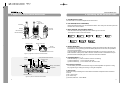
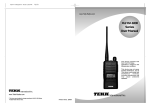
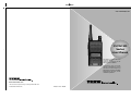
XU/XV-100
Series
User Manual
This device complies with Part
15 of FCC Rules.
Operation is subject to the
following two conditions:
This device may not cause
harmful interference, and 2)
This device must accept any
interference received, including
interference that may cause
undesired operation.
www.Tekk-Radios.com
* This User manual subject to change according to XU/XV-100 Series
Portable Radio without notice.
Printed in Korea. 200808
www.Tekk-Radios.com
Table of Contents
1. Precautions
2. Features
3. Appearance of XU/XV-100 Series Radio
4. Operating XU/XV-100 Series Radio
5. Basic Operation of XU/XV-100 Series Radio
6. Charging the Battery
7. Operating Instructions of XU/XV-100 Series Radio
Thank you for your purchase of the XU/XV-100 Series Radio.
1. When using the Radio, please read the enclosed user guide in details.
2. The functions and specifications are subject to be changed without notice for
improvement of the Radio performance.
Radio
Battery Pack
Antenna
Belt Clip
Adaptor/Charger
User Manual
Components could be changed by buyer request.
1
2
3
4
5
6
8
www.Tekk-Radios.com
2. Features
1. Precautions
Don’t remove the antenna from the Radio or don’t transform the antenna or
don’t make any change on the antenna. The strong electronic wave to be
emitted from the Radio can have an effect on the performance of the Radio and
can cause the Radio to have a defect.
Don’t disassemble or reorganize the Radio. The disassembly or reorganization
will be causes of defect or malfunction and it will be impossible to make repair
afterward. Also, a punishment can be made by law.
The XU/XV-100 Series Radio is developed to be user friendly, compact design and light
weight and to have the similar communication range to the industrial Redio and the Radio is
suitable for leisure and women due to much lighter weight compared with the other Radios.
The followings are the main features of the XU/XV-100 Series Radio.
16 Groups and 128 Channels are selectable.
Call guard Squelch of standardized 53 CTCSS / 208 DCS
Don’t use the other frequency except for the permitted frequency in order not to
be punished by law.
Frequency inverter type of Scramble function
Compander function
Don’t give an excessive shock to the Radio.
Don’t place the Radio where the direct sunlight and/or the high temperature
occurs.
If the Radio is placed for a long time in car in summer, the hot temperature in
the car may cause an explosion of battery.
Sharp substance and/or an excessive shock may cause damage to the battery.
Dual Tone Modulation Frequency (DTMF)
Normal Scan / Priority Scan
VOX
2 Tone / 5 Tone
BCL / BCLO
In case of the area that medical equipments are being used, please use the
Radio after discussion with the equipment maker or the related doctor.
Please don’t use the Radio at the place where computer or other electric /
electronic devices are being used, because the strong electronic wave from the
Radio can have an effect on the equipments.
Please keep the Radio away at least 1inch from the body.
If the outside surface of antenna gets stripped out, it can make a burn on the
skin.
If you contact a conductive metal to battery terminal, a heat can be made and
it may cause fire, explosion and burn. Especially, please be careful when
putting the battery in a pocket or a bag.
When using an earphone, please don’t listen to the sound at a high level.
The high sound may have a bad effect on your ear.
1
Time-Out Timer (TOT)
Monitor
1Watt Speaker Power
PLL synthesizer type
DC+3.7V Li-ion/ 1,800 mAH high capacity Battery
5 step Squelch control using RSSI.
Lone Worker
Remote Radio Stun / Unstun(Use 5 tone)
Cloning function
Pc Programing cable in USB type
2
www.Tekk-Radios.com
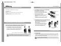
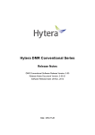
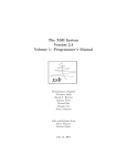
3. Appearance of XU/XV-100 Series Radio
4. Operationg XU/XV-100 Series Radio
1. On/Off/Volume Control
Turns the radio on and off and adjusts audio volume level.
Antenna
On/Off/
Volume control
PTT Button
2. PTT Button(Push-To-Talk Button)
Radio transmission button. It is recommended to talk 5~10cm away from the micro phone for
the best voice communication.
Belt Clip
Accessory
Connector
3. Menu Button(P, Program Menu Button)
Enter into Menu mode by pressing the Menu button (P) for 2 seconds.
The sequence of menu mode is as follows.
Menu Button(P)
Monitor Button(M)
→
→
→
Compander → Change Group →
Down Button (▼)
Enter Button (
Battery Pack
RX/ TX LED
figure 3-1) Appearance of XU/XV-100 Series Radio
Alert
Key Lock
→
→ KEY Sound →
Antenna Connector
On/Off/
Volume control
2 Tone
5 Tone
→
Scramble
→
Squelch
) Up Button (▲)
→
Battery Locker
ID
→
Priority SCAN & Normal SCAN
CTCSS & DCS
VOX
Scramble
→
VOX
→ Lone Worker
4. Monitor Button(M)
The monitor mode is enabled and disabled by pressing the Monitor button (M) on the side.
Normal Mode : During pressing the Monitor button(M) for about 2 seconds, it is possible to
check the receiving status.
Continuous Mode : During pressing the Monitor button(M) for more than 2 seconds, the
Radio will make a “Beep” tone, which means the monitor function is maintained and if you
press the Monitor button(M) again, the monitor function will be released.
5. Channel Buttons( ▼,▲ )
Channel Buttons(▼,
▲) have 2 functions as shown in following.
① Channel buttons(▼,
▲) are to change channels.
② Channel buttons(▼,
▲) are to select menu at menu mode.
6 Accessory Connector
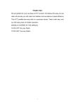
Battery Level Indicator
RSSI
Compander
The Accessory Connector is used when using an external speaker microphone or doing
PC programming or making the Cloning or using as a Repeater.
7. RX /TX Led
Channel & Status
figure 3-2) XU/XV-100 Series LCD Indication
3
This LED is a lamp indicating the current status of the Radio and please refer to the below
contents.
① RX : Green Lamp.
② TX : Red Lamp.
③ CTCSS, DCS Error : Green Blinks.
4
www.Tekk-Radios.com
4. Operationg XU/XV-100 Series Radio
④ Low Battery: Red Blinks with “beep” sound.
5. Basic Operation of XU/XV-100 Series Radio
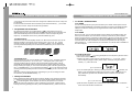
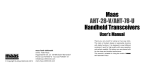
▶ 5.2 Installation and Removal of the Battery
5.2.1 Installation of the battery
8. Speake : 0.8W
9. Mic : It is recommended to talk 5~10cm away from the mic.
To install battery, slide up the battery towards
the top of the radio until battery latch is locked.
10. Battery Locker : This is for separation of battery.
5.2.2 Removing the Battery
Installation of the
Battery
- Slide the battery latch located on the bottom
of radio to the open position as shown in
figure 5-2.
- The battery is removed by pressing it against
and sliding it towards the bottom of the radio.
Removing the Battery
figure 5-2) Installation and
Removal of the Battery
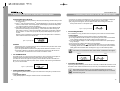
▶ 5.3 Installation and Removal of the Belt Clip
5. Basic Operation of XU/XV-100 Series Radio
Please read this manual carefully before using XU/XV-100 series Radio.
This manual contains important information about using Radio.
- To attach belt clip to radio, align belt clip
rails with the grooves in radio and slide the
belt clip onto the mounting rails until it
latches into place.
- To remove belt clip from radio, push up on
tab of belt clip with flat bladed screwdriver
and at the same time, slide the belt clip
towards the top of Radio(figure 5-3).
▶ 5.1 Installation and Removal of the Antenna
figure 5-3) Installation and Removal of
the Belt Clip
To install the antenna, insert the antenna into antenna
connector and screw the antenna clockwise. To remove
the antenna, screw the antenna counter clockwise.
6. Charging the Battery
figure 5-1) Installation and Removal of the Antenna
When installation of the antenna, giving a strong pressure to the Radio or pulling
the antenna with a strong power from the Radio can make a damage on the
antenna connector, which may cause the Radio to have a critical problem.
▶ 6.1 Safety Notes
1) The radio of XU/XV-100 series receives power from high-performance Li-ion battery
(XSB-1800). XSB-1800 Battery is safe of high performance and highly reliable, and
could be charged very fast. XSB-1800 Battery has been designed suitably only for the
charger of Tekk International Inc (DC-100).
The charging of the enclosed Radio on the other maker’s charger will cause
damage to the battery and the Radio.
5
6
www.Tekk-Radios.com
6. Charging the Battery
7. Operating Instructions of XU/XV-100 Series Radio
2) Please charge the battery before using the radio for best performance and safety.
3) When you charge the battery that is installed in the Radio, please turn off the radio first
to charge the battery.
The continuous rapid discharge (for example, when making a short circuit on
the ‘+, -’ terminals of battery by a metal substance) may make a fatal defect
and the battery can be exploded. Also, it can cause a fire.
4) Using the correct battery will improve the efficiency and safety.
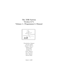
▶ 7.1 Power On/Off
Turn Power switch clockwise. As soon as power is supplied, the backlight will be turned on.
If the user had set up the user ID, it will be displayed on the LCD and radio will enter into
the latest state as a signal sound is generated.
When turning (power) on the radio by pressing a button on it, the radio may
enter into a special modes in which transmission and reception is impossible.
Please don’t turn on the radio by above way.
▶ 6.2 The Time of Charging
Low battery voltage will make the radio have less coverage and also make the
performance worse. Please charge the battery in case of following:
1) When you think performance of the radio becomes lower
2) When the red lamp on RX/ TX Led blinks (every 0.5 second) during transmission or
reception
3) When the battery icon blinks
4) When “beep” sound is generated while the radio is in use.
▶ 6.3 How to Charge
1) Plug the Adaptor for desk charger into the electricity power outlet.
2) When charging the Radio with the battery installed, please turn off the power of the
Radio and place the Radio on the charger (The charger has a slide slot.).
3) After completion of the charging, the green LED on the charger will light. However,
please continue the charging for 30 more minutes for the complete full charge.
status
LED Indication
During charging When charging
Red LED lights
After charging
figure 7-1) User ID
▶ 7.2 Transmission Method
For transmission, press PTT button on the left side of the radio. As soon as the user
presses keys according to the setting, DTMF or 5-tone ID will be transmitted, and during
this time, voice communication will be interrupted for several seconds. Then, red LEDs
for transmission and reception will be turned on. It is recommended to talk 5 ~ 10cm
away from the microphone for the best voice communication.
☞ Note: If the user makes transmission for more than a certain time while BCLO or TOT
feature is on, transmission will be forcefully disconnected for other users.
If present channel is TX Inhibited by pc program, TX will not be worked.
(By PC Program, it could be set.)
Detecting error
Green LED lights Green LED lights Red LED blinks
▶ 6.4 Charger (DC-100)
figure 7-2) When receiving
figure 7-3) When transmitting
The DC-100 charger is designed to charge only the Li-ion battery enclosed in this Radio.
▶ 7.3 Reception Method
Specifications of DC-100 Charger / Adaptor
• INPUT VOLTAGE
: AC100V~240V
• BATTERY
: XSB-1800
• QUICK CHARGING TIME : In 4 and half hours
• OPERATION TEMPERATURE : 0℃~+50℃
• SIZE
: 76(W)x85(D)x37(H)m/m
• Charging Current
: 750mA(Fast charging)
7
The user should not press PTT button during the reception. The user can adjust the
volume by Volume switch, and during reception, the green LED will be turned on.
Depending on conditions of the transmitting radio.
▶ 7.4 Changing Channels
Channel buttons (▼,
▲) are to change channels. Press Up button (▲). Then, “beep”
sound will be generated and the channel number will be increased. Or press Down
button (▼) to decrease the channel. If the user presses Up or Down button while only
8
www.Tekk-Radios.com
7. Operating Instructions of XU/XV-100 Series Radio
one channel is set, the channel will not be changed and a different sound from “beep” will
be generated.
For fast increase or decease channel numbers, press Channel buttons (▼,
▲) for a while.
In this case, however, “beep” sound will not be generated.
▶ 7.5 Operation of Scan function
By pressing Menu Button (P) and Enter Button (
) in order within 0.5 second in
Standby mode, the user can activate Scan function. After Scan function is activated, the
radio will automatically search channels and detect a channel corresponding to the
frequency. To deactivate Scan function, press Menu Button (P) once.
7.5.1 Normal Scan
At the Scan mode, the LCD displays ‘SCAN’ icon. When the scan list is S1, S2, S3, the
Radio proceeds the channel scan in the sequence of S1, S2, S3, S1, S2,.... During
receiving a signal, if you press the UP(▲) or DOWN (▼) button, you can delete the
receiving channel temporarily from the scan list and at that time, you can move to the
next channel.
7. Operating Instructions of XU/XV-100 Series Radio
▶ 7.7 2TONE / 5TONE function
7.7.1 2TONE
You can use the private and group tone functions by the central control system which is
using the 2TONE SIGNALING. If the Radio receives the tone signal, the Radio will make
a Beep sound which is advising the tone signal status and which means the Radio is
ready to talk.
7.7.2 5TONE
At the tone mode, you can make the private & group calls by the 5TONE and each call
memory has the call IDs up to 30 numbers. The set-up of call memory and 5-TONE is
made by PC programming. If pressing the Enter button(
) for 2 seconds at the general
mode, the Radio is converted to the call mode and if pressing the Menu button(P) for
2 seconds at the call mode, the Radio is converted to the general mode. By using the
channel buttons (▼,
▲) at the call mode, the call number of a channel which is available for
the call is displayed.
figure 7-6) General Mode
Channel 1 Channel 2 Channel 3 Channel 4 Channel 5
Channel 8
7.5.2 Priority Scan
At the Priority Scan mode, the LCD displays ‘SCAN’ and ‘P-’ icons. The Radio scans the
channel in the sequence of P, S1, P, S2, P, S3,.... at the priority scan mode. During
receiving signal through the common channel, the Radio scans the priority channel
periodically and if the Radio detects the Priority channel, it starts receiving the channel.
During receiving the signal, you can move to the following scan channel by pressing the
UP(▲) or DOWN button(▼). If you press the Enter button(
), you can erase the current
receiving channel temporarily from the scan list and at that time, you can move to the next
channel.
But in the course of receiving the Priority channel signal, you can not change or erase
the channel by the UP/DOWN buttons(▼,
▲).
figure 7-7) Call Mode
1) 1:1 Call at call mode
Press the Enter button(
) for a long period(about 2 seconds) at the general mode in
order to enter into the call mode.
① Select your party to call by using the channel buttons (▼,
▲). If you ( ID : 12345 )
want to call your party(ID : 54321), select him(ID : 54321) by using the channel
buttons (▼,
▲) at the call mode.
figure 7-8) ID Selection
② You can call the party (ID : 54321) by pressing the Enter button(
) and then, the
Radio of your party(ID:54321) displays the ID number "12345". Even though your
party’s Radio is in general mode, the Radio will be converted to the call mode
automatically.
▶ 7.6 Key Lock function
During pressing the Menu button(P) at the receiving standby mode, press the UP button
(▲) within 0.5 second and then, the Key Lock function will be executed and the key icon
(
) of LCD will appear. At this situation, the other key except for the PTT and the
Monitor key will not be operated. In order to release the Lock function, press the Menu
button(P) and during pressing the button, press the DOWN button(▼) within 0.5 second.
9
figure 7-9) ID Transmission
③ After the call is completed, the Transmission and the Reception have no restriction,
which means that the RX/TX will be free.
10
www.Tekk-Radios.com
7. Operating Instructions of XU/XV-100 Series Radio
2) Group(1:N) Call at call mode
① In order to make the Group call at the call mode, the following should be set up at the
PC programming.
② If the 1st party (ID:53579) and the 2nd party(ID:52468) are in one group, the "5AAAA"
which is a call number / call name(example : baseball player) should be designated.
("A" means that all the numbers are applied.)
③ If the caller makes a call to the group of baseball players, the caller’s Radio should
press the Menu Button(P) and Up button (▲) at the same time after selecting the
party with ID "1AAAA". In this case, the Radios of the party1 and the party 2 display
the ID "1AAAA". In case of the group call, the party’s Radio displays the group ID
number.
After the call is completed, the Transmission and the Reception have no restriction,
which means that the RX/TX will be free.
figure 7-10) Group Call
3) RESET
This Reset function converts the RX/TX with no restriction to the previous Close mode.
the Monitor button (M) at the call mode.
① The call signal will be transmitted to the party’s Radio with the ID number “C” tone.
② If the party’s Radio is in the Close channel and after receiving the call with the “C”
tone, the call is converted to the “RX/TX with no restriction” mode.
▶ 7.8 STUN function
7. Operating Instructions of XU/XV-100 Series Radio
① Press the “P” button of the Radio to turn on. Then, the -Prog- message is displayed.
② Connect the Programming cable to the Ear/Microphone Jack of Radio.
③ By using the PC Program, store the data and after disconnecting the cable, turn
off the power and turn on the power again.
figure 7-12) Program Screen
▶ 7.10 Cloning function
The CLONING is to copy the data such as Frequency/Tone/Scan into the other Radio.
* Cloning Method
① First, please prepare the Cloning cable for XU/XV-100 Series Radio.
② The original Radio should be turned on with pressing the PTT button and the Radio
to be copied should be turned on with pressing the Menu button(P) .
③ The original Radio displays -CLON- message, and the Radio to be copied displays
Prog- message.
④ Connect the Clon cable to the Ear/Mic Jack of 2 Radios.
⑤ If pressing the Enter button(
) of the original Radio, the copy is made and after
completing, please disconnect the cable and turn off & on the power of the 2 Radios.
Finally please use the Radio after checking if the copy is made without problem.
If the Cloning is made into the other maker’s Radio, a malfunction can happen.
copy
original
The Radio is lost or in case you don’t want someone to use your Radio, the reception of
STUN ID saved in the Radio protects the Radio from the use by someone.
(The Stun ID can be set up by PC Program.) If the STUN ID is saved in the Radio, the
Radio can’t be used even after the power off & on of Radio. After receiving the UNSTUN
ID, you can use the Radio.
figure 7-13) CLON Screen
▶ 7.11 Menu description
figure 7-11) STUN Screen
▶ 7.9 Programming function
The Programming is the function for input of the data such as Frequency/Tone/Scan into
the Radio.
* Programming Method
First, please prepare the Program cable for XU/XV-100 Series Radio.
11
If pressing the Menu button(P) on the side for 2 seconds, the Radio will be in Menu mode.
The Menu mode consists of 9 Menus and you can use your desired Menu after selection.
After entering into the Menu, if you don’t operate the Menu for more than
8 seconds, the Menu mode will be terminated automatically and it is converted
to the Receiving mode.
12
www.Tekk-Radios.com
7. Operating Instructions of XU/XV-100 Series Radio
7. Operating Instructions of XU/XV-100 Series Radio
7.11.1 Compander selection
displayed on your Radio to use your Radio in convenience and efficiently.
This Compander selection is for On( )/Off( ) of the Compander.
The selection can be made by the PC program and at the Menu.
① Enter into the Menu mode.
② By using the channel buttons (▼,
▲), choose the "Comp" and press the Enter button
(
).
① Choose the "Id ANI" by the channel buttons (▼,
▲) and press the Enter button(
③ By using the channel buttons (▼,
▲), choose the ON( ) or the OFF( ) and press the
Enter button(
) to store.
④ In order to come out of the Menu mode, press the Menu button(P) and by selecting the
On( )/Off( ), the Compander ICON(
) on LCD appears/disappears.
② After the “d-TON” message comes out, choose the ON(
buttons (▼,
▲) and press the Enter button(
).
)/OFF(
) by the channel
③ After the “C-TON” message comes out, choose the ON(
buttons (▼,
▲) and press the Enter button(
).
)/OFF(
) by the channel
④ Comes out of the Menu mode by pressing the Menu button(P).
7.11.2 Group change
The Radio is designed to have total 512 Channels and 16 Groups and the selection of
each Group & Channel can be available by PC program and Menu.
① Enter into the Menu mode.
② By using the channel buttons (▼,
▲), choose the "Group" and press the Enter button
(
).
③ Using the channel buttons (▼,
▲), choose the Group and press the Enter button(
to store.
).
7.11.4 Scramble selection
The Scramble is for protection from overhearing and the scramble reverses the voice signal
from microphone to a specific frequency and a mixed voice in order for the other person not
to hear your voice.
The selection can be available by PC program and Menu.
① Enter into Menu mode.
② Select “SCrA” by pressing Channel buttons (▼,
▲), and press Enter button(
).
)
③ Select On(
) or Off(
) by pressing Channel buttons (▼,
▲), and save the selected
status by pressing Enter button(
).
④ In order to come out of the Menu mode, press the Menu button(P).
7.11.3 ID output
This is for transmission of your ID and reception of your party’s ID. ID is divided by DTMF
and Call ID. Especially the Call ID transmits your ID to the party and also, the party’s ID is
13
④ Exit Menu mode by pressing Menu Button(P) button. Select Off(
symbol will disappear on the LCD.
). Then, the “ SCR”
14
www.Tekk-Radios.com
7. Operating Instructions of XU/XV-100 Series Radio
7. Operating Instructions of XU/XV-100 Series Radio
By PC Program and menu, it could be set.
① Enter into Menu mode.
② Select “H-FrEE” by pressing Channel buttons (▼,
▲), and press Enter button(
7.11.5 Set Squelch
Squelch sensitivity level is selectable by 5 step.
By PC Program and menu, it could be set.
① Enter into Menu mode.
② Select “SQUELCH” by pressing Channel buttons (▼,
▲), and press Enter button(
Then, the message of the squelch sensitivity will be displayed.
).
).
③ Select On(
(
).
) or Off(
) by pressing Channel buttons (▼,
▲), and press Enter button
③ Select squelch sensitivity -0~5- by pressing Channel buttons (▼,
▲), and press Enter
button(
) to save the level
④ Select on(
). Then, the “vox , H-Fr 05” symbol s will appear on the LCD.
Set sensitivity by pressing Channel buttons (▼,
▲), and press Enter button(
).
④ Exit Menu mode by pressing Menu Button(P).
7.11.6 Set KEY Sound
Set Key Sound menu is to decide whether to generate sound or not when the user presses
four buttons . (▼, ▲,
,
P)
By PC Program and menu, it could be set.
① Enter into Menu mode.
② Select “Sound” by pressing Channel buttons (▼,
▲), and press Enter button(
).
⑤ Select Off(
). Then, the “vox” symbol will disappear on the LCD.
⑥ Exit Menu mode by pressing Menu Button(P) button.
7.11.8 Set Lone Worker
The Set Lone Worker is for transmission of emergency alarm sound without pressing the
designated button within a period of time when night patrol or guarding and the Lone
Worker can be set to be ON(
)/OFF(
).
The selection can be available by PC program and Menu.
① Enter into Menu mode.
② Select “LONE W” by pressing Channel buttons (▼,
▲), and press Enter button(
).
③ Select On( ) or Off( ) by pressing Channel buttons (▼,
▲), and save the selected
status by pressing Enter button(
).
③ Select On( ) or Off( ) by pressing Channel buttons (▼,
▲), and save the selected
status by pressing Enter button(
).
④ Exit Menu mode by pressing Menu Button(P) button. Select Off(
symbol will disappear on the LCD.
). Then, the(
)
7.11.7 Set VOX
Set VOX is to enable users to make transmission for VOX without pressing PTT button.
(This function could be available with Ear Mic [External VOX]).
15
④ Exit Menu mode by pressing Menu Button(P) button.
16