1
LVDT/A & LVDT/D
Amplifier / Signal Conditioner
User Manual
www.mantracourt.co.uk
LVDT/A & LVDT/D Manual
Contents
Chapter 1 The LVDT Conditioner..................................................................................................... 1
Chapter 2 Installing the LVDT/A & LVDT/D......................................................................................... 2
Terminal Connection ..................................................................................................................... 3
Dimensions of the Enclosure and Mounting Holes ................................................................................... 3
Chapter 3 Analogue Outputs .......................................................................................................... 4
Output Connections ...................................................................................................................... 4
Output Current Mode Settings – Jumpers JP1 & JP2................................................................................ 5
Chapter 4 Input Calibration ........................................................................................................... 6
Span (gain) - SW1 (0 = OFF 1 = ON) .................................................................................................. 6
Zero (offset) - SW2 ....................................................................................................................... 7
The LVDT/A & LVDT/D Filter ........................................................................................................... 7
Filter Cut off - SW3 (0 = OFF 1 = ON) ............................................................................................... 7
Chapter 5 Specification for LVDT/A & LVDT/D .................................................................................... 8
W A R R A N T Y ........................................................................................................................... 9
Chapter 1 The LVDT Conditioner
The LVDT provides a wide range of signal conditioning for LVDT transducers.
Offered in two versions, the LVDT/A for 110/240V AC or 18-24V DC operation and the LVDT/D which is DC powered
only.
Transducer sensitivities between 20mV and 10V are accommodated by a combination of DIL switch settings and a
fine trim potentiometer.
Similar arrangements are provided for any ‘zero’ errors in the transducers and can be used to offset the readings by
up to ±35% of full scale.
A wide frequency response is offered, of typically DC to 200Hz. There is an on-board low pass filter, which can be
switched in to reduce high frequency fluctuations or induced electrical noise, to give stable readings under adverse
conditions.
A wide range of output options for current, and uni-polar or bi-polar voltage can be configured by DIL switch
settings.
Both the AC and DC versions are based on a common board and are mounted in a light grey ABS case sealed to IP65
standard.
1
Mantracourt Electronics Limited LVDT/A & LVDT/D User Manual
Chapter 2 Installing the LVDT/A & LVDT/D
In order to maintain compliance with the EMC Directive 2004/108/EC the following installation recommendations
should be followed.
Inputs:
Use individually screened twisted multipair cable. (e.g. FE 585 - 646)
The pairs should be :
pins 1 & 6
pins 2 & 5
pins 3 & 4
Terminate all screens at pin 1 of the input. The screens should not be
connected at the transducer end of the cables.
Comms Port:
Use individually screened twisted multipair cable. (e.g. FE 118-2117)
The pairs should be:
-Tx & +Tx
-Rx & +Rx
Terminate screens at pin 1 of the input .
The screens should not be connected at the host port.
Analogue
Output:
Use screened twisted pair cable. (e.g. RS 626-4761)
Terminate screen at pin 1 of the input.
The screen should not be connected at the host port.
Pin 1 of the input should be connected to a good Earth. The Earth connection
should have a cross-sectional area sufficient enough to ensure a low
impedance, in order to attenuate RF interference.
Country
UK
Supplier
Farnell
Part No
118-2117
UK
Farnell
585-646
UK
RS
626-4761
Description
Individually shielded twisted multipair cable (7/0.25mm)- 2 pair
Tinned copper drain. Individually shielded in polyester tape.
Diameter: 4.1mm
Capacitance/m: core to core 115 pF & core to shield 203 pF
Individually shielded twisted multipair cable (7/0.25mm)- 3 pair
Tinned copper drain. Individually shielded in polyester tape.
Diameter: 8.1mm
Capacitance/m: core to core 98 pF & core to shield 180 pF
Braided shielded twisted multipair cable (7/0.2mm)- 1 pair
Miniature- twin -round Diameter: 5.2 mm
Capacitance/m: core to core 230 pF & core to shield 215 pF
Mantracourt Electronics Limited LVDT/A & LVDT/D User Manual
2
UNPACKING
Carefully remove the LVDT unit from its packing. Check that the unit is complete and undamaged.
The LVDT/A & LVDT/D units can operated in any industrial environment providing the following limits are not
exceeded
Operating
temperature
Humidity
Storage temperature
-10ºC to +50ºC
95% non condensing
-20ºC to +70ºC
Two power supply options are available
LVDT/A:
220/230VAC, 50/60Hz
110/120VAC, 50/60Hz
5W Max.
LVDT/A & LVDT/D:
18-24V DC, 5W (approx. 150mA fully loaded)
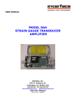
Terminal Connection
On the surface mounted versions, connections to the LVDT/A & LVDT/D input/output signal and the power supply
are made via 2.5mm² field terminal blocks.
Cable entry in the cased versions is via glands in the side of the case.
Dimensions of the Enclosure and Mounting Holes
3
Mantracourt Electronics Limited LVDT/A & LVDT/D User Manual
Chapter 3 Analogue Outputs
Two analogue outputs are available from the LVDT, DC current and DC voltage. The ranges offered are as follows:Output
DC voltage
Range
±10V
±5V
0 - 10V
0 - 5V
DC current
0 - 20mA
4 - 20m
NB:
Maximum Load on voltage ranges is 2mA. Bi-polar input, -F.S.
to +F.S.
NB:
Maximum impedance 500R. Uni-polar input, zero to +F.S.
The analogue output options are summarised below,
NB. Full scale output for the voltage ranges is achieved with a bi-polar ( ± ) input.
Output Connections
In ‘Sink’ mode the +ve end of the load is connected to the internal +15V supply on the LVDT and the -ve end is
connected to the LVDT output. The current through the load is ‘sunk’ by the LVDT towards ground (0V).
N.B. In this mode neither connection to the output load is electrically common to the load cell.
Select this option by fitting the two jumpers in the positions next to the span trimmer (See Output Current Mode
Settings – Jumpers JP1 & JP2)
In ‘Source’ mode the +ve end of the load is connected to the LVDT output and the current is ‘sourced’ by the LVDT
output through the load towards ground (0V).
This mode has the advantage that the negative output connection is common to the load cell
‘- Excitation’ terminal.
Select this option by fitting the two jumpers in the positions furthest from the span trimmer (See Output Current
Mode Settings – Jumpers JP1 & JP2)
Mantracourt Electronics Limited LVDT/A & LVDT/D User Manual
4
Output Current Mode Settings – Jumpers JP1 & JP2
Switch Settings (0 = Off
1 = On
x = Don't care) :-
Analogue Output Options - SW4
SW4
± 10V
± 5V
0-10V
0-5V
0-20mA
4-20mA
1
0
0
0
1
x
x
2
0
1
1
1
x
x
3
0
0
1
1
x
x
LVDT Excitation Frequency - SW4 (0 = OFF 1 = ON)
6
1
0
1
1
0
5
7
0
1
1
0
1
8
0
0
0
1
1
1kHz
2kHz
3kHz
4kHz
5kHz
Mantracourt Electronics Limited LVDT/A & LVDT/D User Manual
4
x
x
x
x
0
1
5
x
x
x
x
0
1
Chapter 4 Input Calibration
The LVDT/A & LVDT/D provides the excitation and signal conditioning to cater for a wide range of LVDT
transducers.
Select the analogue output range as detailed in 'Chapter 3' by means of SW4.
Span (gain) - SW1 (0 = OFF 1 = ON)
1
0
1
0
0
0
0
0
0
0
2
0
0
1
0
0
1
0
0
1
3
0
0
0
0
1
0
0
1
0
4
0
0
0
0
0
0
0
0
0
5
1
1
1
0
0
0
0
0
0
6
0
0
0
1
1
0
1
1
0
7
0
0
0
0
0
0
1
1
1
8
1
1
1
1
1
1
0
0
0
20mV
50mV
100mV
200mV
500mV
1V
2V
5V
10V
Potentiometer P1, provides fine trimming and range overlap to enable the LVDT/A & LVDT/D to be calibrated
precisely to any given value within its ranges.
SW1 sensitivity settings shown in the table are for a Full Scale Output e.g. 0-10volts.
The LVDT/A & LVDT/D can be calibrated with the transducer connected, provided that two calibration points can be
implemented. e.g. by applying known displacements.
Actual calibration is carried out in the following way:1. Set the correct switch settings on SW1 using the transducer's calibration sheet supplied by the manufacturer ( see
table Chapter 4 Page 1) . This is normally specified as sensitivity or full range output, and should be in mV or
Volts.
2. Apply the known low calibration displacement (this may be zero if required), and note the analogue output,
having ensured that the SW1 settings are correct for the transducer sensitivity as 1.
3. Apply the known high calibration displacement and note the analogue output. (For optimum accuracy this should
be at least 80% of full scale)
4. Use the fine trim control, P1, to obtain the required change in volts or mA, between the two calibration points.
e.g.
• Required output at low calibration point = 0V
• Required output at high calibration point = 7.5V
i.e.
• A difference of 7.5 volts is required between the calibration points. If the actual reading at the low calibration
point is say, 0.5 Volts, then trim the high point to 8.0 volts, to achieve a difference of 7.5 volts.
Note: It may be necessary to repeat these steps, until the required change in output is
achieved.
5. Use the fine offset control, P2 in conjunction with the coarse switches SW2/3 -5 to set the output to the
required absolute values. Each switch within SW2, offsets the output by a particular amount, shown as a % of full
scale in the following table.
Mantracourt Electronics Limited LVDT/A & LVDT/D User Manual
6
Zero (offset) - SW2
SW2
Offset
Note:
1
+ve
2
-ve
3
20%
4
10%
5
5%
6
x
7
x
8
x
SW2/1 & /2 Should not both be on.
Use switches 3 - 5 in conjunction with the polarity switches 1 and 2, to get as close as possible to the required
offset value.
Use the fine control P2 to achieve the final setting.
If more than one switch is on at a time, then the output of each is summed to give an overall offset to the output,
which can be up to ±35% of full value.
This offset adjustment can be used either to compensate for the transducer offset error or to introduce a shift into
the output's working range.
Excitation Amplitude - SW2/8
Normally off.
Switching SW2/8 on reduces the excitation by a factor of two. This allows lower impedance transducers to be used
without overloading the electronics.
Please note that it may be necessary to alter the setting of the Span switch, SW1 to compensate for the resulting
lower input signal.
The LVDT/A & LVDT/D Filter
The LVDT/A & LVDT/D incorporates a second order low pass filter which can be switched in to improve performance
in electrically noisy environments. It can also be used to reduce the effects of high frequency fluctuations in the
displacement.
The cut-off frequency of the filter is set by the 8 way DIL switch SW3 as shown in the following table:-
Filter Cut off - SW3 (0 = OFF 1 = ON)
SW3
5Hz
10Hz
15Hz
20Hz
50Hz
100Hz
150Hz
200Hz
7
1
0
1
0
1
0
1
0
1
2
0
0
1
1
0
0
1
1
3
0
0
1
1
0
0
1
1
4
0
1
0
1
0
1
0
1
5
1
1
1
1
0
0
0
0
6
1
1
1
1
0
0
0
0
Mantracourt Electronics Limited LVDT/A & LVDT/D User Manual
7
x
x
x
x
x
x
x
x
8
x
x
x
x
x
x
x
x
Chapter 5 Specification for LVDT/A & LVDT/D
Parameter
Power supply ac LVDT-A only (110/230 Vac) 50-60Hz
Power supply dc: LVDT-A and -D
Power supply current dc: (depends on loading)
Excitation
LVDT Frequency (Selected by Switch 1,2,3,4,5 kHz)
LVDT Impedance
LVDT Sensitivity (switchable)
Gain adjustment (Pot - fine adj)
Offset adjustment (Pot - fine adj)
Offset adjustment (Switchable - coarse adj)
Output load (voltage output)
Output load (current output)
Bandwidth (No filter) 3 dB point
Filter cut-off (switchable ranges)
Output ripple 200Hz filter (1kHz excitation)
Output ripple 50Hz filter (1kHz excitation)
Zero temperature coefficient
Span temperature coefficient
Linearity
Gain stability - 1st 1000 hours
Gain stability - 2nd 1000 hours
90 day offset stability
Output load stability gain (0 - 100%)
Output load stability offset (0 - 100%)
Power supply rejection gain (0 - 100%)
Power supply rejection offset (0 - 100%)
Operating temperature range
Storage temperature range
Humidity
Noise (1kHz / 20Hz filter / dc powered)
Min
99/198
18
138
1
50
0.02
0
0
DC
5
0
-20
-
Typical
110/230
24
145
4.5
200
0.3
0.05
2
0.01
0.05
0.2
0.1
6
3
Max
126/253
28
150
5
10
25
10
30
2
500
200
200
4
0.015
0.1
0.4
0.2
10
0.01
0.01
0.05
0.05
50
70
95
7
Unit
V ac
V dc
mA (200R)
V rms (SW2/8 OFF)
kHz ±20% Ohms
V
% FSD
% FSD
% FSD
mA
Ohms
Hz
Hz
% FSD
% FSD
µV/ºC
%/ ºC
% FSD
% FSD
% FSD
µV
% FSD
% FSD
% FSD
% FSD
ºC
ºC
%
mV p-p
Output options:
±10V, ±5V, 0-10V, 0-5V, 0-20mA, 4-20mA
Connections:
Field screw terminals - 2.5mm² rising clamp.
Enclosure:
ABS case 160 x 80 x 55 sealed to IP65 fitted with 3 off cable glands.
Controls:
Gain pot
Offset pot
Coarse gain switches
Coarse offset switches
Filter cut-off switches
Output mode switch
CE Approvals
European EMC Directive
2004/108/EC
BS EN 61326-1:2006
BS EN 61326-2-3:2006
Low Voltage Directive
2006/95/EC
BS EN 61010-1:2001
Rated for Basic Insulation
Normal Condition
Pollution Degree 2
Permanently Connected
Insulation Category lll
Mantracourt Electronics Limited LVDT/A & LVDT/D User Manual
8
WARRANTY
All LVDT products from Mantracourt Electronics Ltd., ('Mantracourt') are warranted against defective material and workmanship for a period of
(3) three years from the date of dispatch.
If the 'Mantracourt' product you purchase appears to have a defect in material or workmanship or fails during normal use within the period,
please contact your Distributor, who will assist you in resolving the problem. If it is necessary to return the product to 'Mantracourt' please
include a note stating name, company, address, phone number and a detailed description of the problem. Also, please indicate if it is a
warranty repair.
The sender is responsible for shipping charges, freight insurance and proper packaging to prevent breakage in transit.
'Mantracourt' warranty does not apply to defects resulting from action of the buyer such as mishandling, improper interfacing, operation outside
of design limits, improper repair or unauthorised modification.
No other warranties are expressed or implied. 'Mantracourt' specifically disclaims any implied warranties of merchantability or fitness for a
specific purpose. The remedies outlined above are the buyer’s only remedies. 'Mantracourt' will not be liable for direct, indirect, special,
incidental or consequential damages whether based on the contract, tort or other legal theory.
Any corrective maintenance required after the warranty period should be performed by 'Mantracourt' approved personnel only.
ISO 9001
REGISTERED FIRM
In the interests of continued product development, Mantracourt Electronics Limited reserves the right to alter product specifications without
prior notice.
C
Code No. 517-152
9
Issue 1.7
Mantracourt Electronics Limited LVDT/A & LVDT/D User Manual
12.04.201 1