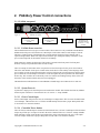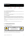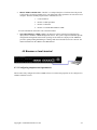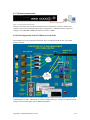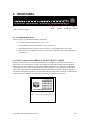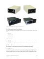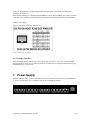
1
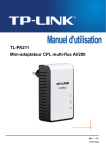
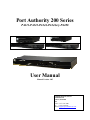
Port Authority 200 Series PA211-PA222-PA244-PA244x/y-PA288 User Manual Manual Version 1.05 Communication Devices Inc. 85 Fulton Street Boonton, NJ 07005 USA Phone: +1 973 334-1980 Fax: +1 973 334-0545 Internet: [email protected] Warranties, Disclaimers and Restriction A.1 Copyright Notice This equipment, all software, firmware and the entire contents of this manual are the copyright property of Communication Devices Inc., Boonton, NJ 07005 USA with all rights reserved. The information contained in this manual is considered proprietary to Communication Devices Inc. and is intended for the exclusive of the original purchaser of the equipment. A.2 Warranty Communication Devices Inc. Warranties to the original purchaser that these devices are free from defects in material or faulty workmanship, in normal use for a period of one (1) year from the date of purchase. one (1) year of the original purchase is determined by Communication Devices Inc. to be defective. All warranty repairs will be made at Communication Devices Inc. Main factory in Boonton, NJ 07005. A.3 Disclaimer While extreme care has been taken in the preparation of the design, software, firmware, hardware and documentation, Communication Devices Inc accepts no liability. For loss of profits or any other incidental, special or consequential damage suffered by the purchaser, even if Communication Devices Inc. has been advised of the possibility of such damages, nor for the claim against the purchaser by any other party. This warranty is limited to repair or replacement at the option of Communication Devices Inc., of any defective part or component which within Copyright © Communication Devices Inc ii Table of Contents 1. PORT AUTHORITY 200 SERIES OVERVIEW........................................................................... 1-1 1.1 PORT AUTHORITY PA211, PA222, PA244, PA244X/Y, PA288 ................................................... 1-1 1.2 FIVE PA200 CONFIGURATIONS. .................................................................................................... 1-2 1.3 FIGURE 5 PA288......................................................................................................................... 1-2 1.3............................................................................................................................................................ 1-3 1.4 COMMON CONNECTIONS .............................................................................................................. 1-3 2. PA244X/Y POWER CONTROL CONNECTIONS....................................................................... 2-4 2.1.1 2.1.2 3. POWERING UP THE DEVICE ...................................................................................................... 3-5 3.1.1 3.1.2 4. PA244x rear panel............................................................................................................... 2-4 PA244 Front Panel.............................................................................................................. 2-5 Connecting Power to Device. .............................................................................................. 3-5 Power on and Self Test ........................................................................................................ 3-6 CONFIGURING THE DEVICE...................................................................................................... 4-6 4.1 THERE ARE 3 WAYS TO CONFIGURE A PA200 ............................................................................... 4-6 4.2 BROWSER OR LOCAL TERMINAL ................................................................................................... 4-7 4.2.1 Configuring simple network parameters ............................................................................. 4-7 4.2.2 Programming Network Properties in PA200 devices via Browser ..................................... 4-8 4.2.3 Using the Serial Console Port to configure IP address. ..................................................... 4-9 4.2.4 Connecting the PA200 to the computer for FEL or OBM loading.................................... 4-10 4.2.5 Network Interface .............................................................................................................. 4-10 4.2.6 Serial Port ......................................................................................................................... 4-10 4.2.7 Modem communication ..................................................................................................... 4-11 4.2.8 Full configuration of the PA-200 device in the field ......................................................... 4-11 5. PORT AUTHORITY –PA200 FRONT PANEL........................................................................... 5-12 5.1 FRONT PANEL ........................................................................................................................ 5-12 5.1.1 LED’s................................................................................................................................. 5-12 RXM LED- Receive Data........................................................................................................... 5-12 DTM LED- Modem Data Terminal Ready ................................................................................ 5-13 RI/CD LED- Ring Indicator and Data Carrier Detect.............................................................. 5-13 6. REAR PANEL ................................................................................................................................. 6-15 6.1.1 Communication Ports ........................................................................................................ 6-15 6.1.2 Host Communication SERIAL Ports (DCE) HOST1 – HOST8 ......................................... 6-15 Cabling for Host Communication Ports............................................................................................ 6-16 6.1.3 Connecting an Output Port to a DCE ............................................................................... 6-16 6.1.4 Power Control Module Ports ............................................................................................ 6-16 6.1.5 Cable connection for Power Modules ............................................................................... 6-17 6.1.6 TELCO Port....................................................................................................................... 6-17 6.1.7 Network Port ..................................................................................................................... 6-17 6.1.8 SERIAL Port ...................................................................................................................... 6-17 6.1.9 Tamper Switches................................................................................................................ 6-18 7. POWER SUPPLY ........................................................................................................................... 7-18 8. ENVIRONMENTAL....................................................................................................................... 8-19 9. INSTALLATION ............................................................................................................................ 9-20 Copyright © Communication Devices Inc III Table of Figures FIGURE 1 PA211......................................................................................................................................... 1-2 FIGURE 2 PA222......................................................................................................................................... 1-2 FIGURE 3 PA244......................................................................................................................................... 1-2 FIGURE 4 PA244X ...................................................................................................................................... 1-2 FIGURE 5 PA288......................................................................................................................................... 1-2 FIGURE 6 - PA244X REAR PANEL .................................................................................................................. 2-4 FIGURE 7 - PA244X FRONT PANEL ............................................................................................................... 2-5 FIGURE 8 USING THE NETWORK INTERFACE ............................................................................................... 4-10 FIGURE 9 USING THE SERIAL INTERFACE .................................................................................................... 4-10 FIGURE 10 USING MODEM COMMUNICATION .............................................................................................. 4-11 FIGURE 11 PA288 FRONT PANEL ............................................................................................................... 5-12 FIGURE 12 PA200 LED’S ........................................................................................................................... 5-12 FIGURE 13 PA200 LED'S ........................................................................................................................... 5-13 FIGURE 14 PA288 REAR PANEL .................................................................................................................. 6-15 FIGURE 15 RJ45 SOCKET CONNECTOR PINOUT .......................................................................................... 6-15 FIGURE 16 DB9 ADAPTER .......................................................................................................................... 6-16 FIGURE 17 PCM 6-10 AMP TOP ROW, PCM 16-20 AMP BOTTOM ROW..................................................... 6-17 FIGURE 18 PCM PINOUT............................................................................................................................. 6-17 FIGURE 19 SERIAL HOST PORT PINOUT........................................................................................................ 6-18 THERE ARE NO DEFAULT USER CREDENTIALS SHIPPED IN THE DEVICE. IT NEEDS TO BE CONFIGURED VIA THE CDI “OUT OF BAND MANAGER” (OBM) TO OPERATE Copyright © Communication Devices Inc IV 1. Port Authority 200 Series Overview 1.1 Port Authority PA211, PA222, PA244, PA244x/y, PA288 The Port Authority 200 series are a Secure 1, 2, 4, or 8 port switches that provide network, dial-up, or Cellular Data access to serial console ports on routers, firewalls, and other network appliances. The devices also provide power control of up to nine (8) remote devices. This table describes the differences between the hardware. All devices run on the same software. Device Network Port # Serial Ports # Power Ports Chassis Dimensions PA211 NO 1 1 External Table Top 3.5”x5.5”1” PA222 YES 2 2 External Table Top 5.5”x6.5”x1.5” PA244 YES 4 4 External Rack Mount 7”x19”x1.5” PA244x/y YES 4 4 Built In 10 AMP Rack Mount 7”x19”x1.5” PA288 YES 8 8 External Rack Mount 7”x19”x1.5” Table 1 Matrix of PA200 Series product configurations PA244x Power Ports 110 VAC with an aggregate 20 AMP maximum. PA244y Power Ports 240VAC with an aggregate 16 AMP maximum. All devices support one to several external CDI power control modules. These power control modules allow remote power reboot of connected devices and can handles up to 20Amps. The PA244x is based on the PA244 but has four build in Power Control Outlets which can control up to 10amps each. PCM 220VAC-6AMP 110VAC-10AMP PCM 240VAC-16AMP 110VAC-20AMP For the purposes of this manual we will only refer to the eight port version the Port Authority 288. All things that apply to the PA-288 apply to the others, except the PA211 which does not offer the network port or it’s capabilities. The PA200 series is designed for the commercial environment that requires strict security without the overhead of government validation like out flagship PA100 FIPS 140-2 validated series. All devices support on board authentication of the RSA SecurID token without a network connection and are PCI compliant. THERE ARE NO DEFAULT USER CREDENTIALS SHIPPED IN THE DEVICE. IT NEEDS TO BE CONFIGURED VIA THE CDI OUT OF BAND MANAGER TO OPERATE Copyright © Communication Devices Inc 1-1 1.2 Five PA200 configurations. The PA211 single port desktop unit Figure 1 PA211 The PA222 two port desktop unit Figure 2 PA222 The PA244 Four port rack mount unit Figure 3 PA244 The PA244x/y Four port and four power controlled power outlets, rack mount unit. Figure 4 PA244x The PA288 Eight port rack mount unit 1.3 Figure 5 PA288 Copyright © Communication Devices Inc 1-2 1.4 Common Connections 4 3 1 2 (1) An RJ45 connector for a Network Connection. This is a 10/100M interface and is labeled NETWORK. There is a BROWSER function that allows simple network properties to be loaded. Default Address is 199.199.199.1 (2) An RJ11 connector for an analog TELCO connection to an internal Modem. This is labeled TELCO. (3) 1 to 8 RJ45 connector(s) for connection to HOST console ports. These are labeled HOST1 through HOST8. The defaults are 9600 baud, 8 data no parity. The ports are pinned out to connect directly to any CISCO console port with a straight RJ45-RJ45 cable. CDI provides RJ45-DB9 adapters for connection to other types of interfaces. (4) 1 to 8 RJ12 connector(s) for connection to CDI Power Control Modules. These are labeled PCM1 through PCM9. These are TTL control ports. CDI provides straight RJ11-RJ11 Telco cables to connect these ports to CDI power control modules. Copyright © Communication Devices Inc 1-3 2. PA244x/y Power Control connections 2.1.1 PA244x rear panel Figure 6 - PA244x rear panel Input for Power Control 115/230vac~20amp 50/60Hz Controlled Power Out 115/230vac 10amp 50/60Hz Master Module System Power In for Master Module 115/230vac .2~.1amp 50/60Hz 2.1.1.1 PA244x Power overview The PA244 has built in four (4) power control outlets. These outlets are relay controlled from the Master Module and switch power from the Power Control Input. Each outlet cannot exceed 10amps of current. The Power Control portion of the PA244x has a separate 20amp C20 Power input connector with a separate 20amp breaker. While each output outlet can draw up to 10amps the totality of the draw on the power control input side of the PA244x cannot exceed 20amps. Each Outlet has a 10amp circuit breaker. This breaker is located on the front panel. The front panel breakers will trip if any individual outlet exceeds 10 amps. There is a 20amp circuit breaker on the rear panel next to the Power Input for the power control outlets. This is the main breaker for the power control outlets on the device. If the totality of the amperage on the power outlets exceeds 20 amps then this breaker will trip. If this breaker trips then the entire load of all the power outlets has exceed 20amps. The breakers on the front panel may not trip and have the main 20amp breaker trip. This would be due to the totality of devices connected exceeding 20 amps. If this is the case then some of the connected outlets may need to be unplugged. CDI manufactures individual Power Control Modules to handle large current draw device in this case. 2.1.1.2 System Power in System Power input powers the microprocessor based master module. This includes the Network, Modem and serial ports in the device. Characteristics are 115~230vac .1~.2amp 50/60Hz. 2.1.1.3 Power Control Input Power Control Input will power the four (4) switched power output outlets. This is a main feed that cannot exceed 20amps. Characteristics are 115-230vac 50/60Hz 20amps. Ensure that a proper 20amp rated cable is used with a C19 connecter attached. 2.1.1.4 Controlled Power Outlets There are four(4) controlled power outlets associated with the one (1) Power Control Input. Each Switched output can provide up to 10 amps of current to the outlet. Characteristics are 115/230vac 10amps 50/60Hz. Each outlet has a 10amp circuit breaker associated with it on the front panel that will “trip” if the output exceeds 10 amps. Ensure that a proper 10amp cable is used with a C14 connector attached. Copyright © Communication Devices Inc 2-4 2.1.2 PA244 Front Panel Figure 7 - PA244x Front Panel MASTER MODULE LED’S PCM ON PCM CIRCUIT BREAKER 2.1.2.1 The PA244x Front Panel Indicators The PA244x has the same front panel indicators for the Master Module but has different indicators for the Power Control Portion of the product 2.1.2.2 PCM LED Each PCM outlet has an LED to indicate that the output relay is “ON” and has voltage directed to it. When an outlet is turned “OFF” the LED will extinguish. 2.1.2.3 Circuit Breaker Each PCM has it’s own circuit breaker. Each output can draw up to 10 AMPs of current. When this threshold is exceeded the output Circuit Breaker will “Trip” and pop out. This indicates the connected load to that outlet has exceeded the 10 amp threshold. The connected load is either too large a device to connect to the output, or the connected load has gone into some type of failure that has caused it to draw too much current. The situation should be corrected BEFORE depressing the Circuit Breaker switch to turn the power back on to that outlet. If the Circuit Breaker continues to “Trip”, the load on that particular outlet needs to be lowered. 3. Powering Up the device 3.1.1 Connecting Power to Device. CAUTION! THIS DEVICE SHOULD BE INSTALLED BY A QUALIFIED SERVICE PERSON AND MUST BE CONNECTED TO AN EARTHED MAINS SOCKET-OUTLET The device will connect to a standard alternating current (AC) wall outlet (110VAC, .15A ~ 240VAC, .075A 50/60Hz). The socket outlet should be installed near the equipment and should be easily accessible. Make sure the power cord supplied is of the correct type for the country being installed. Copyright © Communication Devices Inc 3-5 The user is to disconnect all telecommunication network connectors before disconnecting the power supply cord. In addition the equipment should be installed by a qualified service person and connected to a socketoutlet with a protective earthing contact. In English: equipment must be connected to an earthed mains socket-outlet. In Finland: Laite on liitettava suojakosketinpistorasiaan. In Norway: Apparatet ma tilkoples jordet stikkontakt. In Sweden: Apparaten skall anslutas till jordat uttag. In French: L'utilisateur est de débrancher tous les connecteurs de réseaux de télécommunications avant de débrancher le cordon d'alimentation. En outre, l'équipement doit être installé par un technicien qualifié et connecté à une prise de courant avec un contact de terre . The power parameters are: Voltage 110VAC 240VAC Frequency 60Hz 50Hz Current .2amp .1amp 3.1.2 Power on and Self Test The PA200 will go through an automatic internal self test upon initial power up. If any of the self tests fail, the device will not continue to operate. The status indicator for the self-test is the Alarm LED ALM- Alarm During initialization the ALM LED will illuminate and then extinguish within 3 seconds. The ALM LED will remain illuminated when there is any internal problem with the Port Authority 111. Such problems may be: o Internal Self Test Failure o Internal program checksum/MAC calculation fault o Internal Modem Self Test Failure o Internal microprocessor fault 4. Configuring the device 4.1 There are 3 ways to configure a PA200 There are three ways to configure your PA200 device 1. BROWSER: This interface allows for programming of network parameters only. All other configuration is done through the FEL or OBM. The default address for the network interface is 199.199.199.1. The browser interface will allow you to program network parameters into the device but will not store them on the connected computer. Copyright © Communication Devices Inc 4-6 2. FRONT END LOADER “FEL”: The FEL is a CDI provided piece of software that will provide a GUI interface for storing parameters for your deployment. These parameters are stored in a local computer. The FEL can then program local or remote devices via, 1. Local Serial Port 2. Remote via dial up modem 3. Remote via Network 4. Remote via Cellular Data Modem “CDM” For more information on the FEL refer to the FEL manual. 3. Out of Band Manager “OBM”: OBM is an enterprise software solution for managing large deployments of CDI Out of Band Management devices. The system is SQL based and can provide configuration management and real time reporting for all CDI devices deployed. The OBM also provides a patent pending SSH manager to manage and control all SSH session on a network. For further information on the OBM see the OBM manual. 4.2 Browser or local terminal 4.2.1 Configuring simple network parameters The PA-200 is fully configured via FEL or OBM software. Local network properties can be configured via a dumb terminal or browser. Copyright © Communication Devices Inc 4-7 4.2.2 Programming Network Properties in PA200 devices via Browser PA200 devices are shipped with a default IP address of 199.199.199.1. There are two new simple ways to insert a valid IP address for your network into the device, using a Web Browser, or using a serial connection from your PC to the Serial Console port on the PA1X. In order for these 2 features to be available, one of two things must be true: 1. The device needs to be at the default IP address of 199.199.199.1. OR 2. There must be no users programmed into the device. *** Once the device is off the default IP address AND has at least one user programmed, this feature will be unavailable unless the address is changed back to default or all users are cleared. If the device is at the default IP address of 199.199.199.1 and you plan on using a web browser to configure a valid IP address, you first must temporarily change the IP address of the PC to something in the 199.199.199.XXX subnet. Then you can open a web browser and type in 199.199.199.1 in the address bar. You will see this window if you connect to the PA1X device: You will see the firmware version in the device and its serial number. From this page you can enter these parameters: Copyright © Communication Devices Inc 4-8 The OBM (Out of Band Manager) is the CDI software for managing CDI devices. OBM IP Address and OBM Port Number fields can be disregarded if using DDM. After hitting the “Submit New Settings” button you will be able to connect to the device at the newly assigned address. 4.2.3 Using the Serial Console Port to configure IP address. If you have an available serial port on your PC you can use the provided CDI adaptor and cable to connect directly to one of the serial host ports on the back of the PA200 to configure an IP address. There will be a blue RJ45-DB9 adaptor that goes on a DB9 serial port on the PC. A flat silver satin cable with RJ45 ends goes from the blue adaptor on the PC to the serial console port on the back of the PA200. Set your terminal emulation program for 9600 baud, 8 data, not parity. Make sure you have the correct COM port selected. When you plug the RJ45 end of the cable into the PA200 you will see the DTx LED illumine corresponding top the port that you have connect to. If you do not see the DTx LED illuminated you for not have your software configured properly and/or the wrong COM port is selected. Within 5 seconds of connecting the RJ45 jack into the HOSTx port, type $$CDI$ on the terminal. The device will respond with User ID > prompt – if you do not receive this prompt try the process again making sure you see the DTx LED when connecting your terminal. Hit the return key and you will see this: Copyright © Communication Devices Inc 4-9 You can type in the new IP address and hit return. You will get to configure the same options seen in the web browser. After network settings are entered, hit “Y” to save and exit. 4.2.4 Connecting the PA200 to the computer for FEL or OBM loading A PC running the FEL or Out of Band Manager (OBM) software accomplishes loading of the database and configuring the unit. The FEL is provided with the PA200. The OBM is a purchased piece of enterprise software. 4.2.5 Network Interface Figure 8 Using the network interface Connect the RJ45 network adapter to the network interface on the PA200. Connect the computer to the same network. The default address for the PA200 is 199.199.199.1. The device does not use DHCP for automatic addressing. A static IP address must be programmed into the device. This can be done through the browser interface prior to an FEL or OBM load. Alternatively the PA200 HARDWARE ADDRESS can be entered into the OBM or FEL and the device can have it’s IP address configured through the hardware address. 4.2.6 Serial Port Figure 9 Using the serial interface Connect the DB9 to RJ45 adapter your PC. Snap the RJ45 cable into the DB9 to RJ45 adaptor and the SERIAL input on the Port Authority -200. The Serial connection is 9600 baud. Select SERIAL COMMUNICATION in the FEL or OBM. Copyright © Communication Devices Inc 4-10 4.2.7 Modem communication Figure 10 Using modem communication Connect a Telco line to the Telco RJ11 telecomm interface on the PA200. Connect a modem to the computer with a Telco line attached to the modem. Using the FEL or OBM, dial into the PA200 and configure. Select MODEM COMMUNICATION in the FEL or OBM 4.2.8 Full configuration of the PA-200 device in the field The PA200 device can be programmed in the field. This is accomplished with the FEL or the OBM enterprise manager. If you are installing a PA-200 unit in the field. Make the proper cable connections and then call your Out of Band Manager or “FEL” administrator to remotely configure the device. You may be required to locally configure the Network Properties prior to OBM configuration. Copyright © Communication Devices Inc 4-11 5. Port Authority –PA200 Front Panel 5.1 FRONT PANEL Figure 11 PA288 Front Panel 5.1.1 LED’s Figure 12 PA200 LED’s 5.1.1.1 Security LED’s Upon power up of the Port Authority -200, the ALM LED will illuminate for one second during the initialization then extinguish. This will signal that the device is operating properly and is ready for operation. ALM- Alarm The ALM LED will remain illuminated when there are any internal problems with the Port Authority -200. Such problems may be: o Internal Self Test Failure o Internal program checksum/MAC calculation fault o Internal Modem Self Test Failure o Internal microprocessor fault 5.1.1.2 Modem LED’s TXM LED- Transmit Data The TX LED will illuminate when the internal modem is transmitting. RXM LED- Receive Data The RX LED will illuminate when the internal modem is receiving data. Copyright © Communication Devices Inc 5-12 DTM LED- Modem Data Terminal Ready The DTR LED will be illuminated when the Port Authority -199 is ready to connect via its internal modem. o This LED will toggle during initialization and at the termination of any call. o This LED needs to be illuminated for the internal modem to receive a call. RI/CD LED- Ring Indicator and Data Carrier Detect The RI/CD LED has two functions The RI function will illuminate (flash) when the internal modem is receiving a valid ring signal. The DCD function is illuminated (solid) when the internal modem detects a valid carrier signal from another modem. This occurs during connection with another modem. 5.1.1.3 Hosts LED’s Figure 13 PA200 LED's DTx-Data Terminal Ready Host Port ‘x’ This will illuminate when the Host Port ‘x’ has DTR applied to it from a connected device. This indicates a proper cable is installed and the connected device is ready. MOD PWR This illuminates when an expansion module board is install in the expansion slot and is correctly powered. Copyright © Communication Devices Inc 5-13 General LED’s PWR- Power This LED will illuminate when power is applied to the Port Authority -199. Switches RESET- Reset Holding in the Reset push button switch for certain lengths of time causes different results. The suggested implement for pressing the RESET button is a paper clip. Seconds Result ALM LED 1second then release Restarts Unit ALM LED turns on after 1 second – after restart they will cycle 5second then release Returns SYSTEM KEY and PASSWORD to default ALM LED turns off after 5 seconds - after restart they will cycle 12second then release Clears ALL RAM plus SYSTEM KEY and PASSWORD to factory defaults (total overwrite and wiped clear) ALM and SEC turn on after 12 seconds after restart they will cycle Copyright © Communication Devices Inc 5-14 6. REAR PANEL PCM1 HOST1 NETWORK TELCO Figure 14 PA288 rear panel 6.1.1 Communication Ports There are 4 types of communication ports on the PA-200. 1. Telco RJ11; Analog telephone circuit; 1 Per device 2. Network RJ45; Ethernet 10/100 TCP/IP circuit ; 1 per device 3. Serial Host RJ45; Serial console of router, firewall, etc,, to be managed; up to 8 per device 4. PCM , Power Control Module; TTL port for connection to individual Power Control Modules; up to 8 per device 6.1.2 Host Communication SERIAL Ports (DCE) HOST1 – HOST8 The Host Communication Ports consist of RJ45 connector(s) for SERIAL connection to various devices that need to be accessed remotely. The Ports are configured as DCE (Data Communications Equipment: modem ports) for direct connection to DTE (Data Terminal Equipment)*. The default active high RS232 Control Signal is CTS (Clear To Send). DCD (Data Carrier Detect) Is active when the port is selected via logon menus. RTS (Request To Send) and DTR (Data Terminal Ready) originate in the Host equipment. The default communication parameters are 9600 baud 8 data bits and no parity. If the host is connected and cabled correctly, you should see the DTR LED on the front panel for that respective port. CDI PA100 CNSL RJ45 DCE PINOUTS RJ45 (8 PIN MODULAR) PINOUT Figure 15 RJ45 Socket Connector Pinout Copyright © Communication Devices Inc 6-15 Cabling for Host Communication Ports A twelve-foot, eight pin silver satin cable with an RJ45 male plug on each end is supplied. This is for connection to the Host Communication port of the Port Authority and the Host Device using the RJ45/DB9F connector and if required the DB25F/DB9M adaptor. Application specific cables can be purchased for direct connection to popular manufactures like Cisco, Net Screen, Juniper, etc. vic e stD H To u rtA P To 5 J4 R tR rh sP o lyH ia p c e Figure 16 DB9 adapter 6.1.3 Connecting an Output Port to a DCE The Output ports are all configured as DCE; they “look like” modems. The normal connection for this type of port is to a DTE, a terminal. Using a “Null Modem” adapter or a Null Modem cable can make connections of any of these output ports to a DCE device. Adapter connections shown here are for the DB9 type as well as the DB25 type: DB9F Pin 2 3 7, 8 1 6 4 5 DB9M Pin 3 2 1 7, 8 4 6 5 DB25 F Pin 2 3 4, 5 8 6 20 7 DB25 M Pin 3 2 8 4, 5 20 6 7 NOTE: The reverse is also true: The null modem can be used when connecting a DTE port (if so equipped) to another DTE port. In other words, use a null modem when connecting any two ports of the same configuration. 6.1.4 Power Control Module Ports A group of up to eight (8) RJ11 connectors is used to control up to nine Power Ports. The Power Modules are used to power cycle the remote devices that may have become inoperative. This will reset the device and usually restore operation. Power Ports can also be used to shut down (turn off the power to) a device that should not be operating. The power can also be restored to a Power Module that has been turned off. Copyright © Communication Devices Inc 6-16 Figure 17 PCM 6-10 AMP top row, PCM 16-20 AMP bottom row. 6.1.5 Cable connection for Power Modules The cable connections to the Power Module consist of a crossed 4-wire cable with an RJ11 (4P4C) at each end. Pin Pin 1 ---------------2 ---------------3 ---------------4 ---------------- 4 3 2 1 Figure 18 PCM pinout 6.1.6 TELCO Port The TELCO (Telephone Company) port (RJ11 4 wire) is used to connect the telephone line to the internal modem. 6.1.7 Network Port The Network port is a RJ45 connector for connection to a 10/100 Ethernet TCP/IP Network. 6.1.8 SERIAL Port The SERIAL Port contains an RJ45 connector with eight positions and eight conductors. The function of this port is to configure the device locally or remotely using the Out of Band Manager (OBM) software. This Port is configured as DTE for direction to a dumb terminal. The default active high RS232 Control Copyright © Communication Devices Inc 6-17 Signals are RTS (Request to send), and DCR (Data Terminal Ready). The default communication parameters are 9600, 8, N. When the Port Authority is configured (with the OBM) as a Slave unit, the SERIAL port will be connected to the Master Port Authority Host port that has been defined for connection to this Slave unit Installation. SERIAL Port Cabling The pin connections on the RJ45 connector are: Figure 19 Serial host port pinout 6.1.9 Tamper Switches There are internal tamper switches in the device which will “zero out” or “erase” any secure credentials stored in the device if the cover is removed. The device will need to be re-configured with security keying information before it can be used. 7. Power Supply The Port Authority PA111, PA155, & PA199 have an IEC 14 connector which will accept a standard IEC 13 power cord. The device uses .15AMP @ 110VAC and .075AMP @ 240VAC. Copyright © Communication Devices Inc 7-18 8. Environmental Operating temperature: 0º Celsius to 45º Celsius (32º Fahrenheit to 113º Fahrenheit) Storage temperature: -20º Celsius to 70º Celsius (-4º Fahrenheit to 158º Fahrenheit) Operating humidity: 10% to 85%, non-condensing Storage humidity: 5% to 90%, non-condensing Operating altitude: up to 10,000 ft (3049 m) Storage altitude: up to 15,000 ft (4573 m) Voltage Parameters 100~240VAC .2~.1Amp 50/60Hz Power consumption 5 Watts Copyright © Communication Devices Inc 8-19 PORT AUTHORITY-200 INSTALLATION NOTES Copyright © Communication Devices Inc www.commdevices.com Communication Devices Inc. 85 Fulton Street Boonton, NJ 07005 +1 973 334-1980 POWER LED DTM LED DEPRESS UNTIL ALM FLASHES FOR COMPLETE RESET RESET SWITCH POWER LED PA-222 DTM LED NOTE: THE PORT AUTHORITY NEEDS TO BE CONFIGURED BY FEL or OBM PRIOR TO USE. NO CONNECTIONS WILL PASS UNTIL YOU CONTACT YOUR DDM ADMINISTRATOR FOR A PROGRAM DOWNLOAD. The device will display “USER ID>” when a test call is made to the device. There are no ID’s in the default profile. The default IP address for the device is 199.199.199.1 Connect the Telco cable and network cable if IP option is installed. A browser interface will allow changes to network parameters Connect the host application cables to the connected device console ports. The Port Authority will initialize and then the small red ALM will cycle. The modem DTM LED will illuminate signifying the unit is ready. (This may take up to 15 seconds. If this LED does not illuminate, the unit is not functioning properly) . The Green power LED will illuminate. Make sure to install the “Z” bracket (PA-211/222 ONLY) that holds the power connector to the body of the Port Authority to eliminate any unintentional power interruptions. The user is to disconnect all telecommunication network connectors before disconnecting the power supply cord. In addition the equipment should be installed by a qualified service person and connected to a socket-outlet with a protective earthing contact. Apply power to the CDI device before connecting any cables. The device will connect to a standard alternating current (AC) wall outlet (100VAC , .15A ~ 240VAC, .075A 50/60Hz). The socket outlet should be installed near the equipment and should be easily accessible. Make sure the power cord supplied is of the correct type for the country being installed and is approved in that country. 9. Installation 9-20 POWER POWER CONTROL MODULES 26 25 24 11 10 9 8 28 15 14 13 12 6 5 4 25 24 11 10 14 13 16 27 26 25 24 11 10 9 8 31 30 29 28 15 14 13 12 ASYNC ASYNC 8-15 ASYNC 24-31 17 4 5 6 7 20 21 22 23 4 5 6 0 1 2 3 16 17 18 19 0 1 2 3 18 20 19 21 8 7 22 9 23 10 ASYNC 8-15 24 ASYNC 24-31 25 11 12 26 13 27 14 29 28 30 0 1 2 3 16 17 18 19 0 1 2 3 15 31 ASYNC 19 16 17 18 ASYNC 0-7 ASYNC 16-23 ASYNC 0-7 ASYNC 16-23 EN EN SEE MANUAL BEFORE INSTALLATION SEE MANUAL BEFORE INSTALLATION DSU 56K DSU 56K ASYNC 0-7 ASYNC 16-23 ASYNC 0-7 ASYNC 16-23 EN EN SEE MANUAL BEFORE INSTALLATION SEE MANUAL BEFORE INSTALLATION DSU 56K DSU 56K RD SEE MANUAL BEFORE INSTALLATION SEE MANUAL BEFORE INSTALLATION SEE MANUAL BEFORE INSTALLATION SEE MANUAL BEFORE INSTALLATION CD TD C ON N DSU 56K C ON N C ON N DSU 56K DSU 56K C ON N DSU 56K SEE MAN UAL BEFORE IN STALLATION SER IAL 0 SER IAL 1 SEE MAN UAL BEFORE IN STALLATION SER IAL 0 SER IAL 1 SEE MAN UAL BEFORE IN STALLATION SER IAL 0 SER IAL 1 SEE MAN UAL BEFORE IN STALLATION SER IAL 0 SER IAL 1 C ON N C ON N C ON N C ON N WIC 2A/S WIC 2A/S WIC 2A/S WIC 2A/S HOST CONSOLE CABLES (SERIAL RJ45) CONSOLE PORTS (SERIAL RJ45) 7 20 21 22 26 8 15 ASYNC 8-15 27 9 28 12 29 23 4 5 6 7 20 21 22 23 30 ASYNC 24-31 ASYNC 8-15 ASYNC 24-31 31 ASYNC 27 31 29 AL AL AL AL 30 LP LP LP LP ASYNC TD TD TD TD POWER CONTROL CABLES (RJ11) CD PA-199 SECURE CONSOLE MANAGER + POWER CONTROL PORT AUTHORITY -200 INSTALLATION RD RD RD RD AL AL AL AL CD CD CD LP LP LP LP TD TD TD RD RD RD CD CD CD Copyright © Communication Devices Inc 9-21 Communication Devices Inc. 85 Fulton Street Boonton, NJ 07005 +1 973 334-1980 www.commdevices.com WAN- LAN (RJ45) REMOTE TELCO (RJ11) LOCAL TTY OR DDM CONFIG