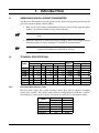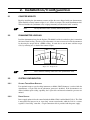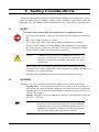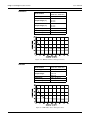
1
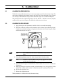
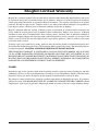
HD-1/HD-2 Series
Dial Weight
Dynamometers
User’s Manual
Purchase Record
Please record all model numbers and serial numbers of your
Magtrol equipment, along with the general purchase information.
The model number and serial number can be found on either
a silver identification plate or white label affixed to each unit.
Refer to these numbers whenever you communicate with a
Magtrol representative about this equipment.
Model Number:
_____________________________
Serial Number:
_____________________________
Purchase Date:
_____________________________
Purchased From:
_____________________________
While every precaution has been exercised in the compilation of this document to
ensure the accuracy of its contents, Magtrol, Inc. assumes no responsibility for errors or
omissions. Additionally, no liability is assumed for any damages that may result from the
use of the information contained within this publication.
Copyright
Copyright ©1999-2006 Magtrol, Inc. All rights reserved.
Copying or reproduction of all or any part of the contents of this manual without the
express permission of Magtrol is strictly prohibited.
1st Edition, rev. A – August 2006
Revisions To This Manual
The contents of this manual are subject to change without prior notice. Should revisions be necessary, updates to all
Magtrol User’s Manuals can be found at Magtrol’s web site at www.magtrol.com/support/manuals.htm.
Please compare the date of this manual with the revision date on the web site, then refer to the manual’s Table of
Revisions for any changes/updates that have been made since this edition.
Revision Date
1st Edition, Revision A – August 2006
Table of Revisions
Date
08/01/06
12/1999
Edition
1st Edition, Rev. A
1st Edition
Change
Redesigned manual to be consistent with Magtrol format.
First PDF version.
Section(s)
all
---
Table of Contents
Revisions To This Manual.................................................................................................................i
Revision Date...................................................................................................................................................................i
Table of Revisions........................................................................................................................................................i
Table of Contents............................................................................................................................ii
Table of Figures......................................................................................................................................................... iii
1. Introduction..................................................................................................................................1
1.1 Unpacking Your Dial Weight Dynamometer.......................................................................................... 1
1.2 Technical Specifications................................................................................................................................. 1
1.2.1Hysteresis Brake Control Power................................................................................................. 1
2. Installation/Configuration.....................................................................................................2
2.1 Counter Weights.................................................................................................................................................. 2
2.2 Dynamometer Leveling.................................................................................................................................... 2
2.3 System Configuration....................................................................................................................................... 2
2.3.1Optional Torque/Speed Readouts................................................................................................. 2
2.3.2 Power Supplies......................................................................................................................................... 2
2.3.3 Connections............................................................................................................................................. 3
2.4 Initial Checkout................................................................................................................................................... 3
3. Testing Considerations.............................................................................................................4
3.1 Safety......................................................................................................................................................................... 4
3.2 Accuracy.................................................................................................................................................................. 4
3.2.1 Torque Scale Graduations............................................................................................................... 5
3.3 Power Dissipation................................................................................................................................................. 5
3.3.1 Power Absorption Curves................................................................................................................. 5
3.4 Fixtures and Couplings.................................................................................................................................... 9
3.5 Windage................................................................................................................................................................... 10
3.6 Friction.................................................................................................................................................................... 10
3.7 Vibration................................................................................................................................................................. 11
3.8 Cogging.................................................................................................................................................................... 11
3.9 Eddy Currents..................................................................................................................................................... 12
3.10Temperature Rise................................................................................................................................................ 12
4. Operating Principles................................................................................................................13
4.1 Speed.......................................................................................................................................................................... 13
4.2 Torque...................................................................................................................................................................... 13
4.2.1 Torque Stability.................................................................................................................................. 13
5. Calibration...................................................................................................................................14
5.1 Calibration Preparation................................................................................................................................ 14
5.2 Calibration Procedure................................................................................................................................... 14
Magtrol Limited Warranty..........................................................................................................15
Claims.............................................................................................................................................................................. 15
ii
User’s Manual
Magtrol Dial Weight Dynamometers
Service Information.......................................................................................................................16
Returning Magtrol equipment for Repair and/or Calibration...................................................... 16
Returning Equipment to Magtrol, Inc. (United States)................................................................. 16
Returning Equipment to Magtrol SA (Switzerland)...................................................................... 16
Table of Figures
2. Installation/Configuration
Figure 2–1 Torque Scale..............................................................................................................................................2
3. Testing Considerations
Figure 3–1
Figure 3–2
Figure 3–3
Figure 3–4
Figure 3–5
Figure 3–6
Figure 3–7
Figure 3–8
Figure 3–9
Dynamometer Side View............................................................................................................................6
HD-106-1 Power Absorption Curve..........................................................................................................6
HD-400-1/2 Power Absorption Curve.......................................................................................................7
HD-500-1 Power Absorption Curve . .......................................................................................................7
HD-600-1 Power Absorption Curve..........................................................................................................8
HD-700-1 Power Absorption Curve..........................................................................................................8
HD-705-1 Power Absorption Curve..........................................................................................................9
Examples of Possible Shaft Misalignment...............................................................................................10
Hysteresis Brake Cross-Section...............................................................................................................11
4. Operating Principles
Figure 4–1 Optical Encoder Circuit..........................................................................................................................13
5. Calibration
Figure 5–1 Calibration Setup....................................................................................................................................14
iii
1. Introduction
1.1Unpacking Your Dial Weight Dynamometer
Your Hysteresis Dynamometer was packaged in reusable, shock resistant packing material that will
protect the instrument during normal handling.
1. Make sure the carton contains all dynamometer hardware, counter weights, applicable power
supplies, User Manual CD-Rom, and any other small items.
Note:
The counter weights may be wrapped separately or installed on the
brake.
2. Inspect the contents for any evidence of damage in shipping. In the event of shipping damage,
immediately notify the carrier and Magtrol’s Customer Service Department.
1.2
Note:
Technical Specifications
Model
HD-106-1
HD-400-1
HD-400-2
HD-500-1
HD-600-1
HD-700-1
HD-705-1
1.2.1
Save all shipping cartons and packaging material for reuse when
returning the instrument for calibration or servicing.
Power Ratings
Full Scale Torque
Maximum
Speed
Range One
Range Two
Range Three
5 Minutes Continuous
oz·in accuracy oz·in accuracy oz·in accuracy
rpm
W
W
0.5
3.5 %
1
2%
2
1%
30,000
35
7
2
2%
8
2%
16
1%
20,000
200
55
8
2%
16
1%
32
1%
20,000
200
55
25
2%
50
1 % 100
1%
15,000
400
80
50
1 % 100
1 % 200
1%
10,000
600
100
100
1 % 200
1 % 400
1%
10,000
700
150
200
1 % 400
1 % 800
1%
8,000
1400
300
Hysteresis Brake Control Power
Hysteresis brakes require direct current for torque control. They will not respond to alternating
current above a few Hz. The nominal voltage rating for all Magtrol Hysteresis Brakes is 28 VDC.
The following is a listing of the resistance and current for each brake, by dynamometer model.
Resistance
Ω
171
80
120
80
40
Model
HD-106-1
HD-400-1/2
HD-500-1
HD-700-1
HD-705-1
F.S. Current
A
0.164
0.350
0.233
0.350
0.700
2. Installation/Configuration
2.1
Counter Weights
Begin by installing the dynamometer counter weights that were shipped with your dynamometer.
There should be as many counter weights, 2 or 3, as there are torque scales on the dynamometer dial.
This total includes the (minimum scale) weight permanently attached to the brake assembly.
2.2
Note:
The dynamometer brake assembly should swing freely.
Dynamometer Leveling
Level the dynamometer base plate in all planes. The bubble level device on the base plate is convenient
for front-to-back leveling. For side-to-side adjustment, it is more accurate to level the dynamometer
by observing the torque dial for a ZERO reading. It works best to use the most sensitive torque
scale, by removing one, or both of the counter weights.
0
Figure 2–1 Torque Scale
Note:
There should be nothing connected to the dynamometer shaft.
2.3System Configuration
2.3.1
Optional Torque/Speed Readouts
If an optional torque or speed reading instrument, or Model 5400 Tachometer, is ordered with the
dynamometer, a 14-pin cable for the tachometer generator is included, If the dynamometer was
ordered without speed reading capability, the 14-pin cable and internal tachometer generator are
omitted.
2.3.2
Power Supplies
Power supply options for brake control include the Model 5200-2 and the Model 5210-2. The 5200
is unregulated and operates in an “open loop” current control mode; while the 5210 is a currentregulated “closed loop” controller. A 2-pin connection cable is provided with the power supply.
User’s Manual
Magtrol Dial Weight Dynamometers
2.3.3
Connections
Connect all items together. The dynamometer controller and torque/speed readout (if applicable)
interconnections are straight forward using the cord sets.
2.4Initial Checkout
1.Be sure the TORQUE control on the power supply is off (CCW).
2. Turn on the speed readout device (if applicable) and the torque controller.
3. Rotate the dynamometer shaft manually while simultaneously adjusting the TORQUE
CONTROL clockwise very slowly.
4. Stop when you begin to feel resistance occurring on the shaft.
5. If there is a speed reading instrument, note the speed (rpm) reading.
6. Return the TORQUE CONTROL to zero.
Note:
With the TORQUE CONTROL off, you may notice slight torque
pulsations on the shaft. This is normal. For a further description
of “salient poles” please refer to Section 3.8 Cogging.
3. Testing Considerations
A number of factors must be taken into consideration before running a test including safety, accuracy,
power dissipation, fixturing, couplings, windage, friction, vibration, cogging, Eddy currents and
temperature rise. The following sections describe these factors, and their effects, in further detail.
3.1
Safety
For general safety considerations, please follow these few common-sense rules:
•Be sure that your coupling is adequately rated for the speed and torque that you intend to
run.
• Make sure all rotating elements are covered.
• Always wear safety glasses when working around dynamometer test equipment.
• Do not wear loose clothing or ties when working around dynamometer test equipment.
• Never allow anyone to stand close to the side of, or lean over, a rotating shaft coupling.
• Insulate electrical (internal and external) motor connections.
Caution:
A power-line
fault into the dynamometer frame could pass a
transient surge through all interconnected instruments, any
computer in use or operating personnel with dangerous and costly
consequences!
• Always connect the motor frame to a high current capacity (water pipe) earth ground.
•Be sure the motor control circuit breakers cannot be bypassed by accident. Variable autotransformers are especially hazardous!
• When operating dynamometers with blowers, hearing protection must be worn.
3.2
Accuracy
Following, is a list of several factors that affect the apparent accuracy of the torque readout.
• Coupling Losses: If the coupling becomes hot to the touch, or if the dynamometer or
motor vibrate after a period of running, coupling loss error could occur up to several percent
depending on the size of the motor and dynamometer. For more detail, refer to Section 3.4
– Fixtures and Couplings.
• Windage: Negligible at speeds up to 6000 rpm. This effect is described more extensively
in Section 3.5 – Windage.
Note:
Much of the above is dependent upon motor horsepower,
fixturing and other circumstances beyond the control of Magtrol.
If reasonable care is exercised, and calibration and maintenance are
performed on a regular basis, motor test data accuracy better than
1.5% of torque-speed value can generally be expected.
User’s Manual
Magtrol Dial Weight Dynamometers
3.2.1
Torque Scale Graduations
Some torque scale graduations are more difficult to read (rapidly) than others. What usually works
well for most people, is to record torque data points from the easiest reading scale; then correct all
data to correspond to the particular range (counterweight) selected, by multiplying (or dividing) by
2 or 4.
3.3
Power Dissipation
All Magtrol Dynamometers are power absorption instruments. As a dynamometer loads a test
motor, it is absorbs horsepower from the motor into the hysteresis brake. The brake then converts
this mechanical energy into heat.
There are finite limits to the amount of energy and resulting temperature rise that any absorption
brake can withstand. Rapidly rising operating temperatures from excessive power input can cause
severe mechanical distortion of the rotor assembly. This, in turn, may cause the rotating assembly
to contact the stationary members that surround it. Once this happens, metal transfer and ultimately
seizing of the brake assembly may occur.
Excessive power over extended periods of time may result in more obscure damage including
breakdown of bearing lubricants and degradation of magnetic coil insulation.
3.3.1
Power Absorption Curves
The following graphs (Figures 3–1 through 3–6) represent the maximum power (heat) that
the dynamometer can dissipate over time. The specifications shown are conditional upon the
following:
• Maximum brake temperature = 100 °C (212 °F)
• Ambient temperature = 25±5 °C (77±9 °C)
The following torque/speed-to-horsepower conversion formulas are provided for your convenience.
They are sufficiently accurate (within 1%) to establish horsepower (hp) for use in the heat rise
curves.
hp = oz·in × rpm × 1.00 × 10⁻⁶
hp = lb·ft × rpm × 1.90 × 10⁻⁴
hp = oz·ft × rpm × 1.19 × 10⁻⁵
hp = lb·in × rpm × 1.59 × 10⁻⁵
hp = g·cm × rpm × 1.38 × 10⁻⁸
hp = N·m × rpm × 1.40 × 10⁻⁴
Note:
Please take a moment to familiarize yourself with any limitations
that may apply to your specific dynamometer and motor testing
requirements.
User’s Manual
Magtrol Dial Weight Dynamometers
The following sketch shows the identifications for shaft height “H” and diameter “D” used in the
following specifications.
Figure 3–1 Dynamometer Side View
HD-106-1
Shaft Diameter
Shaft Height
Torque Ranges
Input Inertia
Maximum Speed
Maximum Input Power
0.1245 in / 0.1250 in
(3.163 mm / 3.175 mm)
3.50 in (88.9 mm)
0.5 oz·in
1.0 oz·in
2.0 oz·in
7.04 × 10⁻⁷ lb·ft·s²
30,000 rpm
40 W
Figure 3–2 HD-106-1 Power Absorption Curve
User’s Manual
Magtrol Dial Weight Dynamometers
HD-400-1/2
Shaft Diameter
Shaft Height
Torque Ranges (-1)
Torque Ranges (-2)
Input Inertia
Maximum Speed
Maximum Input Power
0.2495 in / 0.2500 in
(6.338 mm / 6.350 mm)
3.50 in (88.9 mm)
2 oz·in
8 oz·in
16 oz·in
8 oz·in
16 oz·in
32 oz·in
1.55 × 10⁻⁵ lb·ft·s²
25,000 rpm
190 W
Figure 3–3 HD-400-1/2 Power Absorption Curve
HD-500-1
Shaft Diameter
Shaft Height
Torque Ranges
Input Inertia
Maximum Speed
Maximum Input Power
0.3745 in / 0.3750 in
(9.512 mm / 9.525 mm)
4.00 in (101.6 mm)
25 oz·in
50 oz·in
100 oz·in
8.05 × 10⁻⁵ lb·ft·s²
20,000 rpm
375 W
Figure 3–4 HD-500-1 Power Absorption Curve
User’s Manual
Magtrol Dial Weight Dynamometers
HD-600-1
Shaft Diameter
Shaft Height
Torque Ranges
Input Inertia
Maximum Speed
Maximum Input Power
0.4995 in / 0.5000 in
(12.687 mm / 12.700 mm)
4.812 in (122.22 mm)
50 oz·in
100 oz·in
200 oz·in
2.34 × 10⁻⁵ lb·ft·s²
20,000 rpm
550 W
Figure 3–5 HD-600-1 Power Absorption Curve
HD-700-1
Shaft Diameter
Shaft Height
Torque Ranges
Input Inertia
Maximum Speed
Maximum Input Power
0.4995 in / 0.5000 in
(12.687 mm / 12.700 mm)
5.875 in (149.2 mm)
100 oz·in
200 oz·in
400 oz·in
5.51 × 10⁻⁴ lb·ft·s²
15,000 rpm
650 W
Figure 3–6 HD-700-1 Power Absorption Curve
User’s Manual
Magtrol Dial Weight Dynamometers
HD-705-1
Shaft Diameter
Shaft Height
Torque Ranges
Input Inertia
Maximum Speed
Maximum Input Power
0.4995 in / 0.5000 in
(12.687 mm / 12.700 mm)
5.875 in (149.2 mm)
200 oz·in
400 oz·in
800 oz·in
1.101 × 10⁻³ lb·ft·s²
10,000 rpm
1400 W
Figure 3–7 HD-705-1 Power Absorption Curve
3.4
Fixtures and Couplings
When mounting the test motor, please consider the following:
• Construct precise fixtures that provide proper shaft alignment.
• Secure the test motor in the fixture to prevent torsional movement and bolt the fixture to the
dynamometer base plate.
•Give consideration to the interaction of materials between the motor and test fixture. For
example, a (magnetic) steel plate placed against the exposed lamination of an open frame
motor can significantly influence performance. Some thin shell PM (permanent magnet)
motors may be similarly affected.
• The dynamometer base plate material is an aluminum tool plate that is easily drilled and
tapped. The use of helix thread inserts is a good idea if you are going to interchange fixtures
often.
Note:
For an additional charge, Magtrol can perform base plate
modifications.
User’s Manual
Magtrol Dial Weight Dynamometers
The following diagram illustrates examples of possible shaft misalignment.
ANGULAR
PARALLEL OFFSET
Figure 3–8 Examples of Possible Shaft Misalignment
The use of high quality double flexure couplings is recommended to help correct any misalignment
problems. This type of coupling—two flexing elements separated by a solid link—inherently tolerates
greater parallel offset. If you would like more specific coupling recommendations, contact Magtrol
Technical Assistance. For precise misalignment tolerances, consult your coupling manufacturer.
3.5
Windage
Although a smooth surface, the dynamometer rotor will drag air around with it. This air friction
is tangential to the surface and impinges upon the stationary field assembly. The viscous drag that
results then becomes part of the motor load and torque reading. However, there is a small amount
of air dissipated as pumping loss. Since this appears as a load on the motor, not measured by the
dynamometer, it becomes a source of error.
Windage effects on accuracy tests have been conducted on all Magtrol dynamometers. The percentage
of torque loss due to windage ranges between 0.025% and 0.20% of full scale at maximum rated
rpm. The larger percentage applies toward the smallest capacity dynamometer (HD-106). Because
windage is proportional to the square of speed, it magnifies rapidly above rated speed. Conversely,
at one half of the rated speed, the effect becomes immeasurably small.
3.6
Friction
Friction of the shaft bearings is a measurable load, but some friction can exist in the carrier bearing.
When correctly loaded and lubricated, the friction is insignificant. The value may be quantitatively
established by the following procedure.
1. Remove all attachments to the dynamometer shaft.
2. Swing the brake assembly up to full scale - by hand.
3. Carefully allow the assembly to return to zero without swinging back and forth.
4. Repeat steps 2 and 3—this time in the opposite direction—and note the reading.
The difference between zero and the second reading should be within the accuracy specifications
listed in Section 1.2 – Technical Specifications. During actual motor testing there is usually enough
system vibration to “settle” negating frictional effects. If excessive drag is present, mechanical
realignment may be required, dependent upon dynamometer size. Certain mechanical factors need
to be determined before corrective action proceeds. Please contact Magtrol Technical Assistance.
10
User’s Manual
Magtrol Dial Weight Dynamometers
3.7
Vibration
All rotating dynamometer assemblies are precision balanced, however, the dynamometer shaft is
cantilevered. This may cause vulnerability to radial forces.
At high speeds, some vibration and noise are inevitable but not necessarily harmful. However,
excessive resonant vibrations, caused by bent shafts, poor alignment and out of balance couplings
will produce excessive data errors and are a safety hazard.
3.8
Warning!
S h a f t c o u p l i n g s o p e r at i n g at s p e e ds
above their design limits are extremely
hazardous. Many couplings contain somewhat
loosely supported flexure elements. When
overdriven, excessive centrifugal force
may displace them out of axial alignment.
As this happens, they immediately begin to
absorb energy resulting in severe vibration
and destruction of the coupling.
Cogging
ROTOR POLES
CASE
POLE
ROTOR
ASSEMBLY
N
N
N
S
S
S
Figure 3–9 Hysteresis Brake Cross-Section
This cross-section shows (by one tooth) the magnetic relationship of the hysteresis brake elements.
If the dynamometer shaft is at rest with torque applied, and if the torque control is then reduced to
zero, a magnetic salient pole will be temporarily imposed on the rotor of the brake.
If the shaft is then rotated slowly, the magnetic poles on the rotor will attempt to align with the adjacent
case-pole tooth form. This is often referred to as “cogging”. The action is sinusoidal—first it tries to
resist rotation and then, as the rotor passes through the tooth form, it subsequently supports rotation.
At a few hundred rpm, these forces integrate resulting in an effective torque of nearly zero.
To avoid magnetic cogging, before the shaft comes to rest, reduce the torque control to zero.
To remove cogging, once established, reapply current on the dynamometer. Then, decrease the
current to zero while simultaneously rotating the dynamometer shaft.
11
User’s Manual
3.9
Magtrol Dial Weight Dynamometers
Eddy Currents
There is some Eddy current generation within the brake rotor. These magnetically induced currents
cause an increase in brake torque proportional to speed.
The larger the hysteresis brake, the higher the rotor surface velocity. Additionally, as brakes become
larger the rotor cross-sectional area increases. Each of these factors increase Eddy current generation.
The combination results in speed-related torque increase, exhibiting a more pronounced effect on
larger dynamometers.
On the smaller dynamometer sizes, 2% to 4%/1000 rpm is typical.
3.10
Temperature Rise
Temperature rise has a more complex effect on hysteresis brake load torque and is difficult to quantify.
As the temperature of the brake increases, differential expansions cause dimensional changes that
tend to increase torque. Conversely, electrical resistance in the rotor increases with temperature,
resulting in decreased Eddy current generation and torque, all in a variable frame.
Where current and speed remain fixed, there may be a gradual torque increase over a period of a
few moments. This will generally stabilize at 0.5% (for small dynamometers, up to HD-500-1) to
1.5% of the starting torque value, per 1000 rpm of applied speed.
12
4. Operating Principles
4.1Speed
If your dynamometer contains a speed pickup, there will be two cords: one terminating with a 2-pin
plug for the brake power, the other is a 14-pin plug servicing an optical encoder.
This encoder consists of an infrared transmitter/receiver pair. On the end of the dynamometer shaft,
positioned between the LED and detector, is an optical disc with opaque and clear segments. Rotation
of the disc results in the detector generating a frequency of 60 pulses per shaft revolution.
5V (Pin 7)
R2
200
R1
470
5
2
OPB963
4
1
3
U1
Fo (Pin 10)
(Pin 8)
Figure 4–1 Optical Encoder Circuit
4.2Torque
Torsional force, acting upon the hysteresis brake, is produced by the test motor, and applied to the
brake’s rotor-shaft assembly. Whatever torque exists on the rotor-shaft, must be reacted upon equally
by the suspended brake-dial-weight assembly.
Since the brake assembly is imbalanced by the suspended weight attached to it, torsional force will
lift the weight. The graduated dial provides a readout value equal to this torque. Once the weights
are calibrated to match the dial graduations, the system accuracy becomes permanently fixed.
When torque is defined by a point on the radius of a weight, lifted in a circular motion, the scale
derivation is inherently a cosine function - thus, the nonlinear scale graduations.
4.2.1
Torque Stability
A major advantage in using a hysteresis brake as a loading means, is the ability to produce torque
essentially independent of speed. This permits very low speed and locked rotor torque testing.
Three factors have a minor secondary influence on hysteresis brake torque. They are:
•Hysteresis brake control current (see Section 1.2.1)
• Eddy current (see Section 3.9)
• Temperature rise (see Section 3.10)
Please note that the torque changes as a result of these influences are always part of the actual torque
measured—as applied to a test motor—and not errors.
13
5. Calibration
5.1
Calibration Preparation
To check the torque calibration accuracy, it is necessary to apply a precisely known torque value. The
most accurate method to apply a known torque is with the use of a beam and weight system. Various
sizes of torque calibration beams and precision calibration weights are available from Magtrol.
The pin location on the torque beam precisely fixes the distance. Therefore, the force (weight)
required will be equal to the torque value divided by the distance on the beam.
Calibration Procedure
1. Apply full torque to the dynamometer, until the shaft is restrained from rotating.
2. Install the calibration beam on the dynamometer shaft as shown in the following diagram.
Lock the beam with the locking screw against the flat on the shaft. Do not hang the weight
until instructed to do so in step 4.
RQ
UE
With the Base Plate
and the Beam level Dial Reading - D x W
TO
5.2
level
D
W
level
Figure 5–1 Calibration Setup
Note:
The calibration beam must be maintained exactly level at all
times.
3. Using lightweight (but strong) line, form a loop and attach it to the weight.
Note:
Do not use a wire hook. Hooks will generally apply the force slightly
off the center line of the pin.
4. Suspend a known weight, at a known distance, from the beam. See Section 5.1 – Calibration
Preparation.
5. While preventing the beam from rotating, and maintaining it in a level position, lift the
weight-dial assembly until a balance is attained between the assembly and the beam.
6.Observe the deviation, if any.
7. Remove the calibration beam.
The dynamometer is calibrated and ready for motor testing.
14
Magtrol Limited Warranty
Magtrol, Inc. warrants its products to be free from defects in material and workmanship under normal use and service
for a period of twenty-four (24) months from the date of shipment. Software is warranted to operate in accordance
with its programmed instructions on appropriate Magtrol instruments. This warranty extends only to the original
purchaser and shall not apply to fuses, computer media, or any other product which, in Magtrol’s sole opinion, has
been subject to misuse, alteration, abuse or abnormal conditions of operation or shipping.
Magtrol’s obligation under this warranty is limited to repair or replacement of a product which is returned to the
factory within the warranty period and is determined, upon examination by Magtrol, to be defective. If Magtrol
determines that the defect or malfunction has been caused by misuse, alteration, abuse or abnormal conditions of
operation or shipping, Magtrol will repair the product and bill the purchaser for the reasonable cost of repair. If the
product is not covered by this warranty, Magtrol will, if requested by purchaser, submit an estimate of the repair
costs before work is started.
To obtain repair service under this warranty, purchaser must forward the product (transportation prepaid) and a
description of the malfunction to the factory. The instrument shall be repaired at the factory and returned to purchaser,
transportation prepaid. MAGTROL ASSUMES NO RISK FOR IN-TRANSIT DAMAGE.
THE FOREGOING WARRANTY IS PURCHASER’S SOLE AND EXCLUSIVE REMEDY AND IS IN LIEU
OF ALL OTHER WARRANTIES, EXPRESSED OR IMPLIED, INCLUDING BUT NOT LIMITED TO ANY
IMPLIED WARRANTY OF MERCHANTABILITY, OR FITNESS FOR ANY PARTICULAR PURPOSE OR USE.
MAGTROL SHALL NOT BE LIABLE FOR ANY SPECIAL, INDIRECT, INCIDENTAL, OR CONSEQUENTIAL
DAMAGES OR LOSS WHETHER IN CONTRACT, TORT, OR OTHERWISE.
Claims
Immediately upon arrival, purchaser shall check the packing container against the enclosed packing list and shall,
within thirty (30) days of arrival, give Magtrol notice of shortages or any nonconformity with the terms of the order.
If purchaser fails to give notice, the delivery shall be deemed to conform with the terms of the order.
The purchaser assumes all risk of loss or damage to products upon delivery by Magtrol to the carrier. If a product is
damaged in transit, PURCHASER MUST FILE ALL CLAIMS FOR DAMAGE WITH THE CARRIER to obtain
compensation. Upon request by purchaser, Magtrol will submit an estimate of the cost to repair shipment damage.
15
Service Information
Returning Magtrol equipment for Repair and/or Calibration
Before returning equipment to Magtrol for repair and/or calibration, please visit Magtrol’s Web site at
http://www.magtrol.com/support/rma.htm to begin the Return Material Authorization (RMA) process. Depending on
where the equipment is located and which unit(s) will be returned, you will be directed to either ship your equipment
back to Magtrol, Inc. in the United States or Magtrol SA in Switzerland.
Returning Equipment to Magtrol, Inc. (United States)
When returning equipment to Magtrol, Inc.’s factory in the United States for repair and/or calibration, a completed
Return Material Authorization (RMA) form is required.
1.Visit Magtrol’s Web site at http://www.magtrol.com/support/rma.htm to begin the RMA process.
2.
Complete the RMA form online and submit.
3.
An RMA number will be issued to you via e-mail. Include this number on all return documentation.
4.
Ship your equipment to:
Magtrol, Inc.
70 Gardenville Parkway
Buffalo, NY 14224
Attn: Repair Department
5.
After Magtrol’s Repair Department receives and analyzes your equipment, a quotation listing all the necessary
parts and labor costs, if any, will be faxed or e-mailed to you.
6.
After receiving your repair estimate, provide Magtrol with a P.O. number as soon as possible. A purchase
order confirming the cost quoted is required before your equipment can be returned.
Returning Equipment to Magtrol SA (Switzerland)
If you are directed to ship your equipment to Switzerland, no RMA form/number is required. Just send your equipment
directly to Magtrol SA in Switzerland and follow these shipment instructions:
1.
Ship your equipment to:
Magtrol SA
After Sales Service
Centre technologique Montena
1728 Rossens / Fribourg
Switzerland
VAT No: 485 572
2.
Please use our forwarder : TNT • 1-800-558-5555 • Account No 154033
Only ship ECONOMIC way (3 days max. within Europe)
3.
Include the following documents with your equipment:
• Delivery note with Magtrol SA’s address (as listed above)
• Three pro forma invoices with:
• Your VAT number
•Value - for customs purposes only
• Description of returned goods •Origin of the goods (in general, Switzerland)
• Noticed failures
4.
A cost estimate for repair will be sent to you as soon as the goods have been analyzed. If the repair charges
do not exceed 25% the price of a new unit, the repair or calibration will be completed without requiring prior
customer authorization.
16
Testing, Measurement and Control of Torque-Speed-Power • Load-Force-Weight • Tension • Displacement
Magtrol Inc
70 Gardenville Parkway
Buffalo, New York 14224 USA
Phone: +1 716 668 5555
Fax: +1 716 668 8705
E-mail: [email protected]
Magtrol SA
Centre technologique Montena
1728 Rossens / Fribourg, Switzerland
Phone: +41 (0)26 407 3000
Fax: +41 (0)26 407 3001
E-mail: [email protected]
www.magtrol.com
Subsidiaries in:
• Germany
• France
• Great Britain
• China
Worldwide Network
of Sales Agents