1
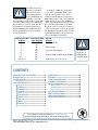
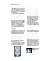
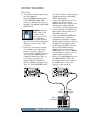
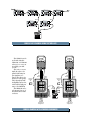
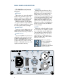
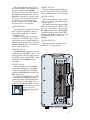
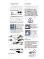
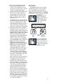
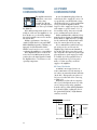
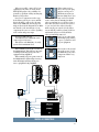
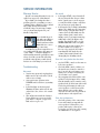
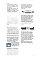
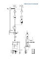
SRM350 2-WAY
ACTIVE LOUDSPEAKER
USER’S MANUAL
IMPORTANT SAFETY INSTRUCTIONS
1. Read these instructions.
13. Unplug this apparatus during lightning storms or when unused for
long periods of time.
14. Refer all servicing to qualified service personnel. Servicing is
required when the apparatus has been damaged in any way, such as
power-supply cord or plug is damaged, liquid has been spilled or objects
have fallen into the apparatus, the apparatus has been exposed to rain
or moisture, does not operate normally, or has been dropped.
2. Keep these instructions.
3. Heed all warnings.
4. Follow all instructions.
5. Do not use this apparatus near water.
15. This apparatus shall not be exposed to dripping or splashing, and no
object filled with liquids, such as vases, shall be placed on the apparatus.
6. Clean only with dry cloth.
7. Do not block any ventilation openings. Install in accordance with the
manufacturer’s instructions.
8. Do not install near any heat sources such as radiators, heat registers,
stoves, or other apparatus (including amplifiers) that produce heat.
9. Do not defeat the safety purpose of the polarized or grounding-type
plug. A polarized plug has two blades with one wider than the other. A
grounding-type plug has two blades and a third grounding prong. The
wide blade or the third prong are provided for your safety. If the
provided plug does not fit into your outlet, consult an electrician for
replacement of the obsolete outlet.
10. Protect the power cord from being walked on or pinched
particularly at plugs, convenience receptacles, and the point where they
exit from the apparatus.
11. Only use attachments/accessories specified by the manufacturer.
12. Use only with a cart, stand, tripod, bracket, or table specified by
the manufacturer, or sold with the apparatus. When a cart is used, use
caution when moving the cart/apparatus combination to avoid injury
from tip-over.
PORTABLE CART WARNING
Carts and stands - The
Component should be used
only with a cart or stand
that is recommended by
the manufacturer.
A Component and cart
combination should be
moved with care. Quick
stops, excessive force, and
uneven surfaces may cause
the Component and cart
combination to overturn.
16. This apparatus has been designed with Class-I construction and
must be connected to a mains socket outlet with a protective earthing
connection (the third grounding prong).
17. This apparatus has been equipped with an all-pole, rocker-style AC
mains power switch. This switch is located on the rear panel and should
remain readily accessible to the user.
18. This apparatus does not exceed the Class A/Class B (whichever is
applicable) limits for radio noise emissions from digital apparatus as set
out in the radio interference regulations of the Canadian Department of
Communications.
ATTENTION — Le présent appareil numérique n’émet pas de bruits
radioélectriques dépassant las limites applicables aux appareils
numériques de class A/de class B (selon le cas) prescrites dans le
réglement sur le brouillage radioélectrique édicté par les ministere des
communications du Canada.
19. Exposure to extremely high noise levels may cause permanent
hearing loss. Individuals vary considerably in susceptibility to noise-induced
hearing loss, but nearly everyone will lose some hearing if exposed to
sufficiently intense noise for a period of time. The U.S. Government’s
Occupational Safety and Health Administration (OSHA) has specified the
permissible noise level exposures shown in the following chart.
CAUTION
AVIS
RISK OF ELECTRIC SHOCK
DO NOT OPEN
RISQUE DE CHOC ELECTRIQUE
NE PAS OUVRIR
CAUTION: TO REDUCE THE RISK OF ELECTRIC SHOCK
DO NOT REMOVE COVER (OR BACK)
NO USER-SERVICEABLE PARTS INSIDE
REFER SERVICING TO QUALIFIED PERSONNEL
ATTENTION: POUR EVITER LES RISQUES DE CHOC
ELECTRIQUE, NE PAS ENLEVER LE COUVERCLE. AUCUN
ENTRETIEN DE PIECES INTERIEURES PAR L'USAGER. CONFIER
L'ENTRETIEN AU PERSONNEL QUALIFIE.
AVIS: POUR EVITER LES RISQUES D'INCENDIE OU
D'ELECTROCUTION, N'EXPOSEZ PAS CET ARTICLE
A LA PLUIE OU A L'HUMIDITE
The lightning flash with arrowhead symbol within an equilateral
triangle is intended to alert the user to the presence of uninsulated
"dangerous voltage" within the product's enclosure that may be
of sufficient magnitude to constitute a risk of electric shock to persons.
Le symbole éclair avec point de flèche à l'intérieur d'un triangle
équilatéral est utilisé pour alerter l'utilisateur de la présence à
l'intérieur du coffret de "voltage dangereux" non isolé d'ampleur
suffisante pour constituer un risque d'éléctrocution.
The exclamation point within an equilateral triangle is intended to
alert the user of the presence of important operating and maintenance
(servicing) instructions in the literature accompanying the appliance.
Le point d'exclamation à l'intérieur d'un triangle équilatéral est
employé pour alerter les utilisateurs de la présence d'instructions
importantes pour le fonctionnement et l'entretien (service) dans le
livret d'instruction accompagnant l'appareil.
WARNING — To reduce the risk of fire or electric
shock, do not expose this appliance to rain or moisture.
2
Lend Me Your Ears
Exposure to extremely
high noise levels may
cause permanent hearing loss. Individuals vary
considerably in susceptibility to noise-induced hearing loss, but nearly everyone will
lose some hearing if exposed to sufficiently
intense noise for a period of time. The U.S.
Government’s Occupational Safety and
Health Administration (OSHA) has specified the permissible noise level exposures
shown in this chart.
Duration Per Day Sound Level dBA,
In Hours
Slow Response
8
90
6
92
4
95
3
97
2
100
1.5
102
1
105
0.5
110
0.25 or less
115
According to OSHA, any exposure in
excess of these permissible limits could
result in some hearing loss. To ensure
against potentially dangerous exposure to
high sound-pressure levels, it is recommended that all persons exposed to equipment
capable of producing these levels use hearing
protectors while this unit is in operation.
Ear plugs or protectors in the ear canals or
over the ears must be worn when operating
this amplification system in order to prevent
a permanent hearing loss if exposure is in
excess of the limits set forth here.
Typical
Example
Duo in small club
Subway Train
Very loud classical music
The SRM350
can produce a
maximum SPL
of 121 dB @ 1m.
Tami screaming at Adrian about deadlines
Loudest parts at a rock concert
CONTENTS
IMPORTANT SAFETY INSTRUCTIONS ..................... 2
INTRODUCTION ....................................................... 4
HOOKUP DIAGRAMS ............................................... 6
Quick Start ........................................................ 6
REAR PANEL DESCRIPTION .................................... 8
IEC Socket .................................................. 8
POWER Switch ............................................ 8
POWER Indicator ......................................... 8
CONTOUR .................................................. 8
LEVEL ......................................................... 8
MIC/LINE Switch ......................................... 9
SIGNAL Indicator ........................................ 9
LIMIT Indicator ............................................ 9
INPUT Connector ........................................ 9
THRU Connector ......................................... 9
Accessory Plate .......................................... 9
CONNECTIONS ......................................................
PLACEMENT ..........................................................
THERMAL CONSIDERATIONS ................................
AC POWER CONSIDERATIONS ..............................
SERVICE INFORMATION ........................................
Warranty Service .............................................
Troubleshooting ...............................................
Repair .............................................................
CARE AND MAINTENANCE ....................................
SRM350 SPECIFICATIONS .....................................
SRM350 BLOCK DIAGRAM ....................................
SRM350 LIMITED WARRANTY ...............................
Don’t forget to visit our website at www.mackie.com
for more information about these and other Mackie products.
Part No. 0008034-90 Rev. C 09/05
©2003-2005 LOUD Technologies Inc. All Rights Reserved.
10
10
12
12
14
14
14
16
16
17
18
19
R
3
INTRODUCTION
Thank you for choosing LOUD Technologies’
Mackie active sound reinforcement speakers.
The SRM350 is an active two-way loudspeaker capable of extremely high sound
pressure levels, and designed to give you the
best performance of any loudspeaker in its
class and price range.
When we designed the SRM350s older
sibling, the SRM450, our goal was to build
a sound reinforcement speaker with the
same fidelity and precision found in our reknowned HR824 studio monitors.
Apparently, people liked what they heard.
Now, our goal for the SRM350 is to make
the sound even better with improved active
electronics, but delivered in a more compact
size. We think you’ll agree that the SRM350
sound quality and accuracy reaches this
goal and more. The result is a compact
sound reinforcement system equally at
home in a concert setting, in the studio, impromptu concerts on the studio roof, in the
cinema, or in a home theater.
The Transducers
The SRM350 active speakers feature a 10˝
high-power low-frequency woofer and a 1.4˝
titanium diaphragm high-output precision
compression driver. This high- frequency
driver is mounted on an acoustically nonresonant exponential waveguide, providing
a wide, controlled dispersion and precise reproduction of the critical upper mid-range
and high frequencies. The result is an unbelievably smooth off-axis response that
allows everyone in the audience to experience the same high-resolution audio no
matter where they are seated.
Each driver has been specifically designed
by our engineers for optimum performance
in the lightweight high-strength cabinet.
Power Amplifiers
To power these beautiful things, each
SRM350 includes two power amplifiers.
They include the following features:
• The low-frequency amplifier produces
165 continuous watts before clipping.
• The high-frequency amplifier produces
30 continuous watts before clipping.
• Both amplifiers are a Class H design,
which uses a dual power supply for
improved power and thermal efficiency.
The amplifiers operate on the lower
voltage rails until the signal requires
more power, at which point the high
voltage rails seamlessly kick in to
provide additional power.
• An Active Protection Management
System monitors the output levels from
both amplifiers as well as the operating
temperature of the amplifiers. When the
output from either amplifier begins to
clip, a limiter gently reduces the input
signal level until the output is no longer
clipping. Likewise, if the temperature of
either of the amplifers begins to exceed
a safe operating level, the input signal is
elegantly adjusted to keep the temperature at a desired operating level.
• The low-frequency amplifier also has a
Dynamic Bass Boost circuit. Our ears
are more sensitive to bass frequencies at
high volume levels than at softer volumes. This unique circuit automatically
reduces the low frequencies below 70
Hz as the volume of the speakers goes
up. This results in improved efficiency
for the low-frequency amplifier because
it is not wasting power trying to reproduce frequencies we hear better at loud
volumes. Instead, the power is used for
the frequencies where it is needed,
resulting in a louder sound.
Warning: Although the
amplifiers have these
protection circuits, you
must still make sure the
LIMIT light is not blinking continuously. If it is, turn down your
mixer faders, or preamplifier gain, or turn
down the SRM350 LEVEL control.
4
The Crossover
The Active Advantage
The built-in electronic crossover is a
24 dB/octave Linkwitz-Riley design. Although
more expensive than other crossover designs,
the benefits provided by the Linkwitz-Riley
design have been well documented. These
benefits include:
• Absolutely flat frequency response
throughout the bandpass, without the
characteristic ripple near the crossover
point exhibited by other designs.
• The sharp 24 dB per octave roll-off of
the filters ensures that the transducers
aren’t reproducing frequencies outside
of their capabilities.
• The acoustic sum of the two driver
responses is unity at the crossover
frequency, resulting in perfect power
response.
• Our heroic engineers have worked
carefully to ensure that the SRM350
also provides perfect phase response.
This diligence has yielded phenomenal
accuracy, even if you are standing 20
feet away.
There are a number of advantages to using an active speaker system over a passive
loudspeaker:
• The internal crossover is active, and its
low power circuitry operates on linelevel signals. It does not waste
speaker-level power like a passive
crossover with large coils, caps, and
resistors.
• The input signals are crossed over
before they reach the amplifiers, so each
amplifier only receives the correct
frequency range for its driver.
• The amplifiers are designed specifically
for these speaker load impedances.
There is no guesswork as to what load
each amplifier has to drive, so they can
provide maximum acoustic output from
the speakers, yet minimize the danger of
speaker damage due to overdriving a
lesser amplifier.
• The connecting wires between the
amplifier outputs and the drivers are
kept to a minimum, so the damping
factor of the amplifier isn’t compromised by the resistance of long speaker
cables. In addition, all the power from
the amplifier is transferred directly to
the drivers with no speaker cable losses.
• The acoustic sum of the outputs from
the two drivers is optimized electronically, as well as physically, so the
amplitude response is flat and there is
no lobing error.
• The presence of active circuits within
the speaker cabinet allow the designer
to add on extra details, such as a high
quality mic/line input section and
optional accessory modules.
In short, all the complex interconnected
components in the system are designed to
work in harmony with each other to produce the best possible sound.
The Cabinet
The SRM350 cabinet was designed to be
the strongest molded composite cabinet on
the planet. This material is as strong as concrete, and rigid enough to prevent unwanted
vibrations in the cabinet. An optional
bracket kit is available for the top and bottom of the cabinet to be used for flying, and
a socket is provided in the bottom of the
cabinet for mounting on a tripod stand.
Although it is an exceptional choice for installed sound situations, its light weight and
durable finish also make it ideal for portable
sound system use. The asymmetrical trapezoidal design of the cabinet makes it easy
to use as a floor wedge for stage monitor
applications.
5
HOOKUP DIAGRAMS
Quick Start
1. Start with the following settings on the
back of the SRM350:
Turn the POWER switch off (down).
Set the CONTOUR and MIC/LINE
switches out. If using a microphone as
the input to the SRM350, push the MIC/
LINE switch in.
WARNING: Turn the
LEVEL control down
(counterclockwise)
before every use. If not,
you could be in for a
startling surprise, especially if the last
time you used it was with a microphone
and now you want to connect a linelevel source.
2. Connect the output from your signal
source (mixing console, microphone,
preamp, or other mic- or line-level
source) directly to the INPUT connector
on the back of the SRM350. This is a
combination XLR and 1/4˝ TRS connector, and accepts balanced or
unbalanced line-level signals from
mixers, preamplifiers, CD players, tape
decks, etc., with the MIC/LINE switch
SRM350
3.
4.
5.
6.
7.
8.
out, and accepts direct connections from
dynamic microphones with the MIC/
LINE switch pushed in.
Connect the supplied AC power cord to
the IEC socket on the back of the
SRM350. Plug the other end into an AC
outlet properly configured with the
correct voltage for your particular model.
Turn on your signal source. Make sure its
Master Volume control (if it has one) is
turned all the way down.
Turn on the SRM350 POWER switch.
Start the signal source, whether it be
speaking into a microphone or starting a
CD player. Adjust any volume controls on
the signal source for normal operation.
Slowly turn up the LEVEL control on
the back of the SRM350 until the
desired volume is reached (and the
LIMIT light does not come on). Always
wear hearing protectors if you are close
when it is playing at high levels.
If there is no sound, always turn down
the SRM350 LEVEL control before
investigating. There may be a mixer or
preamplifier mute or tape switch
engaged, or a mic switch off.
SRM350
ACTIVE SOUND REINFORCEMENT SYSTEM
POWER
LIMIT
SIGNAL
ACTIVE SOUND REINFORCEMENT SYSTEM
POWER
LIMIT
SIGNAL
THRU
THRU
NORMAL
NORMAL
GA
MIC IN
OO
+45
+5dB
12k/AIR
~120 VAC 60Hz
CONTOUR
2.50A 230VA
(+3dB)
GA
MIC IN
OO
LEVEL
100Hz
ON
LINE
MIC
100Hz
DESIGNED BY MACKOIDS IN WOODINVILLE, WA, USA
AND REGGIO EMILIA, ITALY.
+45
+5dB
LEVEL
INPUT
12k/AIR
~120 VAC 60Hz
CONTOUR
2.50A 230VA
(+3dB)
PARALLEL
PARALLEL
ON
INPUT
LINE
MIC
DESIGNED BY MACKOIDS IN WOODINVILLE, WA, USA
AND REGGIO EMILIA, ITALY.
Left
Line level
Output
Right
Line level
Output
1202-VLZ PRO
Mixer or
Preamplifier
SRM350: STEREO OPERATION WITH A MIXER
6
Next
SRM350
SRM350
ACTIVE SOUND REINFORCEMENT SYSTEM
SRM350
ACTIVE SOUND REINFORCEMENT SYSTEM
LIMIT
SIGNAL
POWER
LIMIT
SIGNAL
POWER
100Hz
12k/AIR
~120 VAC 60Hz
CONTOUR
2.50A 230VA
(+3dB)
+45
+5dB
OO
INPUT
LINE
MIC
100Hz
DESIGNED BY MACKOIDS IN WOODINVILLE, WA, USA
AND REGGIO EMILIA, ITALY.
CONTOUR
2.50A 230VA
(+3dB)
INPUT
100Hz
DESIGNED BY MACKOIDS IN WOODINVILLE, WA, USA
AND REGGIO EMILIA, ITALY.
CONTOUR
2.50A 230VA
(+3dB)
INPUT
100Hz
DESIGNED BY MACKOIDS IN WOODINVILLE, WA, USA
AND REGGIO EMILIA, ITALY.
Thru
SRM350
LIMIT
SIGNAL
THRU
12k/AIR
CONTOUR
2.50A 230VA
(+3dB)
PARALLEL
100Hz
~120 VAC 60Hz
NORMAL
ON
PARALLEL
GA
MIC IN
GA
MIC IN
+45
+5dB
LEVEL
LINE
MIC
DESIGNED BY MACKOIDS IN WOODINVILLE, WA, USA
AND REGGIO EMILIA, ITALY.
LIMIT
SIGNAL
NORMAL
OO
(+3dB)
ACTIVE SOUND REINFORCEMENT SYSTEM
POWER
THRU
ON
CONTOUR
2.50A 230VA
INPUT
Thru
SRM350
ACTIVE SOUND REINFORCEMENT SYSTEM
POWER
12k/AIR
~120 VAC 60Hz
Next
+45
+5dB
LEVEL
LINE
MIC
12k/AIR
~120 VAC 60Hz
GA
MIC IN
OO
LEVEL
LINE
MIC
12k/AIR
~120 VAC 60Hz
THRU
ON
+45
+5dB
OO
LEVEL
LIMIT
SIGNAL
NORMAL
GA
MIC IN
PARALLEL
LEVEL
GA
MIC IN
PARALLEL
+45
+5dB
ACTIVE SOUND REINFORCEMENT SYSTEM
POWER
THRU
NORMAL
ON
PARALLEL
OO
SRM350
LIMIT
SIGNAL
NORMAL
ON
PARALLEL
GA
MIC IN
ACTIVE SOUND REINFORCEMENT SYSTEM
POWER
THRU
THRU
NORMAL
ON
OO
+45
+5dB
LEVEL
INPUT
LINE
MIC
100Hz
DESIGNED BY MACKOIDS IN WOODINVILLE, WA, USA
AND REGGIO EMILIA, ITALY.
12k/AIR
~120 VAC 60Hz
CONTOUR
2.50A 230VA
(+3dB)
INPUT
LINE
MIC
DESIGNED BY MACKOIDS IN WOODINVILLE, WA, USA
AND REGGIO EMILIA, ITALY.
1202-VLZPRO
SRM350: DAISY-CHAINING USING THE THRU JACK
The SRM350 can be
used with a Mackie
SWA1501 or SWA1801
subwoofer to create an
incredibly powerful
system.
The active crossover
inside the subwoofer
splits the full range input signal into two
ranges. The subwoofer
plays the low frequency
range through its builtin amplifier and woofer,
and sends the high-pass
range to the SRM350.
The SRM350 can be
pole mounted on top of
the SWA1501 or 1801
as shown.
Pole
Mount
Line-level
Hi-pass
out
Pole
Mount
Power
Cord
Line-level
Hi-pass
out
ACTIVE
Power
Cord
ACTIVE
Full
Range
Full
Range
1202-VLZ PRO
Power
Cords
SWA1501
plays the low
frequencies
Power
Cords
SWA1501
plays the low
frequencies
SRM350: BIAMPING WITH A POWERED SUBWOOFER
7
REAR PANEL DESCRIPTION
The SRM350 has several connectors,
controls, and indicators that you should
understand.
CONTOUR
Pushing in this switch engages a filter
that provides 3 dB of boost to the low and
high frequencies (below 100 Hz and above
12 kHz). This provides a punchy, crisp
sound for most live music applications. You
can experiment with this switch by leaving
it out for a while, then pushing it in to determine which way sounds best for your
application. It is especially useful when listening at lower volumes, as it highlights the
bass like a Loudness switch, in addition to
boosting the highs.
IEC Socket
This is where you connect the supplied
AC linecord to provide AC power to the
SRM350’s built-in power amplifiers. Plug
the linecord into an AC socket properly
configured for your particular model.
Note: If you happen to lose the AC linecord, replacements are readily available at
any office or computer supply store. Always
use a three-pin plug with a ground pin.
LEVEL
POWER Switch
This is used to adjust the signal level, going
into the built-in power amplifiers, from Off
up to 45 dB of gain. Since the SRM350 incorporates Mackie’s world-class low-noise
mic preamp technology, you can connect
either a line-level or a microphone-level
signal to the input, and use this control to
adjust the level correctly.
Switch up to turn the SRM350 on, and
switch down to turn it off. Make sure the
LEVEL control is down before you turn it on.
POWER Indicator
When the POWER switch is turned on,
and the linecord is connected to an active
AC Mains supply, this indicator, located
just above the POWER switch, glows to let
you know that you’re ready to rock and
roll. The cool blue LED on the front of the
speaker works in the same way.
SRM350
There is no phantom
power for a microphone,
so you should use a
dynamic mic, or use a
condensor type if it has its
own battery power.
ACTIVE SOUND REINFORCEMENT SYSTEM
POWER
LIMIT
SIGNAL
THRU
NORMAL
GA
MIC IN
OO
+45
+5dB
LEVEL
100Hz
8
12k/AIR
~120 VAC 60Hz
CONTOUR
2.50A 230VA
(+3dB)
PARALLEL
ON
LINE
MIC
DESIGNED BY MACKOIDS IN WOODINVILLE, WA, USA
AND REGGIO EMILIA, ITALY.
INPUT
Follow the Quick Start guide on page 6
for setting the LEVEL control. For most applications, it will be in the NORMAL
position (12 o’clock) . If you have a particularly high line-level signal connected to the
SRM350, you may need to turn the control
down to the 9 o’clock position. If you have
a low line-level or mic-level signal connected, you may need to turn the LEVEL
control up to the 3 o’clock position.
MIC/LINE Switch
Leave this switch out when connecting a
line-level signal to the INPUT connector
(from a mixer, graphic EQ, or other linelevel signal source).
Push this switch in when connecting a
microphone to the INPUT connector. Since
a microphone produces a much smaller signal than a line-level signal, this provides an
additional 40 dB of gain to boost the microphone signal to a line level.
INPUT Connector
This is a combination female XLR-type
and 1/4˝ TRS connector that accepts a balanced or unbalanced mic- or line-level signal.
THRU Connector
This is a male XLR-type connector that
can be used to daisy-chain the input signal
to another speaker.
The signal at this point is after the MIC/
LINE switch but before the LEVEL control.
If you have a microphone connected to the
first SRM350 and you have the MIC/LINE
switch pushed in, the signal at the THRU
jack is boosted 40 dB to a line-level, so leave
the MIC/LINE switch out on the next
SRM350.
ACCESSORY Plate
This removable plate provides access to
install future accessory modules.
SIGNAL Indicator
This LED illuminates whenever there is
a signal present at the INPUT connector on
the rear panel. It senses the signal just after
the LEVEL control, so if the LEVEL control
is turned down, the SIGNAL indicator
won’t light.
CAUTION
RISK OF ELECTRIC SHOCK
DO NOT OPEN
WARNING: TO REDUCE THE RISK OF FIRE OR ELECTRIC SHOCK, DO NOT
EXPOSE THIS EQUIPMENT TO RAIN OR MOISTURE. DO NOT REMOVE COVER.
NO USER SERVICEABLE PARTS INSIDE. REFER SERVICING TO QUALIFIED PERSONNEL.
LIMIT Indicator
When the signal levels at the amplifier
outputs approach clipping, a soft limiting
circuit is activated that reduces the input
signal. The LIMIT LED lights whenever the
limit circuit is active.
It’s okay for the LIMIT indicator to blink
occasionally, but if it blinks frequently or
continuously, either turn down the signal
level at the mixer or other signal source, or
turn down the SRM350’s LEVEL control.
Wear hearing protection if
you are close to the
SRM350 playing at high
levels.
SRM350
ACTIVE SOUND REINFORCEMENT SYSTEM
POWER
LIMIT
SIGNAL
THRU
NORMAL
GA
MIC IN
OO
+45
+5dB
LEVEL
100Hz
12k/AIR
~120 VAC 60Hz
CONTOUR
2.50A 230VA
(+3dB)
PARALLEL
ON
INPUT
LINE
MIC
DESIGNED BY MACKOIDS IN WOODINVILLE, WA, USA
AND REGGIO EMILIA, ITALY. MANUFACTURED IN ITALY
9
CONNECTIONS
PLACEMENT
The SRM350 has a combination female
XLR and 1/4˝ TRS input that accepts a
balanced or unbalanced mic- or line-level
signal. When connecting a balanced signal,
be sure it’s wired per AES (Audio Engineering Society) standards:
XLR TRS
Hot (+)
Pin 2 Tip
Cold (–)
Pin 3 Ring
Shield (Ground)
Pin 1 Shield
The SRM350 active speakers are designed
to sit on the floor, a tabletop, or to fit on a
standard tripod speaker stand. They can also
be suspended by the rigging points, which
requires installing the optional hanging
bracket on the top and/or bottom of the
cabinet. NEVER attempt to suspend the
SRM350 active speakers by their handles.
You can lay the cabinet down on its side
and use the SRM350 as a floor monitor. The
asymmetrical trapezoidal shape of the cabinet
provides a perfect angle for aiming up toward
performers from the front of the stage.
There is also a male XLR connector labeled THRU. This allows you to connect
more than one SRM350 to the output of
your mixing console. Simply plug the signal
source output into the first INPUT jack,
and patch that speaker’s THRU jack to the
next INPUT jack, and so on, daisy-chaining
multiple speakers (see diagram on page 7).
The THRU jack’s signal
comes after the MIC/LINE
switch, but before the
LEVEL control. If the
MIC/LINE switch is
pushed in on the first
SRM350, the signal at the THRU jack is
boosted by 40 dB to a line level. Therefore,
leave the MIC/LINE switch out on the following SRM350s in the chain.
As with any powered
components, protect
them from moisture. If
you are setting them up
outdoors, make sure they
are under cover if you expect rain.
The SRM350 generates
magnetic fields. Place it
at least two feet (0.6
meters) or more from
computer monitors.
Check the screen for any change in color or
distortion. Do not place any magnetic audio
or video tapes or computer discs near the
SRM350s.
Room Acoustics
Balanced XLR Connectors
RING SLEEVE
SLEEVE RING TIP
The SRM350 active speakers are designed to sound as neutral as possible; that
is, to reproduce the input signal as accurately as possible, monitoring the sound
rather than changing it.
Room acoustics play a crucial role in the
overall performance of a sound system.
However, the wide high-frequency dispersion of the SRM350 helps to minimize the
problems that typically arise.
TIP
RING (COLD)
Top
TIP (HOT)
SLEEVE
(SHIELD)
900
Balanced TRS Connectors
10
900 Dispersion
up to 20 kHz
Here are some useful placement tips:
• Avoid placing loudspeakers in the
corners of a room. This increases the
low-frequency output and can cause the
sound to be muddy and indistinct.
• Avoid placing loudspeakers against a wall.
This, too, increases the low-frequency
output, though not as much as corner
placement. However, if you do need to
reinforce the low frequencies, this is a
good way to do it.
• Avoid placing the active speakers directly
on a hollow stage floor. A hollow stage can
resonate at certain frequencies, causing
peaks and dips in the frequency response
of the room. It’s better to place the active
speakers on a sturdy table or tripod stands.
• Position the active speakers so the highfrequency drivers are 2 to 4 feet above ear
level for the audience (make allowances for
a standing/dancing in the aisles audience).
High frequencies are highly directional and
tend to be absorbed much easier than
lower frequencies. By providing direct lineof-sight from the active speakers to the
audience, you increase the overall brightness and intelligibility of the sound system.
• Highly reverberant rooms, like many
gymnasiums and auditoriums, are a
nightmare for sound system intelligibility.
Multiple reflections off the hard walls,
ceiling, and floor play havoc with the
sound. Depending on the situation, you
may be able to take some steps to minimize the reflections, such as putting
carpeting on the floors, closing draperies
to cover large glass windows, or hanging
tapestries or other materials on the walls
to absorb some of the sound.
However, in most cases, these remedies are
not possible or practical. So what do you
do? Making the sound system louder
generally doesn’t work because the reflections become louder, too. The best approach
is to provide as much direct sound coverage
to the audience as possible. The farther
away you are from the speaker, the more
prominent will be the reflected sound.
Use more speakers strategically placed so
they are closer to the back of the audience.
If the distance between the front and back
speakers is more than about 100 feet, you
should use a delay processor to time-align
the sound. (Since sound travels about 1
foot per millisecond, it takes about 1/10 of
a second to travel 100 feet).
RIGGING
The SRM350 cabinets are fitted with
four M5 insert points on the top and bottom for installing an optional hanging
bracket that allows the speaker to be flown.
SRM350 Bracket Kit: Part No. 0016404
WARNING: Never attempt to suspend the
SRM350 active speakers
by their handles. If you
want to suspend them,
use the hanging brackets only.
M5 inserts for mounting
optional hanging bracket
Top
Pole
Mount
Bottom
If you are hanging them
in an inaccessable place,
such as over a lion’s cage,
make sure that you first
complete the sound check
and set the SRM350 LEVEL correctly.
11
THERMAL
CONSIDERATIONS
AC POWER
CONSIDERATIONS
The amplifiers inside the
SRM350 are convection
cooled by a large
heatsink. For efficient
cooling, it is important to
allow at least six inches of free space behind
the SRM350.
If the ambient temperature in the room
is high, it could cause the amplifiers to overheat. In this case, you should try aiming a
fan at the heatsink to increase the air flow
through the fins.
During a performance, don’t have it
cranked so high that the rear panel LIMIT
LED is blinking frequently or lighting continuously. You should turn down the
LEVEL control a notch or two to avoid
overheating the amplifiers or your neighbors.
If the amplifiers begin to overheat, the
Active Protection Management System
gently reduces the input signal level until
the amplifiers have cooled down to a safe
operating temperature.
Be sure the SRM350 is plugged into an
outlet that is able to supply the correct voltage specified for your model. If the voltage
should drop below 97% of the specified line
voltage, the built-in amplifiers will no
longer be able to supply rated power. (They
will continue to operate down to 75% of
the rated line voltage, but won’t reach full
power, resulting in lower headroom.)
Under maximum SPL conditions, where
musical peaks are clipping, the SRM350 120V
model draws 2.5 amps on average (1.3 amps
for the 230V model). Under normal conditions, the current draw is below 1 amp.
We recommend that a stiff (robust) supply of AC power be used because the
amplifiers place high current demands on
the AC line. The more power that is available on the line, the louder the speakers will
play and the more peak output power will
be available for cleaner, punchier bass. A
suspected problem of “poor bass performance” is often caused by a weak AC
supply to the amplifiers.
AC Power Distribution
A 240VAC center-tapped service entrance transformer serves the majority of
AC outlets encountered in homes and clubs
(in the U.S.). This provides two phases of
AC power on either side of the center tap,
at 120V each.
If lighting is used in a show, it is preferable to power the lights from one leg of the
service, and power the audio equipment
from the other leg. This will help minimize
noise from the lights coupling into the audio (particularly if SCRs, or light-dimmer
switches, are used).
HIGH VOLTAGE POWER LINE
120V
PRIMARY
WINDING
240V
120V
TRANSFORMER
240V CENTER-TAPPED SECONDARY
12
EARTH
GROUND
(NEUTRAL)
SECONDARY
WINDING
Wherever possible, connect all of your
equipment to the same electrical circuit.
This will help reduce the possibility of a
ground loop problem causing an annoying
hum in your speakers.
Low power components such as tape
decks, mixers, effects processors and CD
players should be connected to the same
outlet as the SRM350s. Use fused power
strips as shown in the diagram below. Make
sure that the total current draw of your
components does not exceed the capability
of the outlets and power strips.
For the US 120 V model:
A maximum of five SRM350s can be
connected per 15A service.
This allows each SRM350 to be safely
operated at its maximum level.
When setting up for a
show, often you are plugging into an AC power
distribution system you
know nothing about. You
may even be faced with
2-wire outlets that are missing the third
safety ground pin. It’s a good idea to have a
three-wire AC outlet tester in your toolbox
so you can check the outlets yourself to
make sure they are wired correctly. These
testers will tell you if the polarity of the hot
and neutral wires is reversed and if the
safety ground is disconnected.
Don’t use an outlet if it is
wired improperly! This is
to protect yourself as well
as your equipment.
When turning your system on, turn on
the SRM350s last. This will stop any turnon thumps and bangs from your source
equipment being amplified.
When turning off your system, turn off
the SRM350s first. This will prevent any
turn-off thumps and bangs from your
source equipment being amplified.
Never remove the ground
pin on the power cord of
the SRM350 or any other
component. This is very
dangerous.
CAUTION
CAUTION
RISK OF ELECTRIC SHOCK
DO NOT OPEN
RISK OF ELECTRIC SHOCK
DO NOT OPEN
WARNING: TO REDUCE THE RISK OF FIRE OR ELECTRIC SHOCK, DO NOT
EXPOSE THIS EQUIPMENT TO RAIN OR MOISTURE. DO NOT REMOVE COVER.
NO USER SERVICEABLE PARTS INSIDE. REFER SERVICING TO QUALIFIED PERSONNEL.
WARNING: TO REDUCE THE RISK OF FIRE OR ELECTRIC SHOCK, DO NOT
EXPOSE THIS EQUIPMENT TO RAIN OR MOISTURE. DO NOT REMOVE COVER.
NO USER SERVICEABLE PARTS INSIDE. REFER SERVICING TO QUALIFIED PERSONNEL.
SRM350
SRM350
ACTIVE SOUND REINFORCEMENT SYSTEM
POWER
LIMIT
SIGNAL
ACTIVE SOUND REINFORCEMENT SYSTEM
POWER
LIMIT
SIGNAL
THRU
THRU
NORMAL
NORMAL
ON
+45
+5dB
LEVEL
(+3dB)
LINE
MIC
DESIGNED BY MACKOIDS IN WOODINVILLE, WA, USA
AND REGGIO EMILIA, ITALY.
GA
MIC IN
OO
+45
+5dB
LEVEL
INPUT
100Hz
12k/AIR
~120 VAC 60Hz
CONTOUR
2.50A 230VA
(+3dB)
PARALLEL
GA
MIC IN
OO
12k/AIR
CONTOUR
2.50A 230VA
PARALLEL
ON
100Hz
~120 VAC 60Hz
INPUT
LINE
MIC
DESIGNED BY MACKOIDS IN WOODINVILLE, WA, USA
AND REGGIO EMILIA, ITALY.
SRM350: AC CONNECTIONS
13
SERVICE INFORMATION
Warranty Service
No sound!
Details concerning Warranty Service are
spelled out on page 19 of this manual.
If you think your loudspeaker has a
problem, please do everything you can to
confirm it before calling for service, including reading through the following
troubleshooting section. Doing so might
save you from being deprived of your
Mackie loudspeaker.
• Is the input LEVEL control turned all
the way down? Follow the procedures
in the “Quick Start” section on page 6
to verify that all the volume controls in
the system are properly adjusted.
• Is the signal source working (and making
union scale)? Make sure the connecting
cables are in good repair and securely
connected at both ends. Make sure the
output volume (gain) control on the
mixing console or preamp is turned up
sufficiently to drive the inputs of the
speaker. You should be able to see the
SIGNAL LED blink on the rear panel.
• Make sure the preamp or mixer does
not have a Mute on, or a Tape or
Processor loop engaged. If you find
something like this, make sure the
volume/gain is turned down before
disengaging the offending switch.
If you do find the problem, make sure that you
turn down the LEVEL
controls and turn off the
SRM350 before correcting it or changing any connections.
Of all Mackie products returned for service (which is hardly any at all), many are
coded “CND” — Could Not Duplicate—
which usually means the problem lay somewhere else in the system. The following
troubleshooting tips may sound obvious,
but here are some things you can check:
Troubleshooting
No power!
• Our favorite question: Is it plugged in?
Make sure the AC outlet is live (check
with a tester or lamp).
• Our next favorite question: Is the
POWER switch on? If not, try turning
it on.
• Is the blue light on the front panel
illuminated? If not, make sure the AC
outlet is live. If so, refer to “No sound”
below.
• The AC line fuse inside the chassis is
blown. This is not a user-serviceable
part. Refer to “Repair” on page 16 to
find out how to proceed.
14
One side is way louder than the other!
• Are the LEVEL controls set the same on
both active speakers?
• Check the PAN control or balance on
the signal source. It may be turned too
far to one side. If you’re using a stereo
signal source, it may be delivering an
out-of-balance stereo signal.
• Try swapping sides: Turn off the active
speakers, swap the input cables coming
from the mixing console, turn the active
speakers back on. If the same side is still
louder, the problem may be with your
active speakers or cables between the
mixer and the active speaker. If the
other side is louder now, the problem is
with the mixer or the signal source.
Poor bass performance
• Check the polarity of the connections
between the mixer/preamp and the
active speakers. You may have your
positive and negative connections
reversed at one end of one cable, causing
one SRM350 to be out-of-phase.
Bad sound!
• Is it loud and distorted? Follow the
procedures described in the “Quick
Start” section to verify that the levels
are set properly.
• Is the input connector plugged completely into the jack? Be sure all
connections are secure. It’s a good idea
to periodically clean all electrical
connections with a non-lubricating
electrical contact cleaner.
Noise
• Make sure all connections to the active
speakers are good.
• Make sure none of the signal cables are
routed near AC cables, power transformers, or other EMI-inducing devices.
• Is there a light dimmer or other SCRbased device on the same AC circuit as
the SRM350? Use an AC line filter or
plug the SRM350 into a different AC
circuit.
Use an interconnect cable wired as
shown below. The important point is
that the shield and the wire from the
XLR pin 3 are joined at the RCA
(source) end.
RCA
XLR
3-Conductor Cable
2
1
3
shield
• Disconnect any cables which come in
from outside, such as cable TV, satellite
TV or roof top antennas. They must be
disconnected from every part of your
system, such as the TV, VCR and
preamp. If the hum goes away, you can
add a “ground loop isolator” in your
cable line. This is an inexpensive device
available from video or TV dealers, or
you can make your own from two TV
baluns (standard TV 75/300 ohm
adaptors):
Hum
• Turn the LEVEL control all the way
down. If the noise disappears, it’s
coming from the signal source. If not,
try disconnecting the cable connected to
the INPUT jack. If the noise disappears,
it could be a “ground loop,” rather than
a problem with the SRM350. Try some
of the following troubleshooting ideas:
• Use balanced connections throughout
your system for the best noise rejection.
• Whenever possible, plug all the audio
equipment’s linecords into outlets which
share a common ground (see the diagram on page 13). The distance between
the outlets and the common ground
should be as short as possible.
Never remove the ground
pin on the power cord of
the SRM350 or any other
component. This is very
dangerous.
Balun
join (+insulate)
Balun
The baluns are threaded at one end
(75 ohm) to fit TV coax cable and have
two wires at the other end (300 ohm).
They will not affect the video quality.
• If the hum persists, try removing components one at a time from the back of the
mixer or preamplifier, and check for hum
each time (turn off your equipment
before you undo any connections). It is
fairly common to find more than one
problem.
• If your preamp or mixer are the only
things connected to the SRM350s and
the hum is still there, try different
connection cables, or move the preamp/
mixer to another location.
• The hum may appear when using an
unbalanced source (consumer preamp,
CD player, VCR, etc.). This is caused by
the unbalanced-to-balanced interface
between the devices (and exacerbated
by the fact that most consumer audio
equipment have a two-wire linecord,
without the third-pin safety ground).
15
Repair
Service for Mackie products is available
at a factory-authorized service center. Service for Mackie products living outside the
United States can be obtained through local
dealers or distributors.
If your SRM350 needs service, please follow these instructions:
1. Review the preceding troubleshooting
suggestions. Please.
2. Call Tech Support at 1-800-898-3211,
8am to 5pm PST, to explain the problem
in detail. If it appears that the SRM350
needs repair, you will be given a Service
Request Number. Have your
loudspeaker’s serial number ready. You
must have an Service Request Number
before you can obtain service at a
factory-authorized service center.
3. Keep this user’s manual and the detachable linecord. We don’t need them to
repair the loudspeaker.
4. Pack the loudspeaker in its original
package, including endcaps and box.
This is VERY IMPORTANT. When
you call for the Service Request Number, please let Tech Support know if you
need new packaging. Mackie is not
responsible for any damage that occurs
due to non-factory packaging.
5. Include a legible note stating your name,
shipping address (no P.O. boxes),
daytime phone number, Service Request
Number, and a detailed description of
the problem, including how we can
duplicate it.
6. Write the Service Request Number in
BIG PRINT on top of the box. Product shipped without the Service Request
Number will be refused.
7. Tech Support will tell you where to ship
the loudspeaker for repair. We suggest
insurance for all forms of cartage.
8. We’ll try to fix the loudspeaker within
five business days. Once it is repaired,
we’ll ship it back the same way in which
it was received. This paragraph does not
necessarily apply to non-warranty
service.
Note: Under the terms of the warranty,
you must ship or drop-off the unit to an
authorized service center. The return
ground shipment is covered for those
deemed by us to be under warranty.
Note: You must have a sales receipt
from an Authorized Mackie Dealer to
qualify for a warranty repair.
CARE AND
MAINTENANCE
Your Mackie active speakers will provide
many years of reliable service if you follow
these guidelines:
Avoid exposing the active
speakers to moisture. If
they are set up outdoors,
be sure they are under
cover if you expect rain
or you live in Washington.
• Avoid exposure to extreme cold (below
freezing temperatures). If you must
operate the active speakers in a cold
environment, warm up the voice coils
slowly by sending a low-level signal
through them for about 15 minutes
prior to high-power operation.
• Use a slighty damp cloth with a mild
soap solution to clean the cabinets. Only
do this when the power is turned off.
Avoid getting moisture into any of the
openings of the cabinet, particularly
where the drivers are located.
Need Help?
You can reach a technical support representative
Monday through Friday
from 7 AM to 5 PM PST at:
1-800-898-3211
After hours, visit www.mackie.com and click Support,
or email us at: [email protected]
16
SRM350 SPECIFICATIONS
System Specifications
Frequency Response (–3 dB)
83 Hz - 18.5 kHz
Frequency Range (–10 dB)
61 Hz - 22 kHz
Max SPL Long-Term @ 1m
118 dB
Max SPL Peak @ 1m
121 dB
Crossover
Linkwitz-Riley
24 dB/octave @ 2400 Hz
Audio
Input Type
Balanced Differential
Input Impedance
94k ohms
Sensitivity (center detent)
Line:
+4 dBu
Mic:
–36 dBu
Maximum Input Level +22 dBu
Acoustic Contour Equalization (peaking)
+3 dB @ 100 Hz,
+3 dB @ 12 kHz
Accessory Interface
± 15 VDC,
normalized signal I/O
Operating Temperature Range
–10ºC - 45ºC
(14ºF - 113ºF)
Power Amplifiers
Low-Frequency Power Amplifier
Rated Power
Rated THD
Cooling
Design
165 watts continuous*
< 0.03%
Convection Extrusion
Class H
High-Frequency Power Amplifier
Rated Power
Rated THD
Cooling
Design
30 watts continuous*
< 0.03%
Convection Extrusion
Class H
* Rated power is continuous rms wattage into
transducer’s rated impedance @ 1 kHz for the HF
amplifier and @ 100 Hz for the LF amplifier.
Transducer Specifications
Low-Frequency Transducer
Diameter
Voice Coil Diameter
Sensitivity (1W@1m)
Power Handling
Frequency Range
Magnet Type
10 in/250 mm
2.0 in/51 mm
96 dB
250 watts rms, long-term
61 Hz - 3 kHz
Ferrite
High-Frequency Transducer
Diaphragm Diameter
Horn Exit Diameter
Diaphragm Material
Sensitivity (1W@1m)
Nominal Impedance
Power Handling
Frequency Range
Magnet Type
1.4 in/36 mm
1 in/25.4 mm
Titanium
104 dB
16 ohms
75 watts rms, long-term
1 kHz - 20 kHz
Ferrite
Horn Design
Horizontal Coverage
90º (1 kHz - 20 kHz)
Vertical Coverage
80º (1 kHz - 20 kHz)
Mouth Size
11.1 in x 6.1 in (283 mm x 154 mm)
Enclosure Construction Features
Basic Design
Material
Finish
Handles
Grille
Asymmetrical Trapezoidal
Polypropylene
Grey textured finish
One on side, one on top
Perforated metal with
weather-resistant coating
Line Input Power
Power Consumption
120 watts with musical
program and LIMIT
LED blinking
US
120 VAC, 60 Hz
Recommended Amperage Service 2.5 amps
Europe
230 VAC, 50 Hz
Recommended Amperage Service 1.25 amps
Japan
100 VAC, 50/60 Hz
Recommended Amperage Service 3.0 amps
AC Connector
3-pin IEC 250 VAC
Control System Functions
Electronic Crossover
Phase Alignment
Equalization
Parametric Equalization
Safety Features
Protection
Low-frequency Dynamic Bass
Protection, Power Supply, and
Amplifier Thermal Protection
Display LEDs Signal, Power, Limit
Physical Properties
Height
20.75 in/527 mm
Width
13.10 in/333 mm
Depth
12.25 in/311 mm
Weight
32 lb/14.5 kg
Mounting Methods
Optional hanging brackets for top and bottom of enclosure (SRM350 Bracket Kit: Part No. 0016404).
Never attempt to suspend the cabinet by its handles.
The SRM350 is pole-mountable via the built-in
socket on the bottom of the cabinet. Be sure the pole
is capable of supporting the weight of the SRM350.
Disclaimer
Since we are always striving to make our
products better by incorporating new and improved
materials, components, and manufacturing methods,
we reserve the right to change these specifications at
any time without notice.
“Mackie” and the “Running Man” figure are
registered trademarks of LOUD Technologies Inc.
All other brand names mentioned are trademarks or registered trademarks of their respective
holders, and are hereby acknowledged.
©2004-2005 LOUD Technologies Inc.
All Rights Reserved.
R
17
18
THRU
TRS
XLR
2
3
FUSE
MACKIE DESIGNS
SRM350
BLOCK DIAGRAM
08.20.03
1
1
3
2
MIC/LINE INPUT
XLR/TRS COMBO
A=
+40 dB
TOROIDAL POWER
TRANSFORMER
POWER
SWITCH
MIC/LINE
SWITCH
POWER
LIGHT
+
LO VDC
–
–
+
15 VDC
LEVEL
+
MID VDC
–
+
HI VDC
–
THERMAL
SENSOR
LIMITER
SIGNAL
LIGHT
ACTIVE PROTECTION
MANAGEMENT SYSTEM
CONTOUR
DYNAMIC BASS BOOST
LO-PASS
HI-PASS
LO-FREQ
HI-FREQ
LO-FREQ
AMP
HI-FREQ
AMP
TWEET
WOOF
LO-FREQUENCY
DRIVER
HI-FREQUENCY
DRIVER
PEAK
DETECTION
LIMIT
LIGHT
SRM350 BLOCK DIAGRAM
SRM350 LIMITED WARRANTY
Please keep your sales receipt in a safe place.
A. LOUD Technologies Inc. warrants all materials,
workmanship and proper operation of this product
for a period of five years from the original date of
purchase, with the exception of the transducers,
including woofers and compression drivers, which
are warranted for two years from the original date
of purchase. If any defects are found in the materials
or workmanship or if the product fails to function
properly during the applicable warranty period,
LOUD Technologies, at its option, will repair or
replace the product. This warranty applies only to
equipment sold and delivered within the U.S. by
LOUD Technologies Inc. or its authorized dealers.
B. Failure to register online or return the product
registration card will not void the five-year warranty.
C. Service and repairs of Mackie products are to be
performed only at a factory-authorized facility (see D
below). Unauthorized service, repairs, or
modification will void this warranty. To obtain
repairs under warranty, you must have a copy of
your sales receipt from the authorized Mackie
dealer where you purchased the product. It is
necessary to establish purchase date and determine
whether your Mackie product is within the
warranty period.
D. To obtain factory-authorzied service:
1. Call Mackie Technical Support at 800/8983211, 7 AM to 5 PM Monday through Friday
(Pacific Time) to get a Return Authorization (RA).
Products returned without an RA number will be
refused.
2. Pack the product in its original shipping carton.
Do not use “packing peanuts,” shredded
newspapers, or other material with small particles
to pack the product. Please seal the Mackie
product in a plastic bag.
3. Also include a note explaining exactly how to
duplicate the problem, a copy of the sales receipt
with price and date showing, and your return
street address (no P.O. boxes or route numbers,
please!). If we cannot duplicate the problem or
establish the starting date of your Limited
Warranty, we may, at our option, charge for
service time.
4. Tech Support will tell you where to ship the
product. Ship it freight prepaid in its original
shipping carton.
IMPORTANT: Make sure that the Service
Request Number is plainly written on the
shipping carton.
E. LOUD Technologies reserves the right to inspect
any products that may be the subject of any
warranty claims before repair or replacement is
carried out. LOUD Technologies may, at our option,
require proof of the original date of purchase in the
form of a dated copy of the original dealer’s invoice
or sales receipt. Final determination of warranty
coverage lies solely with LOUD Technologies.
F. Any products returned to one of the LOUD
Technologies factory-authorized service centers and
deemed eligible for repair or replacement under the
terms of this warranty will be repaired or replaced
within thirty days of receipt by LOUD Technologies. LOUD Technologies and its authorized service
centers may use refurbished parts for repair or
replacement of any product. Products returned to
LOUD Technologies that do not meet the terms of
this Warranty will not be repaired unless payment is
received for labor, materials, return freight, and
insurance. Products repaired under warranty will
be returned freight prepaid by LOUD Technologies
to any location within the boundaries of the USA.
G. LOUD Technologies warrants all repairs
performed for 90 days or for the remainder of the
warranty period. This warranty does not extend to
damage resulting from improper installation,
misuse, neglect or abuse, or to exterior appearance.
This warranty is recognized only if the inspection
seals and serial number on the unit have not been
defaced or removed.
H. LOUD Technologies assumes no responsibility
for the quality or timeliness of repairs performed by
Authorized Mackie Service Centers.
I. This warranty is extended to the original
purchaser and to anyone who may subsequently
purchase this product within the applicable
warranty period. A copy of the original sales receipt
is required to obtain warranty repairs.
J. This is your sole warranty. LOUD Technologies
does not authorize any third party, including any
dealer or sales representative, to assume any
liability on behalf of LOUD Technologies or to make
any warranty for LOUD Technologies Inc.
K. THE WARRANTY GIVEN ON THIS PAGE IS THE
SOLE WARRANTY GIVEN BY LOUD TECHNOLOGIES
INC. AND IS IN LIEU OF ALL OTHER WARRANTIES,
EXPRESS AND IMPLIED, INCLUDING THE
WARRANTIES OF MERCHANTABILITY AND
FITNESS FOR A PARTICULAR PURPOSE. THE
WARRANTY GIVEN ON THIS PAGE SHALL BE
STRICTLY LIMITED IN DURATION TO FIVE YEARS
FROM THE DATE OF ORIGINAL PURCHASE FROM
AN AUTHORIZED MACKIE DEALER. UPON
EXPIRATION OF THE APPLICABLE WARRANTY
PERIOD, LOUD TECHNOLOGIES INC. SHALL
HAVE NO FURTHER WARRANTY OBLIGATION
OF ANY KIND. LOUD TECHNOLOGIES INC.
SHALL NOT BE LIABLE FOR ANY INCIDENTAL,
SPECIAL, OR CONSEQUENTIAL DAMAGES THAT
MAY RESULT FROM ANY DEFECT IN THE
MACKIE PRODUCT OR ANY WARRANTY CLAIM.
Some states do not allow exclusion or limitation of
incidental, special, or consequential damages or a
limitation on how long warranties last, so some of
the above limitations and exclusions may not apply
to you. This warranty provides specific legal rights
and you may have other rights which vary from
state to state.
19
16220 Wood-Red Road NE • Woodinville, WA 98072 • USA
United States and Canada: 800.898.3211
Europe, Asia, Central and South America: 425.487.4333
Middle East and Africa: 31.20.654.4000
Fax: 425.487.4337 • www.mackie.com
E-mail: [email protected]