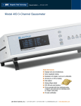
1
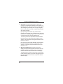
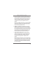
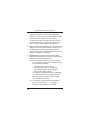
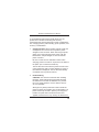
User’s User’s Manual Manual Model 410 Gaussmeter LakeShore Methods and apparatus disclosed and described herein have been developed solely on company funds of Lake Shore Cryotronics, Inc. No government or other contractual support or relationship whatsoever has existed which in any way affects or mitigates proprietary rights of Lake Shore Cryotronics, Inc. in these developments. Methods and apparatus disclosed herein may be subject to U.S. Patents existing or applied for. Lake Shore Cryotronics, Inc. reserves the right to add, improve, modify, or withdraw functions, design modifications, or products at any time without notice. Lake Shore shall not be liable for errors contained herein or for incidental or consequential damages in connection with furnishing, performance, or use of this material. Revision 1.3 P/N 119-002 11 May 2004 Model 410 Gaussmeter User’s Manual LIMITED WARRANTY STATEMENT – WARRANTY PERIOD: ONE (1) YEAR 1. Lake Shore warrants that this Lake Shore product (the “Product”) will be free from defects in materials and workmanship for the Warranty Period specified above (the “Warranty Period”). If Lake Shore receives notice of any such defects during the Warranty Period and the Product is shipped freight prepaid, Lake Shore will, at its option, either repair or replace the Product if it is so defective without charge to the owner for parts, service labor or associated customary return shipping cost. Any such replacement for the Product may be either new or equivalent in performance to new. Replacement or repaired parts will be warranted for only the unexpired portion of the original warranty or 90 days (whichever is greater). 2. Lake Shore warrants the Product only if it has been sold by an authorized Lake Shore employee, sales representative, dealer or original equipment manufacturer (OEM). 3. The Product may contain remanufactured parts equivalent to new in performance or may have been subject to incidental use. 4. The Warranty Period begins on the date of delivery of the Product or later on the date of installation of the Product if the Product is installed by Lake Shore, provided that if you schedule or delay the Lake Shore installation for more than 30 days after delivery the Warranty Period begins on the 31st day after delivery. 5. This limited warranty does not apply to defects in the Product resulting from (a) improper or inadequate maintenance, repair or calibration, (b) fuses, software and non-rechargeable batteries, (c) software, interfacing, parts or other supplies not furnished by Lake Shore, (d) unauthorized modification or misuse, (e) operation outside of the published specifications or (f) improper site preparation or maintenance. 6. To the extent allowed by applicable law, the above warranties are exclusive and no other warranty or condition, whether written or oral, is expressed or implied. Lake shore specifically disclaims any implied warranties or conditions of merchantability, satisfactory quality and/or fitness for a particular purpose with respect to the product. Some countries, states or provinces do not allow limitations on an implied warranty, so the above limitation or exclusion might not apply to you. This warranty gives you specific legal rights and you might also have other rights that vary from country to country, state to state or province to province. 7. To the extent allowed by applicable law, the remedies in this warranty statement are your sole and exclusive remedies. 8. Except to the extent prohibited by applicable law, in no event will lake shore or any of its subsidiaries, affiliates or suppliers be liable for direct, special, incidental, consequential or other damages (including lost profit, lost data or downtime costs) arising out of the use, inability to use or result of use of the product, whether based in warranty, contract, tort or other legal theory, and whether or not lake shore has been advised of the possibility of such damages. Your use of the Product is entirely at your own risk. Some countries, states and provinces do not allow the exclusion of liability for incidental or consequential damages, so the above limitation may not apply to you. 9. Except to the extent allowed by applicable law, the terms of this limited warranty statement do not exclude, restrict or modify, and are in addition to, the mandatory statutory rights applicable to the sale of the product to you. Copyright © 1993, 1996, 1997, 1999, 2003 and 2004 by Lake Shore Cryotronics, Inc. All rights reserved. No portion of this manual may be reproduced, stored in a retrieval system, or transmitted, in any form or by any means, electronic, mechanical, photocopying, recording, or otherwise, without the express written permission of Lake Shore. A Model 410 Gaussmeter User’s Manual INTRODUCTION The Model 410 Gaussmeter is a hand-held, field-portable unit that measures AC and DC magnetic fields. The unit is designed for wide range, high accuracy, and ease of use. User interface is via front panel keys and a custom liquid crystal display (LCD). Most user features are one pushbutton away. The Model 410 is provided in one of four configurations: Model 410-SCT in a soft case with a transverse probe. Model 410-SCA in a soft case with an axial probe. Model 410-SCAT in a soft case with axial and transverse probe. Model 410-HCAT in a hard case with axial and transverse probe. Although the Model 410 is water resistant, it is not waterproof. Under no circumstances should the unit be immersed in water or subjected to continuous high-humidity conditions. This manual contains information about instrument specifications, accessories, options, front panel, front panel controls, axial and transverse probes, initial setup, operation, probe considerations, and what to do in case of trouble. 1 Model 410 Gaussmeter User’s Manual SPECIFICATIONS * Display: LCD, 3½ digits; Update Rate: 2.5 times/second Resolution: 0.1 gauss (200 gauss range) DC Accuracy: 2% of reading ±0.1% of full scale at 25 °C (Including instrument, probe, and a calibration transfer) AC Accuracy: ±5% of reading Frequency Response: DC and 20 Hz. to 10 kHz. Three Ranges: ±200.0 G (±20.00 mT) ±2.000 kG (±200 mT) ±20.00 kG (±2.000 T) Temperature Range: 0 to 50 °C (Operating) Instrument Temperature Coefficient: 0.05% of reading per °C Instrument and Probe Temperature Coefficient: 0.1% of reading per °C Weight: 0.45 kilograms (1 pound) Size: 19.3 × 9.9 × 4.32 cm (7.6 × 3.9 × 1.7 in.) Power: Battery Operated; 4 AA (life >160 hours) Other Features: Max Hold, Relative Reading Mode, Alarm, Filter, settings retained in memory on power down, and water-resistant enclosure. * Lake Shore certifies that this product has been inspected and tested in accordance with its published specifications and that this product met its published specifications at the time of shipment. The accuracy and calibration of this product at the time of shipment are traceable to the United States National Institute of Standards and Technology (NIST); formerly known as the National Bureau of Standards (NBS), or to a recognized natural standard. 2 Model 410 Gaussmeter User’s Manual ACCESSORIES The Gaussmeter is provided with the following accessories: 1. Carrying Case. A soft or hard case is provided, depending on the model ordered. 2. Choice of Transverse Probe (senses magnetic fields perpendicular to probe axis), Axial Probe (senses magnetic fields parallel to probe axis), or both, depending on the model ordered. 3. Model MPEC-410-3 Probe Extension Cable. Allows probe to be extended 1 meter (3 feet) from unit. 4. Model 4106. Set of 4 “AA” Batteries. 5. User’s Manual. OPTIONS The following options are also available for the Model 410 Gaussmeter. 1. Model 4060 Zero Gauss Chamber. Small chamber in which to place tip of probe to eliminate background magnetic fields. 2. Model MPEC-410-10 Probe Extension Cable. Allows probe to be extended 3 meters (10 feet) from unit. 3. Model 4107 Bench Support. Allows Model 410 to be used on the bench top. 3 Model 410 Gaussmeter User’s Manual FRONT PANEL The Model 410 Gaussmeter front panel is shown in Figure 1. The top connector is the probe connector. AC Range Gauss/ Tesla 7 8 9 DC Relative Filter 4 5 6 Max Hold Max Reset Cal. No. 1 2 3 Zero Probe Alarm On/Off Alarm Point 0 Escape Power Off Power On Enter +/ 410 Gaussmeter Figure 1. Model 410 Front Panel 4 Model 410 Gaussmeter User’s Manual FRONT PANEL CONTROLS The Model 410 Gaussmeter front panel keys are defined as follows. Segments of the LCD are activated to reflect user selected operating modes. ON Turns power to the unit on. OFF Turns power to the unit off. AC Selects AC (periodic) magnetic field measurement. DC Selects DC (static) magnetic field measurement. Gauss/Tesla Changes units from gauss to tesla. Gauss is used in the cgs system: 1 G = 10–4 T. Tesla is used in the SI system: 1 T = 104 G. Range Push to select the field measurement range. If the user has selected Gauss as the units, pressing the Range key toggles the display between 200 Gauss (G), 2 kilogauss (kG), 20 kG full scale, and Auto Range. If the user has selected Tesla, pressing the Range key will toggle the display between 20 millitesla (mT), 200 mT, 2 tesla (T), and Auto Range. Max Hold Turns Max Hold feature on and off. Max Hold captures and displays the highest field reading. Use Max Reset key to clear reading. (Max Hold is not designed to capture instantaneous peaks and should not be confused with Peak Hold.) Max Reset Works with the Max Hold function. Resets the Max reading back to zero to capture the next max reading. 5 Model 410 Gaussmeter User’s Manual Front Panel Controls (Continued) Relative Best described as a user entered offset. This key captures the field reading as the relative setpoint, then displays the positive or negative deviation from that setpoint. The relative feature is often used to offset large magnetic fields. The relative feature can also be used with the Max Hold and Alarm features. Filter Toggles between an immediate display (no Filter), or an average display of the last 8 readings (Filter on). This feature makes the display more stable by averaging out the noise. Alarm On/Off Toggles between Alarm On and Alarm Off. The alarm is activated whenever the magnitude of the magnetic field exceeds the alarm point—regardless of the polarity (positive or negative). Alarm Point 6 When pushed, the unit will display the current alarm point. If this number is acceptable, push the Enter key. If another alarm point is desired, then enter another number using the numerical keypad. If the new alarm point is in a different range, then escape Alarm Point, set the range, then return to Alarm Point. When the alarm point is exceeded, an audible alarm inside the unit will sound and the Alarm indicator will flash. Push the Alarm On/Off key to turn the alarm off. Model 410 Gaussmeter User’s Manual Front Panel Controls (Continued) Zero Probe Used to zero or null effects of ambient low level fields from the probe. When the user pushes the Zero Probe key, Zero Probe and “– – –” are displayed. The user may then press either Enter or the Zero Probe key again to begin the zero probe routine. The unit then automatically accepts whatever residual field it reads as a zero offset, forcing the display to zero. Cal No. When the unit is first turned on, the Calibration Number of the probe last entered is displayed. (Every probe has a unique number assigned to it. The number is located on the base of the probe.) If the number is correct, i.e., the same probe is still mounted to the unit, press the Enter or Escape key to accept the current display. If the Calibration number does not match, use the appropriate number keys to enter the 2-, 3-, or 4-digit number, followed by the Enter key. Enter Used to accept the numbers displayed during numerical entry. Escape The Escape key is used to terminate a function (like Alarm or Cal No.) without making changes to the existing settings. The unit will then return to normal operation. LOW BATT The LOW BATT indicator will come on when the batteries begin to reach the end of their useful life. Readings may not be as accurate when the batteries get low. 7 Model 410 Gaussmeter User’s Manual AXIAL AND TRANSVERSE PROBES The Model 410 Gaussmeter can use either the axial or transverse probe shown in Figure 2. Flux Density 4.4 mm (0.175") Flux Density 2.3 mm (0.09") Max. 27.9 ±1.5 mm (1.1 ±0.06") 27.9 ±1.5 mm (1.1 ±0.06") 66.0 ±6.4 mm (2.6 ±0.25") 114.3 ±6.4 mm (4.5 ±0.25") 4.4 mm (0.175") 1.52 mm (0.06") Max. 66.0 ±6.4 mm (2.6 ±0.25") 3.2 mm (0.125") Nominal diameter flexible stem Transverse Probe Model MST-410 114.3 ±6.4 mm (4.5 ±0.25") 3.2 mm (0.125") Nominal diameter flexible stem Axial Probe Model MSA-410 Figure 2. Axial and Transverse Probes 8 Model 410 Gaussmeter User’s Manual INITIAL SETUP Initial setup of the Model 410 Gaussmeter is defined as follows. 1. Install Batteries. Remove two Phillips-head screws from rear door of Model 410. Be careful not to lose or damage rubber washers under the screwheads. Remove door. Do not lose or damage the rubber gasket inside battery door. Install 4 “AA” Batteries observing the polarity signs for each cell inside the battery compartment. Replace battery door. 2. Select Probe. The Model 410 uses either Transverse and Axial probes. The Transverse probe has the Hall sensor mounted parallel to the probe axis and measures magnetic fields perpendicular to the probe axis. See figure below. Hall Sensor Transverse Probe Top View Measures Flux Density Perpendicular To Probe Axis Transverse Probe Side View The Axial probe has the Hall sensor mounted perpendicular to the probe axis and measures magnetic fields parallel to the probe axis. See the figure at the top of the next page. 9 Model 410 Gaussmeter User’s Manual Initial Setup (Continued) Hall Sensor Measures Flux Density Parallel To Probe Axis Axial Probe Top View 3. Install Probe. Plug the probe into the center connector at the top of the Gaussmeter. If the extension cable is used, plug the probe into the cable end. The probe connector is keyed so that when installed, the Cal No. faces the user. To remove probe or extension cable, push the black button on the front of the connector and pull away from unit. Do not twist. 4. Turn On Instrument. Push the Power On key. The LCD displays all annunciators, then the current Calibration Number, and then returns to the state it was in before being turned off. 5. Calibrate Probe to Meter. Push the Cal. No. key. If the Calibration number shown on the display matches the number on the probe, press the Enter key and proceed to Operation. If the Calibration number does not match, use the appropriate number keys to enter the 2-, 3-, or 4-digit number, followed by the Enter key. To verify you have entered the correct number, press the Cal. No. key again, check the number, then press the Enter key. 10 Model 410 Gaussmeter User’s Manual OPERATION Operation of the Model 410 is defined as follows. 1. Turn On Meter. Push the Power On key. The LCD displays all annunciators, the current Calibration Number, and then the display returns to the state it was in before being turned off. 2. Gauss/Tesla. Field values are displayed in gauss (G) or tesla (T). Press the Gauss/Tesla key to toggles the display between the two units. The relation between gauss and tesla is 1 G = 0.0001 T, or 1 T = 10,000 G. When field units are changed, relative and alarm setpoints are converted to the new units with no interruption in operation. When tesla is selected, the Model 410 displays AC or DC field values followed by T for tesla or mT for millitesla. When gauss is selected, the Model 410 displays AC or DC field values followed by kG for kilogauss or G for gauss. 3. Select Range. If gauss ia selected, press the Range key to toggle the display between 200 G, 2 kG, 20 kG, and Auto Range. If tesla is selected, pressing the Range key toggles between 20 mT, 200 mT, 2 T, and Auto Range. In Auto Range mode, the Model 410 selects the range with the best resolution for the field being measured. It can take up to 2 seconds for Auto Range to work, so manual ranging may be better in some conditions. Auto Ranging should not be used when measuring small fields in a large background field, i.e., measuring a small DC field in presence of a large AC field, or measuring a small AC field in the presence of a large DC field. 11 Model 410 Gaussmeter User’s Manual Operation (Continued) 4. Zero Probe. The zero probe function is used to null (cancel) out small magnetic fields and probe offsets. For the Model 410, the zero probe routine is normally initiated while holding the probe away from any major magnetic field, but may also be used with the optional Model 4060 Zero Gauss Chamber. Upon pushing the Zero Probe key, the Zero Probe indicator in the LCD will come on. Remove the probe from the presence of any large magnetic field. Then push Enter or the Zero Probe key again to initiate zeroing. To zero the probe in the optional Zero Gauss Chamber, press Zero Probe, carefully place the probe tip into the chamber, and press Zero Probe again. Orientation of the probe is not critical. Do not move the probe while calibrating. For best results, periodic zeroing of the probe is recommended. Users wishing to cancel large magnetic fields should use the Relative function. 5. Max Hold and Max Reset. The Max Hold function displays the largest field magnitude measured since the last Max Reset. When the Max Hold key is pressed, the maximum value is captured and shown in the display. The Max Reset key clears the hold value. The hold value is also reset upon power up or when changing from AC or DC. Max Hold may also be used in conjunction with the Relative display. 12 Model 410 Gaussmeter User’s Manual Operation (Continued) In AC or DC operation, the Max Hold feature holds the field reading that is largest in magnitude. This is intended to monitor slowly changing signals. A field change not visible on the display cannot be recorded in Max Hold. The display shows only the magnitude of the max. reading. Reasons to use Max Hold include: (1) to capture readings in hard to get at places, and (2) to display the maximum field when field orientation is unknown. It is also useful when measuring high gradient fields. 6. Relative. The relative function lets the user see small variations in larger fields. The setpoint (or center) of the relative reading is captured when you press the Relative key—nulling the present field. The plus or minus deviation from that setpoint is then displayed.When Relative and Max Hold functions are used at the same time, only the maximum deviation from the setpoint is displayed. 7. Alarm On/Off and Alarm Point. The alarm gives an audible and visual indication of when the field is greater than a user specified value. The alarm is activated whenever the displayed field exceeds the alarm point— regardless of the sign (positive or negative) of the reading. Before using the alarm function, the user must define the Alarm Point. When the Alarm Point key is initially pushed, the unit will display the current alarm point. If this number is acceptable, push the Enter or Escape key. If another alarm point is desired, then enter another number using the numerical keypad. 13 Model 410 Gaussmeter User’s Manual Operation (Continued) When the alarm point is exceeded, an audible alarm inside the unit will sound and the Alarm indicator will flash. Push the Alarm On/Off key to turn the alarm off. To change the range of the alarm point, the user must first exit the alarm point, change to the desired range, return to Alarm Point, and begin to enter numbers. 8. Filter. The filter function averages several sequential field readings. It is used to quiet the display, making it more readable when the probe is exposed to a noisy field. Filtering should not be used with Max Hold since it slows reaction to changes in the field value. 9. Keypad Lock. The keypad lock prevents accidental changes from being made to the setup. Use the following procedure to activate the Keypad Lock. (a) Press and hold the Enter key for 10 seconds until “LLL” is displayed. All changes to settings are locked out, except for the following: • • • • • The Alarm can be turned on and off. The current Alarm Point can be displayed. The Calibration Number can be displayed. Power can be turned on and off. Pressing and holding the Escape key will display the software date, but the unit will not be reset. If the user attempts to make any other changes, “LLL” is displayed on the LCD. (b) To unlock the unit, press and hold the Enter key again for 10 seconds until “- - -” is displayed. Changes to settings will then be accepted. 14 Model 410 Gaussmeter User’s Manual PROBE CONSIDERATIONS To avoid damage and for best results during use, the probes have a number of handling and accuracy requirements that must be observed. These considerations are: changing probes, probe handling, probe operation, and accuracy considerations. 1. Changing Probes. When inserting a probe, grasp the metal part of the connector and to push the probe straight into the connector. When removing the probe, grasp only on the metal part of the probe, push the black button, and pull straight out. Do not twist the probe connector. Be sure to enter the new calibration number when changing probes. The Cal No. is printed on the label on the probe. (Do not enter the Serial No.) The unit will not function with the probe removed. If the unit is powered up with no probe attached, a series of three dashes is displayed. The unit will automatically re-initialize when a probe is inserted. 2. Probe Handling CAUTION: Care must be exercised when handling the probe. The tip of the probe is very fragile. Stressing the Hall sensor can alter its calibration. Any excess force can easily break the sensor. Broken sensors are not repairable. Although every attempt has been made to make the probes as sturdy as possible, they are still fragile. The probe should only be held in place by securing at the handle. The probe stem should never have force applied. Excessive force may destroy the Hall sensor. 15 Model 410 Gaussmeter User’s Manual Probe Handling (Continued) The axial sensor is exposed on the end of the probe. A collision with a hard surface can damage the sensor or wear away its protective coating. The transverse sensor is more protected, but is somewhat susceptible to bending stress and erosion of the protective coating. As a rule, the stem should not be bent more than 45° from the base. See Figure 3. Force should never be applied to the tip of the probe. On all probes, do not pinch or allow cables to be struck by any heavy or sharp objects. Damaged probes are not repairable. When the gaussmeter is not in use, the probes should be stored separately in the supplied protective tubes. Do not bend from tip of probe Sensor Substrate Hall Effect Sensor 45° 45° Stem Flexible Probe Maximum Bend Angle Figure 3. Maximum Flexible Probe Bend Radius 16 Model 410 Gaussmeter User’s Manual 3. Probe Operation NOTE: For best results, the instrument and probe should warm up for at least 5 minutes before operation If used, the optional Zero Gauss Chamber and probe should be at the same temperature. In the DC mode of operation, the orientation of the probe affects the polarity reading of the gaussmeter. On a transverse probe, the black button on the connector indicates the side for positive (+) flux entry. On an axial probe, positive (+) flux entry is always from the front of the probe. See Figure 4. N S S Black Button Indicates Positive Polarity Transverse Probe Orientation For Positive (+) Measurement N Axial Probe Orientation For Positive (+) Measurement Figure 4. Probe Orientation For Positive Measurement 17 Model 410 Gaussmeter User’s Manual Probe Operation (Continued) If the exact direction of the magnetic field is unknown, its orientation is determined by slowly rotating the probe. As the probe turns, the measured field rises and falls. Make note of the probe orientation at the maximum reading to identify the field direction. 4. Probe Accuracy Considerations NOTE: Probe readings are dependent upon the angle of the sensor in relation to the magnetic field. The further from 90° the angle between the probe and the field, the greater the percentage of error, e.g., a 5° deviation causes a 0.4% error, a 10° deviation causes a 1.5% error, etc. NOTE: For best results, the instrument and probe should warm up for at least 5 minutes before operation. The probe and the zero gauss chamber should be at the same temperature. The user must consider all the possible contributors to the accuracy of the reading. Both the probe and gaussmeter have accuracy specifications that may affect the actual reading. The probe should be zeroed before making critical measurements. The zero probe function is used to null (cancel) out the zero offset of the probe or small magnetic fields. It is normally used in conjunction with the zero gauss chamber, but may also be used with a probe in a free condition (oriented for minimum Earth’s magnetic field effect). Users wishing to cancel out large magnetic fields should use the Relative function. 18 Model 410 Gaussmeter User’s Manual Probe Accuracy Considerations (Continued) Probe temperature can also affect readings. Refer to the specifications at the front of this manual. Probe readings are dependent on the angle of the sensor (Hall sensor) in relation to the magnetic field. Maximum output occurs when the flux vector is perpendicular to the plane of the sensor. This is the condition that exists during factory calibration. The greater the deviation from orthogonality (from right angles in either of three axes), the larger the error of the reading. For example, a 5° variance on any one axis causes a 0.4% error, a 10° misalignment induces a 1.5% error, etc. See Figure 5. 29.3% 45° +B 13.4% 6.0% 3.4% 1.5% 0.4% 0% Error 30° 20° 15° 10° 5° 0° Deviation from Perpendicular (G (G) Effect of angular variations on percentage of reading error where % Error = (1 cos G) 100 Figure 5. Effect Of Angle On Measurements 19 Model 410 Gaussmeter User’s Manual IN CASE OF TROUBLE In case of trouble with the Model 410, refer to the following instructions. 1. Software Revision Date. When talking to the factory, it is often necessary to know the revision date of the Model 410 operating software. Hold down the Escape key for 10 seconds. In the right-hand two digit spaces of the LCD, the software revision date will be displayed in DD, MM, YY sequence. 2. Instrument Reset. If you continue to hold the Escape key while the software revision date is being displayed, the unit will be reset. As soon as all the annunciators are displayed, let go of the Escape key. The instrument will be reset to the following defaults: Cal. No. 1000 20 kG Range DC All special functions off 3. 20 Error Code “E2.” If the internal non-volatile memory has failed, error code “E2” will be displayed for 3 seconds on power up, then the unit will return to the default settings listed above. The unit will still function, but user settings (including Calibration Number) will not be retained upon power down. If this error code should appear, please call Lake Shore Technical Service at (614) 891-2243, or e-mail at [email protected]. NOTES Lake Shore is a technology leader in the development of cryogenic temperature sensors, precision low temperature measurement and control instrumentation, and magnetic measurement and test systems. Since 1968, Lake Shore physicists, material scientists, and engineers have dedicated themselves to the development of tomorrow’s technology today. Lake Shore serves a worldwide network of Customers including university and national laboratories, as well as many of the premier companies around the world. Lake Shore Cryotronics, Inc. 575 McCorkle Boulevard Westerville, OH 43082-8888 USA Fax: (614) 891-1392 Phone: (614) 891-2243 E-Mail Addresses: [email protected] [email protected] Visit Our Website: www.lakeshore.com