Transcript
1. About the manual
1.1 MELSERVO MR-JN relevant manual
This installation guide explains how to mount MR-JN servo amplifiers.
If you have any questions about the operation or programming of the equipment described in this guide, contact your
local sales office.
In addition, when you mount a protective device, specific technical skills which are not detailed in the guide will be
required.
JN Series
MR-JN-10A/MR-JN-20A/MR-JN-40A
MR-JN-10A1/MR-JN-20A1
1.2 Purpose of this guide
This installation guide explains the safe operation of MR-JN servo amplifiers for engineers of machinery manufacturers
and machine operators. For detailed information of the products, refer to "MR-JN-_A Servo Amplifier Instruction
Manual".
2.5 Disposal
Disposal of unusable or irreparable devices should always occur in accordance with the applicable country-specific
waste disposal regulations. (Example: European Waste 16 02 14)
2. About safety
Installation direction and clearances
WARNING
CAUTION
H
Tel/Fax
Sales office
USA
(2) When mounting, installing, and using the MELSERVO MR-JN servo amplifier, always observe applicable
standards and directives in the country.
MITSUBISHI ELECTRIC AUTOMATION, INC.
500 Corporate Woods Parkway, Vernon Hills, IL 60061, U.S.A.
Tel : +1-847-478-2100
Fax : +1-847-478-2253
Germany
MITSUBISHI ELECTRIC EUROPE B.V. German Branch
Gothaer Strasse 8, D-40880 Ratingen, Germany
Tel : +49-2102-486-0
Fax : +49-2102-486-1120
China
MITSUBISHI ELECTRIC AUTOMATION (CHINA) LTD.
No.1386 Hongqiao Road, Mitsubishi Electric Automation Center, Changning District, Shanghai,
China
Tel : +86-21-2322-3030
Fax : +86-21-2322-3000
Korea
MITSUBISHI ELECTRIC AUTOMATION KOREA CO., LTD.
1480-6, Gayang-Dong, Gangseo-Gu, Seoul, 157-200, Korea
Tel : +82-2-3660-9510
Fax : +82-2-3664-8372/8335
Indicates that incorrect handling may cause hazardous conditions, resulting in death or severe injury.
CAUTION
Indicates that incorrect handling may cause hazardous conditions, resulting in medium or slight injury to
personnel or physical damage.
It takes 15 minutes for capacitor discharging. Do not touch the unit and terminals immediately
after power off.
MR-JN-10A(1)/MR-JN-20A(1)/MR-JN-40A
Note
75 °C/60 °C stranded wires [AWG]
(Note 1, 2)
P+/C
P/C
U/V/W/
14/14
(Note 3) 14/14
14/14
MR-JN-10A
MR-JN-20A/MR-JN-10A1
MR-JN-40A/MR-JN-20A1
Servo amplifier
L1/L2
Servo amplifier
MR-JN Servo amplifier Instructions and Cautions for Safe Use of AC Servos (this guide)
Quantity
1
1
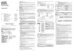
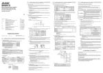
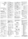
Rating plate
The following shows an example of rating plate for explanation of each item.
AC SERVO
SER.A45001001
MODEL MR-JN-10A
POWER : 100W
INPUT
: AC200-230V 1.5A 50/60Hz, DC24V 0.5A
OUTPUT: 3PH170V 0-360Hz 1.1A
STD.: IEC/EN 61800-5-1
MAN.: IB(NA)0300157
Max. Surrounding Air Temp.: 55°C
IP20
KCC-REI-MEK-TC300A566G51
DATE: 2014-05
TOKYO 100-8310, JAPAN
Warning plate
・
MADE IN JAPAN
・
・
・
・
・
・
・
・
・
・
・
・
・
・
・
・
・
・
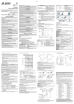
Rated output
Symbol Rated output [W]
10
100
20
200
40
400
Hardware special specification
Blank or 2 to 5 digit alphanumeric
(RJ, ED, PX, RU, RZ, etc.)
General-purpose interface
(1) Installation
The minimum cabinet size is 150% of the MR-JN servo amplifier's volume. Also, design the cabinet so that the
ambient temperature in the cabinet is 55 °C or less. The servo amplifier must be installed in a metal cabinet.
Additionally, mount the servo amplifier on a cabinet that the protective earth based on the standard of IEC/EN
60204-1 is correctly connected. For environment, the units should be used in open type (UL 50) and overvoltage
category shown in table in section 8.1. The servo amplifier needs to be installed at or below of pollution degree 2.
For connection, use only copper wires.
(2) Short-circuit current rating (SCCR)
Suitable For Use On A Circuit Capable Of Delivering Not More Than 100 kA rms Symmetrical Amperes, 500 Volts
Maximum.
(3) Overload protection characteristics
The MR-JN servo amplifiers have servo motor overload protective function. (It is set on the basis (full load current)
of 120% rated current of the servo amplifier.)
(4) Over-temperature protection for motor
Motor Over temperature sensing is not provided by the drive.
Integral thermal protection(s) is necessary for motor. Refer to chapter 4 for details of the proper connections.
(5) Branch circuit protection
For installation in the United States, branch circuit protection must be provided, in accordance with the National
Electrical Code and any applicable local codes.
For installation in Canada, branch circuit protection must be provided, in accordance with the Canada Electrical
Code and any applicable provincial codes.
2.3.4 South Korea compliance
This product complies with the Radio Wave Law (KC mark). Please note the following to use the product.
이 기기는 업무용 (A급) 전자파적합기기로서 판 매자 또는 사용자는 이 점을 주의하시기 바라며,가정외의
지역에서 사용하는 것을 목적으 로 합니다.
(The product is for business use (Class A) and meets the electromagnetic compatibility requirements. The seller and the
user must note the above point, and use the product in a place except for home.)
Side
W
D
a1
The control circuit connectors described by rectangles are safely separated from the main circuits described by circles.
The connected motors will be limited as follows.
c
HF-KN/HF-KP series servo motors (Mfg.: Mitsubishi Electric)
b
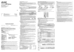
5. Signals
c
The following shows CN1 connector signals as a typical example. For the other connector details, refer to "MR-JN-_A
Servo Amplifier Instruction Manual".
MR-JN-10A(1)/MR-JN-20A(1)
MR-JN-40A
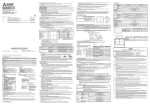
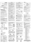
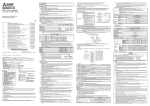
Variable dimension table [mm]
W
H
D
40
130
135
50
130
135
Mass [kg]
0.6
0.7
Servo amplifier
d
MR-JN-10A(1)/MR-JN-20A(1)
MR-JN-40A
a
5.5
6
Variable dimensions [mm]
a1
b
5.5
120 ± 0.5
6
120 ± 0.5
c
5
5
Screw size
d
M5
M5
a
CN1
[Warranty]
14
1
OPC
4
SON
8
2.3.3 USA/Canada compliance
This servo amplifier is designed in compliance with UL 508C and CSA C22.2 No.14.
Front
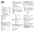
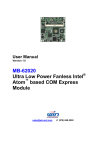
Note. Please use a thermal sensor, etc. for thermal protection of the servo motor.
10
INP
12
MBR
DICOM
3
RES
5
CR
7
LSN
9
ALM
11
RD
13
15
LA
17
LB
19
LZ
21
OP
23
PP
25
NP
LG
16
LAR
18
LBR
20
LZR
22
PG
24
NG
26
This is in position control mode.
6. Maintenance and service
1. Warranty period and coverage
We will repair any failure or defect hereinafter referred to as "failure" in our FA equipment hereinafter referred to as the
"Product" arisen during warranty period at no charge due to causes for which we are responsible through the distributor from
which you purchased the Product or our service provider. However, we will charge the actual cost of dispatching our engineer
for an on-site repair work on request by customer in Japan or overseas countries. We are not responsible for any on-site
readjustment and/or trial run that may be required after a defective unit are repaired or replaced.
[Term]
The term of warranty for Product is twelve (12) months after your purchase or delivery of the Product to a place designated by
you or eighteen (18) months from the date of manufacture whichever comes first ("Warranty Period"). Warranty period for
repaired Product cannot exceed beyond the original warranty period before any repair work.
[Limitations]
(1) You are requested to conduct an initial failure diagnosis by yourself, as a general rule. It can also be carried out by us or our
service company upon your request and the actual cost will be charged. However, it will not be charged if we are responsible
for the cause of the failure.
(2) This limited warranty applies only when the condition, method, environment, etc. of use are in compliance with the terms and
conditions and instructions that are set forth in the instruction manual and user manual for the Product and the caution label
affixed to the Product.
(3) Even during the term of warranty, the repair cost will be charged on you in the following cases.
(i)
a failure caused by your improper storing or handling, carelessness or negligence, etc., and a failure caused by your hardware or software
problem
(ii) a failure caused by any alteration, etc. to the Product made on your side without our approval
(iii) a failure which may be regarded as avoidable, if your equipment in which the Product is incorporated is equipped with a safety device
required by applicable laws and has any function or structure considered to be indispensable according to a common sense in the industry
(iv) a failure which may be regarded as avoidable if consumable parts designated in the instruction manual, etc. are duly maintained and
replaced
(v) any replacement of consumable parts (battery, fan, smoothing capacitor, etc.)
(vi) a failure caused by external factors such as inevitable accidents, including without limitation fire and abnormal fluctuation of voltage, and
acts of God, including without limitation earthquake, lightning and natural disasters
(vii) a failure generated by an unforeseeable cause with a scientific technology that was not available at the time of the shipment of the Product
from our company
(viii) any other failures which we are not responsible for or which you acknowledge we are not responsible for
2. Term of warranty after the stop of production
Surge protector: Okaya Electric Industries RSPD-250-U4 series
Power supply
Symbol
Power supply
None 1-phase 200 V AC to 230 V AC
1
1-phase 100 V AC to 120 V AC
24 V DC
24 V DC
Sine-wave PWM control, current control method
2 (IEC/EN 60664-1)
III (IEC/EN 60664-1)
I (IEC/EN 61800-5-1)
100 kA
Encoder
EM1
(2) For Declaration of Conformity (DoC)
Hereby, MITSUBISHI ELECTRIC EUROPE B.V., declares that the servo amplifiers are in compliance with the
necessary requirements and standards (2004/108/EC and 2006/95/EC). For the copy of Declaration of Conformity,
contact your local sales office.
MR-JN-10A1/MR-JN-20A1
1-phase 100 V AC to 120 V AC, 50 Hz/60 Hz
Cabinet side
DOCOM
Software special specification
Blank, Jn, Sn, or Un
(n = 00 to 999)
H
Machine side
PE terminals
MR-JN servo amplifiers are not intended to be used on a low-voltage public network which supplies domestic
premises; Radio frequency interference is expected if it is used on such a network. The installer shall provide a
guide for installation and use, including recommended mitigation devices.
MR-JN-10A/MR-JN-20A/MR-JN-40A
1-phase 200 V AC to 230 V AC, 50 Hz/60 Hz
8.3 Mounting hole
(1) EMC requirement
MR-JN servo amplifiers comply with category C3 in accordance with IEC/EN 61800-3. Install an EMC filter and
surge protector on the primary side of the servo amplifier. As for I/O signal wires (max. length 10 m) and encoder
cables (max. length 50 m), use shielded wires and ground the shields. The following shows recommended
products.
Model
The following describes what each block of a model name
indicates. Not all combinations of the symbols are available.
Series
U/V/W/PE
Servo motor
LSP
EMC filter: Soshin Electric HF3000A-UN series
Item
Main circuit (line
voltage)
Control circuit
Interface (SELV)
Control method
Pollution degree
Overvoltage category
Protective class
Short-circuit current rating (SCCR)
Power
supply
Servo amplifier
Encoder cable
6
PE terminals
8.1 MR-JN servo amplifier
Controller
CN2
(3) Power supply
This servo amplifier can be supplied from star-connected supply with grounded neutral point of overvoltage
category set forth in IEC/EN 60664-1 and shown in the table of section 8.1. However, when you use the neutral
point for single phase supply, a reinforced insulating transformer is required in the power input section. For the
interface power supply, use an external 24 V DC power supply with reinforced insulation on I/O terminals.
(4) Grounding
To prevent an electric shock, always connect the protective earth (PE)
terminal (marked
) of the servo amplifier to the protective earth (PE) of
the cabinet. Do not connect two grounding cables to the same protective
earth (PE) terminal. Always connect cables to the terminals one-to-one.
If using an earth-leakage current breaker, always ground the protective
earth (PE) terminal of the servo amplifier to prevent an electric shock.
This product can cause a DC current in the protective earthing conductor.
To protect direct/indirect contact using an earth-leakage current breaker
(RCD), only an RCD of type B can be used for the power supply side of
the product.
Operation, storage
Transportation
Altitude
8.2 Servo amplifier dimensions
CN1
2.3.2 EU compliance
The MR-JN servo amplifiers are designed to comply with the following directions to meet requirements for mounting,
using, and periodic technical inspections: EMC directive (2004/108/EC) and Low-voltage directive (2006/95/EC).
Serial number
Model
Capacity
Applicable power supply
Rated output current
Standard, Manual number
Ambient temperature
IP rating
KC certification number
The year and month of manufacture
Country of origin
・
24 V
0V
B1/B2
Fuse (300 V)
10 A
15 A
20 A
Operation
Transportation (Note)
Storage
8. Technical data
2
Contents of the package
Unpack the product and check the rating plate to see if the servo amplifier is as you ordered.
Contents
Molded-case circuit breaker (240 V AC)
NF50-SVFU-5A (50 A frame 5 A)
NF50-SVFU-10A (50 A frame 10 A)
NF50-SVFU-15A (50 A frame 15 A)
5 %RH to 90 %RH
10 Hz to 57 Hz with constant amplitude of 0.075 mm
57 Hz to 150 Hz with constant acceleration of 9.8 m/s2 to IEC/EN 61800-5-1 (Test Fc of IEC
60068-2-6)
5.9 m/s2
Class 2M3 (IEC/EN 60721-3-2)
Class 1M2 (IEC/EN 60721-3-2)
2
IP20 (IEC/EN 60529)
Open type (UL 50)
1000 m or less above sea level
10000 m or less above sea level
Note. In regular transport packaging
CN3
To protective equipment
(Thermal signal) (Note)
Vibration
resistance
Environment
0 to 55 Class 3K3 (IEC/EN 60721-3-3)
-20 to 65 Class 2K4 (IEC/EN 60721-3-2)
-20 to 65 Class 1K4 (IEC/EN 60721-3-1)
[°C]
[°C]
[°C]
IP rating
CAUTION
16/16
Ambient
humidity
Item
Operation
Transportation (Note)
Storage (Note)
Operation, transportation,
storage
Pollution degree
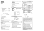
The following shows representative configuration examples to conform to the IEC/EN/UL/CSA standards.
AC/DC
converter
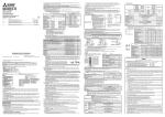
1. Select wire sizes depending on the rated output of the servo motors. The values in the table are sizes based on the rated output of the
servo amplifiers.
2. The following shows the PE terminal specifications of the servo amplifier.
Screw size: M4
Tightening torque: 1.2 [N•m]
Recommended crimp terminal: R2-4 (JST)
Crimping tool: YPT-60-21 (JST)
3. To wire with the servo motor, use LE-CSM (option). To extend the wiring, use the AWG14 wire size.
Servo amplifier
Copyright©2009 Mitsubishi Electric Corporation All Right Reserved.
Servo amplifier
Connecting a servo motor of the wrong axis to U, V, W, or CN2 of the servo amplifier may cause
a malfunction.
MCCB
or fuse
(2) Selection example of MCCB and fuse
Use a fuse (T class) or the molded-case circuit breaker (UL489 Listed MCCB) indicated in the table below. The T
class fuses and molded-case circuit breakers in the table are selected examples based on rated I/O of the servo
amplifiers. When you select a smaller capacity servo motor to connect it to the servo amplifier, you can also use
smaller capacity T class fuses or molded-case circuit breaker than ones in the table. For selecting ones other than
Class T fuses and molded-case circuit breakers below, refer to "MR-JN-_A Servo Amplifier Instruction Manual".
This guide uses recycled paper.
Specifications are subject to change without notice.
10 mm
or more
Turn off the molded-case circuit breaker (MCCB) to avoid electrical shocks or damages to the
product before starting the installation or wiring.
Recommended wire
Printed in Japan
10 mm
or more
Ambient
temperature
Test condition
WARNING
(1) Local wiring
Use only copper wires for wiring. The following table shows the stranded wires [AWG] rated at 75 °C/60 °C.
(Note 2)
L1/L2/L3/
14/14
80 mm or longer
for wiring
Bottom
Power supply
IB(NA)0300157-H(1407)MEE
40 mm
or more
Cabinet
40 mm
or more
2.3.1 Selection of peripheral equipment and wire
The followings are selected based on IEC/EN 61800-5-1, UL 508C, and CSA C22.2 No.14.
Servo amplifier
Top
4. Electrical Installation and configuration diagram
2.3 Correct use
Always use the MR-JN servo amplifiers within specifications (voltage, temperature, etc. Refer to "MR-JN_A Servo
Amplifier Instruction Manual" for details.). Mitsubishi Electric Co. accepts no claims for liability if the equipment is used in
any other way or if modifications are made to the device, even in the context of mounting and installation.
WARNING
HEAD OFFICE: TOKYO BLDG MARUNOUCHI TOKYO 100-8310
Cabinet
The devices must be installed in the
specified direction. Not doing so may
cause a malfunction.
Mount the servo amplifier on a cabinet
which meets IP54 in the correct vertical
direction to maintain pollution degree 2.
2.1 Professional engineer
Only professional engineers should mount MR-JN servo amplifiers.
Persons who took a proper engineering training or qualified persons who are engaged in electrical equipment.
Check if applicable technical training is available at your local Mitsubishi Electric office. Contact your local sales office
for schedules and locations.
2.2 Applications of the device
MR-JN servo amplifiers comply with the following standards.
IEC/EN 61800-5-1, IEC/EN 61800-3
CAUTION
Transport the products correctly according to their mass.
Stacking in excess of the limited number of product packages is not allowed.
Install the servo amplifier and servo motor in a load-bearing place in accordance with "MR-JN_A Servo Amplifier Instruction Manual".
Do not get on or put heavy load on the equipment.
Do not hold the lead wire of the built-in regenerative resistor when transporting the servo
amplifier.
When you keep or use the product, please fulfill the following environment.
3. Mounting/dismounting
This chapter explains safety of users and machine operators. Please read the chapter carefully before mounting the
equipment. In this installation guide, the specific warnings and cautions levels are classified as follows.
Instructions and Cautions for
Safe Use of AC Servos
Country/Region
(1) Only qualified personnel and professional engineers should perform system installation.
Servo amplifier
General-Purpose AC Servo
7. Transportation and storage
2.4 General cautions for safety protection and protective measures
Observe the following items to ensure proper use of the MELSERVO MR-JN servo amplifiers.
WARNING
To avoid an electric shock, only qualified personnel should attempt inspections. For repair and
parts replacement, contact your local sales office.
6.1 Inspection items
It is recommended that the following points periodically be checked.
(1) Check servo motor bearings, brake section, etc. for unusual noise.
(2) Check the cables and the like for scratches or cracks. Perform periodic inspection according to operating
conditions.
(3) Check that the connectors are securely connected to the servo motor.
(4) Check that the wires are not coming out from the connector.
(6) Check for unusual noise generated from the servo amplifier.
(7) Check the servo motor shaft and coupling for connection.
6.2 Parts having service lives
Service lives of the following parts are listed below. However, the service life varies depending on operating methods
and environment. If any fault is found in the parts, they must be replaced immediately regardless of their service lives.
For parts replacement, please contact your local sales office.
Part name
3. Service in overseas countries
Our regional FA Center in overseas countries will accept the repair work of the Product. However, the terms and conditions of
the repair work may differ depending on each FA Center. Please ask your local FA center for details.
4. Exclusion of responsibility for compensation against loss of opportunity, secondary loss, etc.
Whether under or after the term of warranty, we assume no responsibility for any damages arisen from causes for which we are
not responsible, any losses of opportunity and/or profit incurred by you due to a failure of the Product, any damages, secondary
damages or compensation for accidents arisen under a specific circumstance that are foreseen or unforeseen by our company,
any damages to products other than the Product, and also compensation for any replacement work, readjustment, start-up test
run of local machines and the Product and any other operations conducted by you.
5. Change of Product specifications
Specifications listed in our catalogs, manuals or technical documents may be changed without notice.
(5) Check for dust accumulation on the servo amplifier.
Smoothing capacitor
Relay
(1) We may accept the repair at charge for another seven (7) years after the production of the product is discontinued. The
announcement of the stop of production for each model can be seen in our Sales and Service, etc.
(2) Please note that the Product (including its spare parts) cannot be ordered after its stop of production.
Life guideline
(Note) 10 years
Number of power-on times and forced stop times: 100,000 in total
Note. The characteristic of smoothing capacitor is deteriorated due to ripple currents, etc. The life of the capacitor greatly depends on ambient
temperature and operating conditions.
The capacitor will reach the end of its life in 10 years of continuous operation in normal air-conditioned environment (40 °C surrounding air
temperature or less).
6. Application and use of the Product
(1) For the use of our General-Purpose AC Servo, its applications should be those that may not result in a serious damage even if
any failure or malfunction occurs in General-Purpose AC Servo, and a backup or fail-safe function should operate on an
external system to General-Purpose AC Servo when any failure or malfunction occurs.
(2) Our General-Purpose AC Servo is designed and manufactured as a general purpose product for use at general industries.
Therefore, applications substantially influential on the public interest for such as atomic power plants and other
power plants of electric power companies, and also which require a special quality assurance system, including
applications for railway companies and government or public offices are not recommended, and we assume no
responsibility for any failure caused by these applications when used.
In addition, applications which may be substantially influential to human lives or properties for such as airlines,
medical treatments, railway service, incineration and fuel systems, man-operated material handling equipment,
entertainment machines, safety machines, etc. are not recommended, and we assume no responsibility for any
failure caused by these applications when used.
We will review the acceptability of the abovementioned applications, if you agree not to require a specific quality
for a specific application. Please contact us for consultation.