1
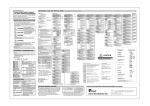
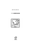
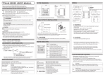
MTCTR/MTCTS
DIGITAL TEMPERATURE CONTROLLER
DIGITAL TEMPERATURE CONTROLLER
USER'S MANUAL
2007.3(The 1st edition)
*Thank you for purchasing Digital Temperature Controller. Please go through this Instruction Manual carefully
and use the unit in proper manner.
NOTICE/WARNING BEFORE OPERATION USE
The following symbol
is provided to prevent incident or damage. Kindly refer to the details of the
WARNING/CAUTION when using for the first time.
WARNING
Due to mishandling, serious dangers may occur to the operator such as death,
electrocution and a skin burn.
CAUTION
Due to mishandling, it may cause some damage to the unit or the operator
getting slight injury.
WARNING
●
●
Make sure the correct wiring connection before turning on electricity.
Miss-Wiring may cause malfunction of the unit and fire.
Never modify the unit to prevent damage or incident such as malfunction and fire etc.
CAUTION
● For prevention of its malfunction, do not push the front key with sharp points.
● Spare terminal must not be used for other purposes.
・Please put this user's manual aside for your reference, when operating the unit.
・Copy or reprint of this manual, wholly or partially, is not allowed.
・The contents of this manual may change without notice in future.
OPERATING ENVIRONMENT
Never use in the following environments. It may cause fire and break the wire.
1) Around explosive gases, inflammable gases or corrosive gases
2) In either sunshine or ambient temperature (above 50℃) remarkably increases
3) In very low ambient temperature (below 0℃), such as outdoors in cold areas
4) In very high humidity (85%RH or higher)
5) Around splashing of water or chemicals
6) Under severe vibration or shocks
7) Around dust, iron powder, black smoke
8) Around external noise, induction trouble, vibration, large shocks, and others such that can have damaging
effects to the electric circuit.
9) Under violent temperature change
SPECIFICATIONS
Type
MTCTR:Relay contact
Power Supply Voltage
100 to 240V AC, 50/60Hz
Power Consumption
Memory Element
Input of Sensor
Control Output
Control Method
Operation
Environment
Storage Environment
Weight
Location of the Unit
Setting
Below 10 VA
EEPROM
Thermocouple,R.T.D./0-5V,1-5V,4-20mA (Changeable by front key)
Relay contact, SSR drive voltage, Current
Two kinds of PID,ON/OFF
0 to 50℃,20 to 90%RH(Avoid making dew)
Installation condition
MTCTS:SSR drive voltage
-25 to 70℃,5 to 95%RH(Avoid making dew)
Less than 180g
Keep away from the followings.
・Gas of corrosion, dust and oily smoke.
・The electric noise of generator
・The influence of electromagnetic field.
・Mechanical vibration and shock.
・The direct sunlight.
Installation category Ⅱ
-1-
CAUTION BEFORE CONTROL
・Set-up program is stored operation, as non-volatile memory, is equipped with the controllers.
・Either thermocouple or R.T.D.(Pt 100/JPt100) is selectable input type, but Current/Voltage input needs to be
selected individually. For suitable application, please select most appropriate input type and adjust input setup.
(※Thermocouple at the time of shipment (K) )
・PID or ON/OFF control is selective for the optimal perform and each detail of features is specified in the table
below.
※PID constants are automatically calculated and written in, when control begins or SV is altered on self-tuning.
PID Control
ON/OFF Control
Merit
Better control result is achieved as Life span of relay is generally longer, as it is ON when SV and
opposed to that of ON/OFF control.
it is OFF when temperature is over SV (For heating control).
Demerit Life span of relay is shorter, as output Control value is worse in comparison with that of PID control.
exists frequently with relay contact.
PARTS INDICATION
Process value, character for setting
RDY
Lights ON under Ready
DI
Lights ON when DI turn ON
mode display.
MODE KEY
For change of display
OUT1
Lights ON when output 1 turn ON
FUNC KEY
For action of function setting
OUT2
Lights ON when output 2 turn ON
▲▼KEY
Holding the up down keys are the value at a
PV
mode display.
Setting value, input value for setting
SV
Up down key for change of setting value.
AL1
Lights ON when Event output 1 turn ON
AL2
Lights ON when Event output 2 turn ON
rapid rate.
part is not used.
※
Flash ON and OFF when communicating.
COM
Lights ON when communication is
selected as an option.
INSTALLTION AND WIRING
1)Outer Dimensions
60
48
77
2
59
48
Packing
Front
Case (black)
Attachment
2)Panel Cutout
A
A
60 or more
A
(48×No. of units−3)
A:45mm
-2-
tolerance:+0.6 -0
3)Wiring
EV2 (For alarm)
①
Relay output 250V AC
EV1 (For alarm)
⑥
2.4A(Load resistance)
⑪
Relay output
250V AC, 2.4A
(Load resistance)
⑫
OUT1
Relay output
250V AC, 3A
(Load resistance)
SSR drive voltage
12VDC output
②
③
+
−
①
⑥
⑪
②
⑦
⑫
③
⑧
⑬
④
⑨
⑭
⑤
⑩
⑮
②
③
Sensor Input
⑬bB
⑭B
⑮A
RTD
⑬−
⑭+
TC
POWER ON
100V to 240V AC 50/60Hz 10VA
(NO polarity)
AC100V∼240V 50∼60Hz 10VA
④
⑤
CAUTION
For prevention of electric shock, please connect wiring only
after turning power off and don’t touch the terminal part
when powered on.
PRECAUTIONS ON WIRE CONNECTION
1)
2)
3)
4)
5)
6)
When connecting wires, be sure to turn off the power supply in advance, or electric shock may result.
This unit will not perform control operation for approx. 4 seconds after turning on the power. Note this point
when using the unit as an interlock circuit, because no output is issued during this period.
Use the crimping terminal for wire connection that fits M3.5 thread.
(Tighten the wire directly at the center portion)
Use wire with line resistance 5Ω or lower (per line) for connection between the temperature measuring
resistor and the temperature controller, and use the specified compensation copper wire or strand itself for
connection between the thermocouple and temperature controller.
When using the unit in the vicinity of a noise source, use shielded wire. Do not lay input and output lines
together in the same duct or conduit tube.
Separate the input and output signal lines 50 cm or more from the power supply line and load line.
-3-
SET-UP PARAMETERS BEFORE USAGE
・Follow the instructions below to set-up parameters
*If advanced set-up is required, refer to “Operation Flow and Setting” screen.
1
2
3
4
5
6
7
8
Refer to [Table1.Input Sensor Selection/Setting Range] and set to the input
settings of the sensor you are using (Refer to Default settings)
↓
Set Yes/No of decimal requirements. (Refer to Default settings)
↓
Refer to “Caution before Flow” and set the control alternatives available for
Output 1.
Recommended settings
Main Unit: SSR output
PID Control
Main Unit: Relay contact output ON-OFF control(Refer to Default settings)
↓
Set according to Heating control (0:Reverse) or -Cooling Control(1:Normal)
(Refer to Default settings)
↓
If alarm output is required, set Upper and Lower limit setting values. Refer to
“Alarm Operating Range” table shown on P5.
The Alarm Operating Range compares the measured value and present value
to turn the event on or off. It is effective for monitoring abnormalities or
starting/stopping of other systems.
↓
Set SV
↓
Set AT(Auto Tuning) *When using PID control
Default values are pre-set for PID. Default values can be used, but in order to
stabilize controls, please perform AT.
AT Calculations depend on the kind of control.
Select 1, and press FUNC key to start AT.
Press the FUNC key once more during operation to stop.
(Refer to Default
settings)
↓
Other
Check each movement. (Stable temperature/Alarm)
Setting of mis-operation(SV limiter/ Keylock)
Table1.To select input sensors and setting range.
Symbol
Low limit∼High limit
00: K Thermocouple -200∼1372
01: J 〃
-200∼ 850
02: R 〃
0∼1700
03: T 〃
-200∼ 400
04: N 〃
-200∼1300
05: S 〃
0∼1700
06: B 〃
0∼1800
10: Rt100
-199∼ 500
11: JPt100
-199∼ 500
Setting of shipment
SET1 2. Input type setting
SET1 6. Position of decimal point
SET2 14. Change of normal or reverse
SET3 38./SET4 48.
Function setting for EV 1
Function setting for EV 2
SET2 16
Setting for PID tuning type
(unit:℃)
0.0Setting
-199.9∼990.0
-199.9∼850.0
−
-199.9∼390.0
-199.9∼990.0
−
−
-199.9∼500.0
-199.9∼500.0
00:K Thermocouple
0:Not required
0:Reverse
00:None
00:None
1:Auto-tuning output 1
-4-
Parameter No
SET1 2.
Input type setting
SET1 6.
Position of decimal point
SET2 13.
Selection of control type
setting
SET2 14.
Change of normal or
reverse
SET3 38./SET4 48.
Function setting for EV 1
Function setting for EV 2
(Refer to Ex.5.)
Operate mode display
Primary displays
SET2 16
Setting for PID tuning
type
ALARM OPERATING RANGE
AL1L
Deviation
high and low
limit
0
△
AL1H
Deviation
high limit
Absolute value
high limit
AL1L
Deviation
high and low
limit range
AL1L
AL1H
0
△
Deviation
low limit
AL1H
AL1L
Absolute value
high and low
limit
AL1H
Absolute value
low limit
AL1L
0
△
AL1H
AL1H
Absolute value
high and low
limit range
△
△:Position of Setting value AL1L:Lower limit setting value
:Event ON area
AL1L
0
AL1H:Upper limit setting value
* The above alarm settings (AL1L, AL1H) apply for when positive values are set.
●How to release BLIND Function
1. Power ON
Automatically
2. Initial Display
Automatically
_
I
n P
00
taking 4 sec
Process value
Setting value
3. Operation Mode
Press MODE Key (10sec)
S
E t
_
1
4. Immediately after the "Blink",
press FUNC Key, and quickly
press MODE Key.
5. Press
MODE Key (3 sec)
6. Press UP Key (△)for 1 → 7
_
S u
oC
1
_
on
S
E t
1
C k F
C k F
oC
**1
(Blink once)
on
S
E t
7
**2
oFF
7. Press FUNC Key
8. Power OFF
9. Power ON
S
E t
7
**3
on
_
I
n P
00
taking 4 sec
10. Initial Display
Automatically
11. TIMER Setting Mode
(OPERATION Mode)
12. Press UP Key (△)
for 1 → 7
Process value
Setting value
S
E t
1
S
E t
7
13. Go on TIMER Setting
Press MODE Key consecutively
-5-
**1 Please select an appropriate character
(eg. Timer Setting etc) being of BLIND
Function effect for the demanding release.
**2 Character selected for TIMER Setting.
**3 BLIND Function for "SELECTION
DISPLAY (Timer Setting Mode)" is released.
OPERATION FLOW AND SETTING MENU
●Power ON
Shows for 4 seconds
(Warming up)
●Operate mode display
A.
Primary displays
Process value PV Set the temperature
Setting value SV required
MODE key
B. Priority displays. Refer to Ex.1.
Press MODE key more
than 2 seconds
●Setting mode
SET0: Priority displays by setting and
shows max.9 displays by setting.
MODE key, return to A
●FUNC key
FUNK key operates on the
selected setting mode 7. Refer
to Ex.2.
Ex.1. Priority displays & its setting
This function is to shift the most essential screens on
setting mode into operation mode as a priority. Please
select priority displays through priority display setting.
eg: Basic display
Output 1 manipulated value
Setting high limit for event Output 1
Ex.3. To select PID
Feature of type A and B
Type A
Ordinary PID
Type B
Over shoot protection PID
If control is unstable under self-tuning, please
change to type A or B and also to ON/OFF-control.
*Screen is shifted when pressing mode key each time.
Ex.2. FUNC key work
This function is to enable FUNC key to use as a specific
key, for the following actions selected in FUNC key setting
belonged to setting mode.
1. Digit shift
Setting digit shift is enabled when setting value is
changed.
2. RUN/READY
Control stop (READY) and control performance (RUN) are
alternately switched every FUNC key is pressed. (READY
lamp is ON during control stop)
3. Auto-Tuning (AT)
AT starts instantly after pressing FUNC key. (Start/Reset
operation is available, each time FUNC key is pressed)
4. Timer
Available for start/reset.
-6-
Ex.4. ARW
Anti-reset wind-up take effect for overshooting by
over-integral of PID control action.
・ARW controls integral action (PV accords with
SV).
・If integral value goes down, it takes effects.
If integral value is set "0", it stops integral
action.
●Setting mode
(The numerical value of display is an initial
<SET1:Initial Setting>
▲ key
1.Initial Setting display
SET PV Initial setting mode
1 SV Calling display
▼ key
value. )
<SET2:Control Setting>
9.Initial Setting display
SET PV Control setting mode
2 SV Calling display
MODE key
2.Input type setting
InP PV Select input type
00 SV Refer to Table 1.
MODE key
3.PV correction gain
_PuG
1.00
PV When measurement value comes
an error,set the correction
SV value(Multiplication)
MODE key
4.Zero point setting for PV correction
_PuS PV When measurement value comes
an error,set the correction
1.00 SV value(Addition)
MODE key
5.Filter input
_PdF PV CR filter effect is operational on
software when making first-order
1 SV lag operation to process
value(PV)
MODE key
6.Position of decimal point
_ dP PV
0 SV
Thermocouple/R.T.D(Pt100,JPt100)
0
0.0
SV
SV
Not required
MODE key
_SLH PV Display of high limit setting of
setting value.
1200 SV (Within setting range of Table 1 )
MODE key
PV Display of low limit setting
of setting value.
SV (Within setting range of Table 1 )
MODE key
12.Key lock setting
_ Md PV
Usable for control mode setting
run SV
SV run
Control performance
Non-control performance
SV rdy
(Manipulated value low limiter output)
Manual control
13.Selection of control type setting
PID (Refer to Ex.3.)
0:Type A
1:Type B
Control output 2
0:None
1:PID
2:ON/OFF
3:Event output
14.Change of normal or reverse
None
SV
0
rdy
PV Switchable below control output
SV actions.
0:Reverse (Heating)
RUN/READY
1:Normal (Cooling)
Auto-Tuning
MODE key
Timer
MODE key
8.Key lock setting
15.Manipulated value for output 1 ( % )
SV Shows process manipulated value
for output 1, and setting the value
on manual control.
Display range : 0.0∼100.0%
(-10.0∼110.0%)
Setting range : Manipulated value
low/hige limiter
PV Tunes suitably setting value
1 SV
1
2
3
4
5
SV
SV
SV
SV
SV
Auto-tuning output 1
Self-tuning output 1
Auto-tuning output 2
Self-tuning output 2
Auto-tuning output 1.2
Auto-tuning : Select above 1・3 or 5 and
press FUNC key once. Call off autotuning :
press FUNC key once on operating.
at auto-tuning.
MODE key
18.AT sensitivity setting
is set up during
_AtC PV Sensitivity
ON/OFF control at auto2.0 SV tuning,particulary when PV is
fairly unstable.
MODE key
19.Proportional band setting for output 1
_MH1 PV For setting of manipulated high limit
100.0 SV value.(output 1 ) ( % )
MODE key
25.Low limit setting of manipulated value for output 1
_ML1 PV For setting of manipulated low limit
SV value.(output 1 ) ( % )
MODE key
31.Manual reset setting
_Pbb PV For Shifting proportional band.
SV
MODE key (return to 9)
<When select ON/OFF Control>
33.Contorol sensitivity setting for output 1
_C1
PV Adiusts control snsitivity of ON/OFF control
SV for output 1.
MODE key
34.OFF position setting for output 1
_CP1 PV For setting OFF position of control output 1.
0 SV
MODE key (return to 9)
_P1 PV Adjusts proportional band for
3.0 SV output 1(% per SLL∼SLH)
MODE key
20.Integral time setting
_ I
PV Adjusts integral time
0 SV 0∼3600(second)
MODE key
21.Deviative time setting
_ d
PV Adjusts deviative time
0 SV 0∼3600(second)
MODE key
22.Proportional cycle setting for output 1
_t1
PV Adjusts proportional cycle time 1
20 SV ∼120(second)
MODE key
23.ARW setting (see Ex.4)
_Arw PV Adjusts ARW by % 0.0∼100.0 (100.0 SV 10.0∼110.0%)
MODE key (go to 24.)
40.Low limit setting for EV 1
_E1L PV Set low limit value.
0 SV
MODE key
41.Control sensitivity setting for EV 1
_E1C PV Set sensitivity when
0 SV required (℃).
MODE key
42.Delay timer setting for EV 1
_E1t PV Set delay timer when
0 SV required (sec).
MODE key
_E1b PV For outbreak of sensor and
00 SV heater abnormal
Type
0:None
1:PV abnormal (sensor break)
2:Heater abnormal
3:PV + Heater abnormal
MODE key
24.High limit setting of manipulated value for output 1
MODE key
17.AT coefficient setting
_AtG PV Coefficient is multiplied by
1.0 SV proportional band value computed
_E1H PV Set high limit value.
00 SV
Action
0:None
1:Hold ( Power reset )
MODE key (return to 1)
_tun
39.High limit setting for EV 1
43.Abnormal for EV 1
_Mu1 PV
_LoC PV Key lock setting for protection of
error operation.
0 SV Selectable below functions
SV
0 None
SV 1
All lock (Not available)
SV
2 Operation mode lock only
SV 3
Except operation mode
MODE key
16.Setting for PID tuning type
Additional Event functions
0:None
1:EV output hold
2:Stand-by sequence
3:EV output hold & stand-by sequence
MODE key
Control output 1
1:PID
2:ON/OFF
MODE key
_dIr
Change of digit
0:None
1:Deviation high and low limit
2:Deviation high limit
3:Deviation low limit
4:Deviation high and low limit range
5:Absolute value high and low limit
6:Absolute value high limit
7:Absolute value low limit
8:Absolute value high and low limit range
MODE key
_Cnt PV Selectable and switchable below control modes.
113 SV
SV 013
MODE key
7.FUNK key setting(Refer to Ex.2.)
Selectable below functions
_E1F PV
Select below functions.
00 SV
MODE key
Required
_ FU PV
0 SV
SV
0
SV 1
SV
2
SV 3
SV 4
38.Function setting for EV 1
PV Event functions
11.Low limit setting in SV limiter
SV
▼ key
<SET3:Event Output 1>
37.Event output 1 Setting
SET PV EV 1 setting mode Calling
3 SV display
MODE key
10.High limit setting in SV limiter
_SLL
0
▲ key
-7-
44.Polarity setting for EV 1
_E1P PV Normal open/close is selectable
0 SV while event output is ON.
SV
0 Normal open
SV 1
Normal close
MODE key (return to 37)
▲ key
▼ key
<SET4:Event Output 2>
47.Event output 2 Setting
SET PV EV 2 setting mode Calling
4 SV display
▲ key
▼ key
<SET7:Timer>
67.Timer setting
SET PV Timer setting mode
1 SV Calling display
7
MODE key
MODE key
48.Function setting for EV 2
_E2F PV
Select below functions.
00 SV
PV Event functions
0:None
1:Deviation high and low limit
2:Deviation high limit
3:Deviation low limit
4:Deviation high and low limit range
5:Absolute value high and low limit
6:Absolute value high limit
7:Absolute value low limit
8:Absolute value high and low limit range
Additional Event functions
0:None
1:EV output hold
2:Stand-by sequence
3:EV output hold & stand-by sequence
MODE key
69.Timer output setting
_E2H PV Set high limit value.
00 SV
MODE key
50.Low limit setting for EV 2
_E2L PV Set low limit value.
00 SV
SV
Auto start ( OFF delay )
Manual start ( OFF delay )
_E2C PV Set sensitivity when
0 SV required (℃).
Setting range : 0∼999
0.0∼999.9
Setting unit : ℃
Current/Voltage Input
Setting range : 0∼9999
(Decimal point at
designated position)
Setting unit : digit
53.Abnormal for EV 2
_E2b PV For outbreak of sensor and
00 SV heater abnormal
Type
0:None
1:PV abnormal (sensor
break)
2:Heater abnormal
3:PV + Heater abnormal
Action
0:None
1:Hold ( Power reset )
MODE key
72.Timer time setting
_t1n PV
Setting range : 0:00∼99:59
0.00 SV
0:00∼59:59
MODE key
73.Timer residual time monitor setting
_t1A PV Residual time monitor.
0.00 SV Timer start when pressing
FUNC key.
MODE key
54.Polarity setting for EV 2
MODE key (return to 67)
_E2P PV Normal open/close is selectable
0 SV while event output is ON.
SV
0 Normal open
SV 1
Normal close
MODE key (return to 47)
-8-
MODE key
78.Setting for 4th priority displays
Pr1 4 PV Select 4th display on
SV operation mode B.
MODE key
_tSu PV Thermocouple/R.T.D.(Pt100,J
0 SV Pt100)Input
MODE key
SV operation mode B.
79.Setting for 5th priority displays
71.Timer SV start permissible range
_E2t PV Set delay timer when
0 SV required (sec).
Pr1 3 PV Select 3rd display on
( OFF delay )
_HKn PV
1 SV
SV
1 Hour / minute
SV
2 Minute / second
52.Delay timer setting for EV 2
77.Setting for 3rd priority displays
SV start
MODE key
MODE key
Pr1 2 PV Select 2nd display on
( OFF delay )
MODE key
51.Control sensitivity setting for EV 2
MODE key
76.Setting for 2nd priority displays
Event start
70.Timer unit selection
MODE key
SV operation mode B.
MODE key
_tMF PV
1 SV
1 Auto start ( ON delay )
SV
SV
2 Manual start ( ON delay )
3 Event start ( ON delay )
SV
4
5
6
7
Pr1 1 PV Select 1st display on
SV operation mode B.
MODE key
SV
49.High limit setting for EV 2
75.Setting for 1st priority displays
_tMn PV
0 SV
SV
0 Non-use
SV
1 Control output
2 Event 1 output
SV
SV
▼ key
<SET0:Priority Displays>
74.Priority displays setting
SET PV Select priority displays
1
0 SV Calling display (Refer to Ex.1.)
MODE key
68.Timer output setting
SV
▲ key
Pr1 5 PV Select 5th display on
SV operation mode B.
MODE key
80.Setting for 6th priority displays
Pr1 6 PV Select 6th display on
SV operation mode B.
MODE key
81.Setting for 7th priority displays
Pr1 7 PV Select 7th display on
SV operation mode B.
MODE key
82.Setting for 8th priority displays
Pr1 8 PV Select 8th display on
SV operation mode B.
MODE key
83.Setting for 9th priority displays
Pr1 9 PV Select 9th display on
SV operation mode B.
MODE key (return to 74)
(Display)
(Description)
(Trouble Shooting)
Shown whenever input value exceeds
the high limit of display range. Also
display when the wire thermocouple,
ABb-terminal of R.T.D is snapped off.
Check the snapping of thermocouple
and R.T.D. input.
_ _ _ _
Shown whenever input value exceeds
the low limit of display range.
Check short circuit of input lines
between A-B and A-b R.T.D.
Err0
Display of memory error.
In case this indication shows after
the re-input of power, replace unit if
it persists.
− − − −
Err1
Display of A/D converter error or
incorrect sensor connection with
selectable input.
Ditto
Err2
Display of auto-tuning error.
Check sensor connection or
change to other tuning.
Display when parameter is changed
in key-lock condition.
Discontinue to change parameter.
Alternately this SV/PV display are
shown.
Normality
Display when setting
changed on SV2 control.
Discontinue to change setting value
(during control of SV2 )
LoC
At
Su2
dI
FUnK
tIME
value
is
Display when changing setting value
of shift on DI.
Discontinue to change setting value
of the self on digital input
Display when making setting value
change in control display while
function key is on RUN/READY.
Discontinue to change setting value
Display when altering setting value
in control display while being on
timer.
Discontinue to change setting value
of the self on digital input
-9-
∼MEMO∼
- 10 -
Please contact your local MISUMI office or below
FA Mechanical Division
4-43, Toyo 2-chome, Koto-ku,
Tokyo, 135-8458 Japan
Phone: (81)3-3647-7173 Telfax: (81)3-3647-7481
- 11 -