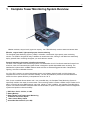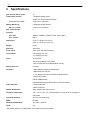
1
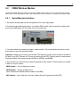
Complete Tower Monitoring System
USER MANUAL
Visit our website at www.dpstelecom.com for the latest PDF manual and FAQs.
April 1, 2013
D-UM-TWRMN-12003
Firmware Version 1.0
Revision History
July 12, 2013
Added battery shelf life specifications
April 1, 2013
Added part numbers for spares/replacement components
January 28, 2013 Initial Release
This document contains proprietary information which is protected by copyright. All rights are reserved. No part of this
document may be photocopied without prior written consent of DPS Telecom.
All software and manuals are copyrighted by DPS Telecom. Said software and manuals may not be reproduced, copied,
transmitted or used to make a derivative work, by either mechanical, electronic or any other means in whole or in part, without
prior written consent from DPS Telecom, except as required by United States copyright laws.
© 2013 DPS Telecom
Notice
The material in this manual is for information purposes and is subject to change without notice. DPS Telecom shall not be
liable for errors contained herein or consequential damages in connection with the furnishing, performance, or use of this
manual.
Contents
Visit our w ebsite at w w w .dpstelecom .com for the latest PDF m anual and FAQs
1 Complete Tower Monitoring System Overview
1
2 Specifications
2
3 Shipping List
3
3.1 Spare and Optional Parts
4 Installation
5
6
4.1 Tools Needed
6
4.2 Battery Installation
7
4.3 How to Connect Power
10
4.4 How to Connect Conduit Fittings
10
4.5 How to Connect Antenna
11
5 NetGuardian 216 G3 Back Panel
12
5.1 LAN Connection
12
5.2 CDMA Wireless Modem
13
5.2.1
Sprint Modem Activation
13
5.2.2
Verizon Modem Activation
16
6 NetGuardian 216 G3 Front Panel
18
6.1 Craft Port
18
6.2 Alarm Speaker
18
6.3 Discrete Alarms
19
7 Quick Start: How to Connect to the Complete Tower Monitoring System
20
7.1 ...via Craft Port (using TTY Interface)
20
7.2 ...via LAN
22
8 TTY Interface
23
8.1 Set DNP3 Parameters
9 Complete Tower Monitoring System Web Browser
9.1 Logging on to the Complete Tower Monitoring System
9.1.1
Changing the Default Password
10 Edit Menu Field Descriptions
24
25
25
26
27
10.1 System
27
10.2 Ethernet
28
10.3 DNP3
29
10.4 Heater Automation
29
10.5 Serial Ports
30
10.6 Notifications
31
10.7 Base Alarms
32
10.8 System Alarms
33
10.9 Controls
34
10.10Analogs
34
10.11Date and Time
35
10.12Timers
36
10.13Reboot
36
11 Monitor Menus
37
11.1 Base Alarms
37
11.2 System Alarms
38
11.3 Controls
38
11.4 Analogs
39
11.5 Heater
39
11.6 Event Log
39
12 Firmware Upgrade
40
13 Front and Back Panel LED
41
14 Reference Section
42
14.1 DNP3 Device Profile
15 Frequently Asked Questions
15.1 General FAQs
42
49
49
16 Technical Support
51
17 End User License Agreement
52
1
1
Complete Tower Monitoring System Overview
Weather resistant, easy-to-install, right-size capacity - the CTMS effectively monitors towers and remote sites.
Effective, easy-to-install, light-capacity tower alarm monitoring
The Complete Tower Monitoring System (CTMS) is a durable, customizable, light-capacity tower monitoring
solution. The CTMS is designed for easy installation at remote tower sites, making it cost-effective to seamlessly
deploy powerful alarm monitoring throughout your entire telecom network.
Powerful monitoring for towers in hostile environments
The brain of the Complete Tower Monitoring System is a NetGuardian 216 G3. Conformal coated and housed in an
aluminum case, this time-tested telco-grade remote is designed to provide dependable tower monitoring. The
NetGuardian is placed within a NEMA stainless steel enclosure to withstand aggressive levels of temperature,
lightning, and other undesirable elements.
An A/C to D/C converter, an external temperature sensor, and a battery backed up with a trickle charger are
integrated into the unit to ensure continuous reliability. The unit also features a processor-controlled heater that
allows the unit to operate efficiently in temperatures as low as -30° C.
With 10 user controlled discrete alarms and 1 user controlled relay, the Complete Tower Monitoring System is
specifically scaled to the needs of remote towers. This monitoring solution includes a CDMA Verizon modem and is
able to communicate using DNP3 protocol over serial, cellular, or LAN. In addition, the Complete Tower Monitoring
System can interface with both LAN-based radio and cellular data, to report to existing DNP3 network management
systems and provide continuous visibility.
DNP3 Over Serial, Cellular, or LAN
Battery Backup
Battery Heater and Temperature Monitoring
10 Discrete User Alarm Inputs
1 User Control Relay Output
Accessible Web Interface (via LAN)
2
2
Specifications
User Discrete Alarm Inputs:
10
Temperature Sensors:
1 Integrated Analog Sensor
Support for 1 External Analog Sensor
Tem perature Thresholds:
Battery Monitoring:
Battery Thresholds:
User Control Relays:
4 (High and Low , Major/Minor)
2 Integrated Analog Sensors
4 (High and Low , Major/Minor)
1
Protocols
Over LAN:
SNMPv1, SNMPv2c, TELNET, HTTP, Email, DNP3
Over Cellular:
DNP3
Dimensions:
20.00" H x 20.00" W x 8.00" D
(50.8 cm x 50.8 cm x 20.32 cm)
Weight:
60 lbs.
Mounting:
Wall mount
Power Input:
110V A/C & 24V Battery Backup
Current Draw:
0.25 Amp @ 110V A/C
2.11 Amp @ 110V A/C
Fuses:
10 Amp Fuse
32V 25 Amp FlatType Fuse Inserts
+24V 3/4 Amp GMT Fuse (NetGuardian 216 G3)
Battery Shelf Life:
9 months*
Interfaces:
1 RJ45 10BaseT half-duplex Ethernet port
1 DB9 front-panel craft port
1 - 1/8 Stereo connector for external temperature probe
1 Push button switch
Cellular CDMA Modem
RS232/RS485 Serial port (Build option instead of Cellular)
Visual Interface:
6 Front Panel LEDs
2 Back Panel LED
Audible Notification:
Alarm speaker with volume control
Industrial Temperature:
-22°–+158° F (-30°–+70° C) when heater is running, which is contingent on
main power
Operating Humidity:
0%–95% non-condensing
MTBF:
60 years
Windows Compatibility:
XP, Vista, 7 32/64 bit
RoHS:
5/6
*The battery needs to be charged within 9 months from manufactured date.
3
3
Shipping List
Please make sure all of the following items are included with your Complete Tower Monitoring System. If parts are
missing, or if you ever need to order new parts, please refer to the part numbers listed and call DPS Telecom at 1800-622-3314.
Base Unit
D-UM-TWRMN-12003
NetGuardian 216 G3
D-PK-NG216-12088.00001
Complete Tower Monitoring System User Manual
D-UM-TWRMN-12003
CTMS Resource CD
900MHz Antenna
2-901-00900-00
3/4-Amp GMT Fuse
3 ft. Antenna Cable
Cable
D-PR-125-10A-03
6 in. External Temperature Sensor
x2
2-741-00500-00
D-PR-998-10A-06
4
6 ft. DB9M-DB9F Download Cable
D-PR-045-10A-04
Antenna Surge Protector
2-908-00090-00
14 ft. Ethernet Cable
D-PR-923-10B-14
5
3.1
Spare and Optional Parts
UPS 24aH Battery
3-904-00001-00
UPS 12aH Battery
3-904-00002-00
Fuse Block, 30A
2-790-60030-00
PLC Relay
3-902-00024-00
12VAC Surge Protector
3-960-00069-00
Compact Fan Heater
3-964-04640-00
External Temp Sensor
D-PR-998-10A-07
UPS 12aH Battery
3-904-00002-00
Fuse, Midget 30A 125V
2-740-03000-00
Freewave Cellular Bridge
3-968-00002-00
Freewave Radio
3-968-00001-00
6
4
4.1
Installation
Tools Needed
To install the NetGuardian, you'll need the following tools:
Phillips No. 2 Screwdriver
PC with terminal emulator,
such as HyperTerminal
Small Standard No. 2 Screwdriver
7
4.2
Battery Installation
Upon receiving your unit, you will find the battery packaged separately. Use the following instruction to install the
battery.
What you will need:
1 Rechargeable Battery Module
1 Battery Back Panel (attached to unit)
8 3/4" Screws
1 Phillips No. 2 Screwdriver
Warning:
Only qualified specialist personnel may install and start up the device. Always ensure protection against electric
shock. Always keep flames, embers, and sparks away from the battery and observe thermal and mechanical
limits.
To install the battery:
1. Open the Complete Tower Monitoring System. Use your screwdriver to remove the battery back panel. The panel
will be inside of the weather-proof casing, attached to the upper right-hand side of the unit. Hold on to your removed
screws as you will need them in the next step. Once you have detached the panel, place it on a surface outside of
the unit.
The Battery panel located inside the CTMS
2. Take the battery and place it on top of the back panel. Using the screws you just removed, attach the battery to
the panel.
8
Screw the battery onto the top of the battery panel
3. Using the remaining screws that were shipped with the unit, attach the battery (now with panel) to the inside of
the unit. Make sure the Battery input is facing downwards, pointed toward the NetGuardian 216G3.
Screw the battery with back panel back into the weather-proof case
4. Connect the wires to the battery. Be sure to insert the wires correctly: positive (red) and negative (black).
Connect the fuses from the NetGuardian 216 G3 into the battery
Warning: Do not proceed to the next step until all of the wires are connected. You can risk serious injury if you connect
the fuses before the wires.
10. Once wires are inserted, open the battery lid and connect the fuses.
9
Open the Battery lid to connect the battery fuses
10
4.3
How to Connect Power
The Complete Tower Monitoring System uses A/C to power its alarms, controls, heater, and to charge its backup
battery. Use the following instructions to connect A/C power to your unit.
To connect the power:
1. Locate the A/C input inside of the weather-proof casing. This will be located at the upper left-hand corner.
2. Attach the three power wires. The left is for 'N' (Neutral), middle is 'GND' (Ground), and right is 'L' (Line).
Insert the three power wires into the A/C power input, located on the upper left-hand side of the unit
4.4
How to Connect Conduit Fittings
The conduit fittings are connected to the weather-proof metal case. There are a total of three conduit fittings. Insert
each conduit fitting to its size-appropriate hole and screw them into place.
The three conduit fittings as seen from the outside of the unit
11
4.5
How to Connect Antenna
The Complete Tower Monitoring System uses an antenna to send DNP3 over wireless with its CDMA modem. Use
the following instructions to connect the antenna.
What you will need:
1 900MHz Antenna
1 3 ft. Antenna Cable
To connect the antenna:
1. Open the weather-proof case of the CTMS and locate the antenna port on the NetGuardian 216 G3 back panel.
2. Attach the antenna cable to the node labeled "Antenna," and tighten the nut to fasten it to the NetGuardian.
3. Now attach the antenna surge protector to the hole in the metal weather-proof case. The surge protector will fit
inside of the smaller hole, located above the three larger conduit holes.
4. Once the surge protector is set up, attach the antenna cable to the protector, tightening the nut to fasten it in
place. Now attach the antenna to the the surge protector on the outside of the case.
12
5
NetGuardian 216 G3 Back Panel
NetGuardian 216 G3 back panel connections
5.1
LAN Connection
To connect the NetGuardian 216 G3 to the LAN, insert a standard RJ45 Ethernet cable into the 10BaseT Ethernet
port on the back of the unit. If the LAN connection is OK, the LNK LED will light SOLID GREEN.
13
5.2
CDMA Wireless Modem
The Complete Tower Monitoring System comes with a CDMA wireless modem. The unit polls devices by sending
DNP3 over a cellular data network. Refer to the following sections for instructions on activating your CDMA modem.
5.2.1
Sprint Modem Activation
1. Set up your wireless data account through Multi-Tech or your Sprint agent.
2. Provide the agent with each modem’s 11-character ESN number, which is printed on a label on the
back of your NetGuardian 216 G3, inside of the unit's metal case.
ESN and model number alternate location
3. You may be asked to provide the modem's model number. This number allows the carrier to verify
this modem as one of it's approved models.
Important: If asked for this number, give the Multi-Tech Systems model number located on the label on
the back of your DPS Telecom unit. You do not need to give the DPS Telecom product or device name.
Examples of Multi-Tech model numbers: MTCBA-xx, MTSMC, and MTMMC.
4. Record the three numbers that your agent will provide for each modem. These numbers are needed
in order to use your modem:
MDN Number – Your 10-digit phone number
MSID Number – Another 10-digit number
(Note: Sometimes the MSID will be the same as the MDN)
MSL Number – Your 6-digit lock code. Also called a Service Programming Code (SPC).
14
5.Access the AT command interface on you DPS Telecom unit by logging into either the serial Craft
port or Telnet interface, then press “M” for the terminal.
TTY Interface
6. Activate your modem by entering the following series of AT commands:
Step
AT Command
Modem Response
Comment
0.
ATE1V1
OK
Echo command and verbose
mode
1.
AT+WSPC=1,xxxxxx<cr>
OK
"xxxxxx" is your programming
code (your MSL). <cr> is
carriage return or Enter key.
2.
AT+WMDN=nnnnnnnnnn<cr> OK
3.
AT+WCMT=1<cr>
"nnnnnnnnnn" is your phone
number (your MDN).
OK
Commits the changes to
memory.
If your MDN and MSID are identical, then you can skip steps 4, 5 and 6.
Wait 10 seconds before issuing the next command. If modem does not respond to AT
commands, power cycle the device.
4.
AT+WSPC=1,xxxxxx<cr>
OK
"xxxxxx" is your programming
code (your MSL).
5.
AT+WIMI=31000ssssssssss
<cr>
OK
"ssssssssss" is your MSID.
6.
AT+WCMT=1<cr>
OK
Commits the changes to
memory.
Wait 10 seconds before issuing the next command. If modem does not respond to AT
commands, power cycle the device.
15
7.
AT+WIOTA=4<cr>
OK
Clears previous IOTA attempts.
8.
AT+WIOTA=1<cr>
+WOAP: "Preparing
Data Services"
OK
Initiates over the air activation.
Note: You must have network
reception for this step. This
process requires about 3
minutes to complete.
Modem Response
When complete, the modem will respond with +WOAR:"Please Retry." This modem response
indicates that you should please retry, but you do not need to do so. Your modem should now be ready
for use.
What to Do If You Do Not Receive the "Please Retry" Response
If you do not receive the "Please Retry" response, turn the power off and then on. Repeat Steps 7 and 8.
Contacting DPS Telecom
If you have any questions or problems, contact Technical Support at DPS Telecom at 559-454-1600.
16
5.2.2
Verizon Modem Activation
WARNING: Do not reset or power off the modem during activation.
1. Set up your wireless data account through Multi-Tech or your Verizon agent.
2. Verify that the antenna is screwed onto the back panel of the unit.
3. Provide the agent with each modem’s 11-character ESN number, which is printed on a label on the
back of your DPS Telecom unit.
ESN and model number alternate location
4. You may be asked to provide the modem's model number. This number allows the carrier to verify
this modem as one of it's approved models.
Important: If asked for this number, give the Multi-Tech Systems model number located on the label on
the back of your DPS Telecom unit. You do not need to give the DPS Telecom product or device name.
Examples of Multi-Tech model numbers: MTCBA-xx, MTSMC, and MTMMC.
5.Access the AT command interface on you DPS Telecom unit by logging into either the serial Craft
port or Telnet interface, then press “M” for the terminal.
TTY Interface
17
6. Activate your modem by entering the following series of AT commands and press <cr> after each
command:
Ste
p
AT Command
Modem Response
Comment
0.
ATE1V1
OK
Echo command and verbose mode
1.
AT+WRMP=2
OK
Allows roaming in order to perform
over-the-air programming
2.
AT+CREG?
+CREG: 0,1
or
+CREG: 0,5 (Roaming)
Note: Activation may not work if the
modem is roaming (+CREG: 0,5).
Note: If modem responds with anything
other than +CREG: 0,1 or +CREG: 0,5
wait 30 seconds and repeat step 2.
3.
ATD*22899;
+WOT1: "Programming in
Process"
+WOT2: "Programming
successful"
OFFLINE
Note: Make sure that CREG command
responded with +CREG: 0,1
or +CREG: 0,5 before starting step 3.
Note: Ensure there is a semi-colon
";"after the dial string entered above, or
the call made will be a circuit-data call.
Note: If you get +WOTS:
"Programming Unsuccessful" repeat
step 3.
Your Modem should now be ready for use.
7. Reset or power cycle the device before continuing with provisioning.
Contacting DPS Telecom
If you have any questions or problems, contact Technical Support at DPS Telecom at 559-454-1600.
18
6
NetGuardian 216 G3 Front Panel
NetGuardian 216 G3 Front panel connections
6.1
Craft Port
Use the front panel craft port to connect the NetGuardian 216 G3 to a PC for onsite unit configuration. To use the
craft port, connect the included DB9 download cable from your PC's COM port to the craft port. Pinout is shown
above for reference, but this is a standard DB9 to DB9.
6.2
Alarm Speaker
The NetGuardian 216 G3 has a built-in speaker for local audible alarm notification. The NetGuardian 216 G3 ships
with the speaker turned off. When enabled, the speaker will beep repeatedly when new alarms happen.
To enable the speaker:
1. Log-in to Web Interface
2. Go to Edit Menu and select Timers
3. Change Sound on time setting to something other than zero.
4. Click Save
To adjust the speaker volume, use the volume control thumb wheel on the NetGuardian's front panel.
19
6.3
Discrete Alarms
Dry Contact
Contact to Ground
NetGuardian case
– Batt.
NetGuardian case
GND
GND
Alarm
Alarm
– Batt.
Note: Make sure that grounds have a common referencethis is usually done by tying grounds together.
5 Discrete alarm points can connect as a dry contact or a contact to ground
The Complete Tower Monitoring System's NetGuardian 216 G3 features 10 user discrete alarm inputs - also called
digital inputs or contact closures. Discrete alarms are either active or inactive, so they're typically used to monitor
on/off conditions like power outages, equipment failures, door alarms and so on.
The NetGuardian's discrete alarm points are single-lead signals referenced to ground. The ground side of each alarm
point is internally wired to ground, so alarm points can connect either as a dry contact or a contact to ground.
In a dry contact alarm: The alarm lead brings a contact to the ground lead, activating the alarm.
In a contact to ground alarm: A single wire brings a contact to an external ground, activating the alarm.
You can reverse the polarity of each individual discrete alarm point, so that the alarm is activated when the contact
is open. This is done with a software configuration change.
20
7
Quick Start: How to Connect to the Complete Tower
Monitoring System
Most NetGuardian users find it easiest to give the unit an IP address, subnet and gateway through the front craft
port (TTY interface) to start. Once these settings are saved and you reboot the unit, you can access it over LAN to
do the rest of your databasing via the Web Browser interface.
Alternative option: You can skip the TTY interface by using a LAN crossover cable directly from your PC to the
NetGuardian 216 G3 and access its Web Browser. See Section 7.2.
7.1
...via Craft Port (using TTY Interface)
1. The simplest way to connect to the NetGuardian 216 G3 is over a physical cable connection between your
PC's COM port and the unit's craft port. Note: You must be connected via craft port or Telnet to use the TTY
interface. Make sure you are using the straight through (1 to 1) Male to Female DB9-DB9 download cable
provided with your NetGuardian 216 G3 to make a craft port connection. We'll be using HyperTerminal to
connect to the unit in the following example - however, most terminal-emulating programs should work.
To access HyperTerminal using Windows:
2. Click on the Start menu > select Programs > Accessories > Communications > HyperTerminal.
3. At the Connection Description screen, enter a name
for this connection. You may also select an icon. The
name and icon do not affect your ability to connect to
the unit.
4. At the Connect To screen, select Com port you'll
be using from the drop down and click OK. (COM1 is
the most commonly used.)
21
5. Select the following COM port options:
• Bits per second: 9600
• Data bits: 8
• Parity: None
• Stop bits: 1
• Flow control: None
Once connected, you will see a blank, white
HyperTerminal screen. Press Enter to activate the
configuration menu.
6. When prompted, enter the default user name
admin and password dpstelecom. NOTE: If you
don't receive a prompt for your user name and
password, check the Com port you are using on your
PC and make sure you are using the cable provided.
7. The NetGuardian 216 G3's main main menu will
appear. Type C for C)onfig, then E for E)thernet.
Configure the unit's IP address, subnet mask, and
default gateway.
8. ESC to the main menu. When asked if you'd like
to save your changes, type Y for Y)es. Reboot the
NetGuardian 216 G3 to save its new configuration.
Additional cables can be ordered from DPS
Telecom: Part number D-PR-045-10A-04
22
Be sure to change the IP of your computer back to one that operates on your network. Now you're ready to do the
rest of your configuration via LAN. Plug your LAN cable into the NetGuardian 216 G3 and see Section 9, "Logging
On to the NetGuardian 216 G3" to continue databasing using the Web Browser.
7.2
...via LAN
Connection through Ethernet port
To connect to the NetGuardian 216 G3 via LAN, all you need is the unit's IP address (Default IP address is
192.168.1.100).
If you DON'T have LAN, but DO have physical access to the NetGuardian 216 G3, connect using a LAN
crossover cable. NOTE: Newer PCs should be able to use a standard straight-through LAN cable and handle the
crossover for you. To do this, you will temporarily change your PC's IP address and subnet mask to match the
NetGuardian's factory default IP settings. Follow these steps:
1.
Get a LAN crossover cable and plug it directly into the NetGuardian 216 G3's LAN port.
2.
Look up your PC's current IP address and subnet mask, and write this information down.
3.
Reset your PC's IP address to 192.168.1.200. Contact your IT department if you are unsure how to do this.
4.
Reset your PC's subnet mask to 255.255.0.0. You may have to reboot your PC to apply your changes.
5.
Once the IP address and subnet mask of your computer coincide with the unit, you can access the
NetGuardian 216 G3 via a Telnet session or via Web browser by using the unit's default IP address of
192.168.1.100.
6.
Provision the NetGuardian 216 G3 with the appropriate information, then change your computer's IP
address and subnet mask back to their original settings.
Now you're ready to do the rest of your configuration via LAN. Plug your LAN cable into the NetGuardian 216 G3
23
and see Section 9, "Logging On to the NetGuardian 216 G3" to continue databasing using the Web Browser.
8
TTY Interface
The TTY interface is the NetGuardian's built-in interface for basic configuration. From the TTY interface, you can:
Edit the IPA, subnet, and gateway
Configure data ports
Set DNP3 Parameters
Ping other devices on the network
Set unit back to factory defaults
Debug and troubleshoot
For more advanced configuration tools, please use the Web Browser Interface.
For Telnet, connect to the IP address at port 2002 to access the configuration menus after initial LAN/WAN setup.
Telnet sessions are established at port 2002, not the standard Telnet port as an added security measure.
If you're using Windows 7, then you'll need to install telnet before you can use the TTY interface. To install telnet,
open up your command line (type "cmd" into the search bar in the Start Menu). Select cmd.exe to run the
command line.
From the command line, type in pkgmgr /iu:"TelnetServer" then press enter. When the command prompt
appears again, the installation is complete.
Menu Shortcut Keys
The letters before or enclosed in parentheses () are menu shortcut keys. Press the shortcut key to access that
option. Pressing the ESC key will always bring you back to the previous level. Entries are not case sensitive.
24
8.1
Set DNP3 Parameters
To set DNP3 Parameters:
1. Login to the TTY Interface.
2. Select C)onfig.
3. Select D)NP3.
From the DNP3 menu, you have the option to configure:
Address
Mode (LAN, Serial, Cellular)
Protocol (TCP or VDP)
LAN Port
25
9
Complete Tower Monitoring System Web Browser
The Complete Tower Monitoring System features a built-in
Web Browser Interface that allows you to manage alarms
and configure the unit through the Internet or your Intranet.
You can quickly set up alarm point descriptions, view alarm
status, issue controls, and configure paging information, and
more using most commonly used browsers.
NOTE: Max # of users allowed to simultaneously access
the CTMS via the Web is 4.
9.1
Logging on to the Complete Tower Monitoring System
For Web Interface functionality, the unit must first be configured with some basic network information. If this step
has not been done, refer to the section "Quick Start: How to Connect to the NetGuardian 216 G3" for instructions on
initial configuration setup.
1.
To connect to the NetGuardian 216 G3 from your Web browser, enter its IP address in the address bar of your
web browser. It may be helpful to bookmark the logon page to avoid entering this each time.
2.
After connecting to the unit's IP address, enter your login information and click OK. NOTE: The factory default
username is "admin" and the password is "dpstelecom".
3.
In the left frame you will see the Monitor menu (blue) and Edit menu (green) The Monitor menu links are used
to view the current status of alarms. The Edit menu is used to change the unit's configuration settings. All the
software configuration will occur in the Edit menu. The following sections provide detailed information regarding
these functions.
1. Enter your password to enter the NetGuardian 216 G3 Web Browser Interface
26
9.1.1
Changing the Default Password
The password can be configured from the Edit > System screen. The minimum password length is four characters;
however, DPS recommends setting the minimum password length to at least five characters.
Use the following steps to change the logon password:
1. From the Edit menu select System.
2. Enter the new user name in the User field.
3. Enter the new password in the Password field.
4. Click the Save button.
2 - Global System Settings section of the Edit > System menu
NOTE: You will see the following popup when making changes to the NetGuardian 216 G3 from the Edit menu. It
will appear when confirming your changes to the database, either by clicking Next in the setup wizards or the Save
button.
3 - Commit to NVRAM popup
27
10 Edit Menu Field Descriptions
10.1
System
From the Edit > System menu, you will configure and edit the global system, T/Mon and control settings for the
NetGuardian 216 G3.
The Edit > System menu
Name
Location
Contact
"From" Email Address
SNMP GET String
SNMP SET String
User
Password
Initialize Configuration
Upgrade Firmware
Global System Settings
A name for this NetGuardian 216 G3. (Optional field)
The location of this NetGuardian 216 G3. (Optional field)
Contact telephone number for the person responsible for this NetGuardian 216 G3.
(Optional field)
A valid email address used by the NetGuardian 216 G3 for sending email alarm
notifications.
Community name for SNMP requests. (case-sensitive).
Community name for SNMP SET requests. (case-sensitive).
Used to change the username for logging into the unit.
Used to change the password for logging into the unit (case-sensitive).
System Controls
Used to restore all factory default settings to the NetGuardian 216 G3. Do not initialize
the non-volatile RAM (NVRAM) unless you want to re-enter all of your configuration
settings again.
Clickable link that takes you to the Firmware Load screen, where you'll browse to the
downloaded firmware update saved on your PC.
28
10.2
Ethernet
The Edit > Ethernet menu allows you to define and configure Ethernet settings.
The Edit > Ethernet menu
Unit MAC
Host Name
Enable DHCP
Unit IP
Subnet Mask
Gateway
DNS Server 1
DNS Server 2
Ethernet Settings
Hardware address of the NetGuardian 216 G3. (Not editable - For reference only.)
Used only for web browsing. Example: If you don't want to remember this NetGuardian's
IP address, you can type in a name is this field, such as NG216G3. Once you save and
reboot the unit, you can now browse to it locally by simply typing in "NG216G3" in the
address bar. (no "http://" needed).
Used to turn on Dynamic Host Connection Protocol. NOT recommended, because the
unit is assigned an IP address from your DHCP server. The IP you've already assigned to
the unit becomes inactive. Using DHCP means the unit will NOT operate in a T/Mon
environment.
IP address of the NetGuardian 216 G3.
A road sign to the NetGuardian 216 G3, telling it whether your packets should stay on
your local network or be forwarded somewhere else on a wide-area network.
An important parameter if you are connected to a wide-area network. It tells the
NetGuardian which machine is the gateway out of your local network. Set to
255.255.255.255 if not using. Contact your network administrator for this info.
Ethernet Settings
Primary IP address of the domain name server. Set to 255.255.255.255 if not using.
Secondary IP address of the domain name server. Set to 255.255.255.255 is not using.
29
10.3
DNP3
10.4
Heater Automation
Enabled
Turn-on Temperature
Turn-off Temperature
Heater Settings
Used to turn on the automated Battery heater.
Specify the Turn-on Temperature in degrees Fahrenheit (14F - 104F or -10C to 40C). The
unit will automatically turn-on the heater once the ambient temperature falls below the
Turn-on Temperature.
Specify the Turn-off Temperature in degrees Fahrenheit (14F - 104F or -10C to 40C). The
unit will automatically turn-off the heater once the ambient temperature rises above the
Turn-on Temperature.
Note: By default, the ambient temperature is measured through the external sensor. If the external sensor fails, an
"External Temp Sensor Failure" alarm will trigger and ambient temperature measurement will automatically switch
to the internal sensor. If both sensors fail, heater automation will be disabled and the "Internal Temp Sensor
Failure" alarm will be set.
30
10.5
Serial Ports
The Edit > Serial Port menu allows you to change settings depending on the port type of your NetGuardian. From
this menu, you can select a mode of operation, tune the 202 modem, and enable reach-through serial port
functionality.
The Edit > Serial Ports menu
Location
A reminder that your primary serial port is located on the back of the NetGuardian 216
G3 chassis.
Port Configuration
Port Type
Select the serial port for your build of the NetGuardian.
Choose from 232, 485...
Baud, Parity, Stop Bits,
Select the appropriate settings from the drop-down menu.
and Flow Control
RTS Head
Only used if your NetGuardian was built with a 202 modem.
The most commonly used value is 30.
RTS Tail
Only used if your NetGuardian was built with a 202 modem.
The most commonly used value is 10.
Flow Control
31
10.6
Notifications
32
10.7
Base Alarms
33
10.8
System Alarms
34
10.9
Controls
10.10 Analogs
35
10.11 Date and Time
The Edit > Date and Time menu
Time Settings
Select the current month, day, and year from the drop-down menus.
Select the current hour, minutes, and time of day fro the drop-down menus.
Automatic Time Adjustment (NTP)
Enable NTP
Check this box to enable Network Time Protocol.
NTP Server Address or Enter the NTP server's IP address or host name, then click Sync.
Host Name
Example: north-america.pool.ntp.org
Time Zone
Select your time zone from the drop-down menu.
Adjust Clock for Daylight Savings Time (DST)
Enable DST
Check this box to have the NetGuardian 216 G3 observe Daylight Savings.
Start Day
Select the month, weekday, and time when Daylight Savings will begin.
End Day
Select the month, weekday, and time when Daylight Savings will end.
Date
Time
36
10.12 Timers
The Edit > Timers menu
10.13 Reboot
Click on the Reboot link from the Edit menu will reboot the NetGuardian 216 G3 after writing all changes to
NVRAM.
The Edit > Reboot confirmation popup
37
11 Monitor Menus
Enter topic text here.
11.1
Base Alarms
38
11.2
System Alarms
11.3
Controls
39
11.4
Analogs
11.5
Heater
11.6
Event Log
40
12 Firmware Upgrade
To access the Firmware Load screen, click on "Upload" at the top of the screen. For more firmware options, click
on the Edit > System menu. At the bottom of this screen, click the firmware links located in the System Controls
section.
The click able link to upgrade firmware from the Edit > System menu
At the Firmware Load screen, simply browse for the firmware update you've downloaded from www.dpstele.com
and click Load.
Browse for downloaded firmware upgrade
41
13 Front and Back Panel LED
Front panel LEDs
LED
Alarm
Status
Flashing Red
Solid Red
Error
Flashing Green
(Optional)
Wireless
Flashing Green
Status
Power
New alarm
Standing alarm acknowledged
No Function: Reserved for future use
(Optional)
Primary
Craft
Description
Flashing Red
Flashing Red
Data transmitted on PRI Serial
Data received on PRI Serial
Data transmitted from modem
Data received by modem
Flashing Green
NG 216 G3 data transmit over craft port
Flashing Red
NG 216 G3 data receive over craft port
Flashing Green
Application is running
Flashing Red
Boot Loader is running
Solid Green
Off
Power supply OK
No voltage or +24V and GND leads reversed
Back Panel LED Descriptions
LED
PWR
Status
Solid Green
Off
Description
Power supply OK
No voltage or +24V and GND leads reversed
42
14 Reference Section
14.1
DNP3 Device Profile
The following table provides a "Device Profile Document" in the standard format defined in the DNP 3.0
Subset Definitions Document. While it is referred to in the DNP 3.0 Subset Definitions as a
"Document," it is in fact a table, and only a component of a total interoperability guide.
DNP V3.0
DEVICE PROFILE DOCUMENT
(Also see the DNP 3.0 Implementation Table in Section 2)
Vendor Name: DPS Telecom Inc.
Device Name: NetGuardian 216 G3 DNP3
Highest DNP Level Supported:
Device Function:
For Requests:
Level 3
Master
For Responses:
Level 3
Slave
Notable objects, functions, and/or qualifiers supported in addition to the Highest DNP Levels Supported
(the complete list is described in the attached table):
The read function code for Object 50 (Time and Date), variation 1, is supported.
Maximum Data Link Frame Size (octets):
Transmitted: 128
Received:
128
Maximum Data Link Re-tries:
None
Fixed (3)
Maximum Application Fragment Size (octets):
Transmitted: 128
Received:
128
Maximum Application Layer Re-tries:
None
Configurable
Requires Data Link Layer Confirmation:
Never
Always
Sometimes
Requires Application Layer Confirmation:
Never
Always
When reporting Event Data (Slave devices only)
When sending multi-fragment responses (Slave devices only)
Sometimes
43
DNP V3.0
DEVICE PROFILE DOCUMENT
(Also see the DNP 3.0 Implementation Table in Section 2)
Timeouts while waiting for:
Fixed at 2s
None
Fixed at 10s
None
Transmission Delay, 0
Data Link Confirmation:
Complete Appl. Fragment:
Application Confirm:
Complete Appl. Response:
Other:
Sends/Executes Control Operations:
Never
Always
Never
Never
Never
Never
Never
Always
Always
Never
Never
WRITE Binary Outputs:
SELECT/OPERATE:
DIRECT OPERATE:
DIRECT OPERATE - NO ACK:
Count > 1:
Pulse On:
Pulse Off:
Latch On:
Latch Off:
Queue:
Clear Queue:
Reports Binary Input Change Events when no
specific variation requested:
Never
Only time-tagged
Only non-time-tagged
Reports time-tagged Binary Input Change Events
when no specific variation requested:
Never
Binary Input Change With Time
Binary Input Change with Relative Time
44
Sends Unsolicited Responses
Never
Only certain objects
Sometimes (attach explanation)
ENABLE/DISABLE UNSOLICITED Function
codes supported
Sends Static Data in Unsolicited Responses:
Never
When Device Restarts
When Status Flags Change
Counters Roll Over at:
Default Counter Object/Variation:
No Counters Reported
Default Object
No Counters Reported
Configurable (attach explanation)
16 Bits
32 Bits
Other Value: ____
Point-by-point list attached
DNP V3.0
DEVICE PROFILE DOCUMENT
(Also see the DNP 3.0 Implementation Table in Section 2)
Sends Multi-Fragment Responses:
No
Yes
Sequential File Transfer Support:
No
No
No
No
No
No
0
Append File Mode:
Custom Status Code Strings:
Permissions Field:
File Events Assigned to Class:
File Events Send Immediately:
Multiple Blocks in a Fragment:
Max Number of Files Open:
DNP V3.0 Implementation Table
The following table identifies which object variations, function codes, and qualifiers the NetGuardian 216
G3 DNP3 supports in both request messages and in response messages. For static (non-changeevent) objects, request send with qualifiers 00, 01, 06, 07, or 08 will be responded with qualifiers 00 or
01.
45
OBJECT
REQUEST
(Library w ill parse)
RESPONSE
(Library w ill respond w ith)
Function Codes Qualifiers Codes
(dec)
(hex)
Function
Codes (dec)
Qualifiers
Codes (hex)
Object
Variation
Num ber Num ber
Description
1
1
Binary Input
10
2
Binary Output Status
12
1
Control Relay Output
Block
5
6
30
3
32-Bit Analog Input
Without Flag
1
(read)
00, 01
(start-stop)
06 (no range, or all)
129 (response)
00, 01 (start-stop)
(read)
00, 01
(start-stop)
06 (no range, or all)
129 (response)
00, 01 (start-stop)
17, 28
(index)
129 (response)
echo of request
00, 01
(start-stop)
06 (no range, or all)
129 (response)
00, 01 (start-stop)
129 (response)
07 (limited qty = 1)
1
1
(direct op)
(dir. op, noack)
(read)
1
50
1
(read)
Time and Date
2
(write)
07
(limited qty = 1)
07
(limited qty = 1)
06
(no range, or all)
60
1
Class 0 Data
1
60
2
Class 1 Data
1
(read)
06
(no range, or all)
60
3
Class 2 Data
1
(read)
06
(no range, or all)
60
4
Class 3 Data
1
(read)
06
(no range, or all)
(read)
46
3
DNP V3.0 Point List
The tables below identify all the default data points provided by the NetGuardian 216 G3 DNP3.
3.1
Binary Input Points
Binary Input Points
Static Variation: Obj 01 Var 01 - Binary Input w/o status
Request function codes supported: 1 (read)
Point Index
Description
Class
0-9
Discrete Alarms
1
10
Surge Protector Tripped
1
11
Low Battery Warning
1
12
Battery Mode
1
13
Battery Charging
1
14
External Temp Sensor Failure
1
15
Internal Temp Sensor Failure
1
16
Default Configuration
1
17
DNP3 Poller Inactive
1
18
MAC Address not set
1
19
IP not set
1
20
LAN hardware error
1
21
SNMP processing error
1
22
SNMP community error
1
23
LAN TX packet drop
1
24
Notification 1 failed
1
25
Notification 2 failed
1
26
Notification 3 failed
1
27
Notification 4 failed
1
28
Notification 5 failed
1
29
Notification 6 failed
1
30
Notification 7 failed
1
31
Notification 8 failed
1
32
NTP failed
1
33
Time Tick
1
47
34
Serial 1 receive queue full
1
35
Dynamic memory full
1
36
Unit reset
1
37
Cellular: Modem Not Responding
1
38
Cellular: No Signal
1
39
Analog 4: Minor Under Threshold
1
40
Analog 4: Minor Over Threshold
1
41
Analog 4: Major Under Threshold
1
42
Analog 4: Major Over Threshold
1
43
Battery A: Minor Under Threshold
1
44
Battery A: Minor Over Threshold
1
45
Battery A: Major Under Threshold
1
46
Battery A: Major Over Threshold
1
47
Battery B: Minor Under Threshold
1
48
Battery B: Minor Over Threshold
1
49
Battery B: Major Under Threshold
1
50
Battery B: Major Over Threshold
1
51
Internal Temperature: Minor Under Threshold
1
52
Internal Temperature: Minor Over Threshold
1
53
Internal Temperature: Major Under Threshold
1
54
Internal Temperature: Major Over Threshold
1
55
External Temperature: Minor Under Threshold
1
56
External Temperature: Minor Over Threshold
1
57
External Temperature: Major Under Threshold
1
58
External Temperature: Major Over Threshold
1
48
3.2
Binary Output Status Points and Control Relay Output Blocks
The following table lists both the Binary Output Status Points (Object 10) and the Control relay Output
Blocks (Object 12).
Binary Output Status Points
Static Variation: Obj 10 Var 02 - Binary Output Status
Control Variation: Obj 12 Var 01 - Control Relay Output Block
Request function codes supported: 3 (select), 4 (operate)
Supported relay output: Latch on, Latch off.
Point ID
Description
Class
0
Base control 1
2
1
Base control 2 (NOTE: Used for internal heater
control)
2
3.3
Analog Inputs
The following table lists Analog Inputs (Object 30). It is important to note that Analog Inputs, Analog
Output Control Blocks, and Analog Output Statuses are transmitted through DNP as singed numbers.
Analog Inputs
Static Variation: Obj 30 Var 03 - 32-Bit analog w/o flag
Request function codes supported: 1 (read)
Point ID
Description
Default Unit
Class
0
Base analog 1
Voltage (VDC)
3
1
Base analog 2
Voltage (VDC)
3
2
Base analog 3
Voltage (VDC)
3
3
Base analog 4
Voltage (VDC)
3
4
Battery Monitor A
Voltage (VDC)
3
5
Battery Monitor B
Voltage (VDC)
3
6
Internal Temperature
Temperature (F)
3
7
External Temperature (NOTE:
Temperature (F)
used to monitor internal heater)
3
49
15 Frequently Asked Questions
Here are answers to some common questions from NetGuardian 216 G3 users. The latest FAQs can
be found on the NetGuardian 216 G3 support web page, http://www.dpstele.com.
If you have a question about the NetGuardian 216 G3, please call us at (559) 454-1600 or e-mail us at
[email protected]
15.1
General FAQs
Q. How do I telnet to the NetGuardian 216 G3?
A. You must use Port 2002 to connect to the NetGuardian 216 G3. Configure your Telnet client to
connect using TCP/IP (not "Telnet," or any other port options). For connection information, enter the
IP address of the NetGuardian 216 G3 and Port 2002. For example, to connect to the NetGuardian
216 G3 using the standard Windows Telnet client, click Start, click Run, and type "telnet
<NetGuardian 216 G3 IP address> 2002."
Q. How do I connect my NetGuardian 216 G3 to the LAN?
A. To connect your NetGuardian 216 G3 to your LAN, you need to configure the unit IP address, the
subnet mask and the default gateway. A sample configuration could look like this:
Unit Address: 192.168.1.100
subnet mask: 255.255.255.0
Default Gateway: 192.168.1.1
Save your changes by writing to NVRAM and reboot. Any change to the unit's IP configuration
requires a reboot.
Q. When I connect to the NetGuardian 216 G3 through the craft port on the front panel it either
doesn't work right or it doesn't work at all. What's going on?
A. Make sure your using the right COM port settings. Your COM port settings should read:
Bits per second: 9600 (9600 baud)
Data bits: 8
Parity: None
Stop bits: 1
Flow control: None
Important! Flow control must be set to none. Flow control normally defaults to hardware in most
terminal programs, and this will not work correctly with the NetGuardian 216 G3.
Q. What characteristics of an alarm point can be configured through software? For instance,
can point 4 be used to sense an active-low signal, or point 5 to sense a level or an edge?
A. The unit's standard configuration is for all alarm points to be level-sensed. You cannot use
configuration software to convert alarm points to TTL (edge-sensed) operation. TTL alarm points
are a hardware option that must be specified when you order your NetGuardian 216 G3. Ordering
TTL points for your NetGuardian 216 G3 does not add to the cost of the unit What you can do with
the configuration software is change any alarm point from "Normal" to "Reversed" operation.
Switching to Reversed operation has different effects, depending on the kind of input connected to
the alarm point:
· If the alarm input generates an active-high signal, switching to Reversed operation means
the NetGuardian 216 G3 will declare an alarm in the absence of the active-high signal, creating the
practical equivalent of an active-low alarm.
If the alarm input generates an active-low signal, switching to Reversed operation means the
50
NetGuardian 216 G3 will declare an alarm in the absence of the active-low signal, creating the
practical equivalent of an active-high alarm.
If the alarm input is normally open, switching to Reversed operation converts it to a normally
closed alarm point.
If the alarm input is normally closed, switching to Reversed operation converts it to a normally
open alarm point.
51
16 Technical Support
DPS Telecom products are backed by our courteous, friendly Technical Support representatives, who
will give you the best in fast and accurate customer service. To help us help you better, please take the
following steps before calling Technical Support:
1. Check the DPS Telecom website.
You will find answers to many common questions on the DPS Telecom website, at http://www.
dpstele.com/support/. Look here first for a fast solution to your problem.
2. Prepare relevant information.
Having important information about your DPS Telecom product in hand when you call will greatly
reduce the time it takes to answer your questions. If you do not have all of the information when you
call, our Technical Support representatives can assist you in gathering it. Please write the information
down for easy access. Please have your user manual and hardware serial number ready.
3. Have access to troubled equipment.
Please be at or near your equipment when you call DPS Telecom Technical Support. This will help us
solve your problem more efficiently.
4. Call during Customer Support hours.
Customer support hours are Monday through Friday, from 7 A.M. to 6 P.M., Pacific time. The DPS
Telecom Technical Support phone number is (559) 454-1600.
Emergency Assistance: Emergency assistance is available 24 hours a day, 7 days a week. For
emergency assistance after hours, allow the phone to ring until it is answered with a paging message.
You will be asked to enter your phone number. An on-call technical support representative will return
your call as soon as possible.
52
17 End User License Agreement
All Software and firmware used in, for, or in connection with the Product, parts, subsystems, or derivatives thereof,
in whatever form, including, without limitation, source code, object code and microcode, including any computer
programs and any documentation relating to or describing such Software is furnished to the End User only under a
non-exclusive perpetual license solely for End User's use with the Product.
The Software may not be copied or modified, in whole or in part, for any purpose whatsoever. The Software may not
be reverse engineered, compiled, or disassembled. No title to or ownership of the Software or any of its parts is
transferred to the End User. Title to all patents, copyrights, trade secrets, and any other applicable rights shall
remain with the DPS Telecom.
DPS Telecom's warranty and limitation on its liability for the Software is as described in the warranty information
provided to End User in the Product Manual.
End User shall indemnify DPS Telecom and hold it harmless for and against any and all claims, damages, losses,
costs, expenses, obligations, liabilities, fees and costs and all amounts paid in settlement of any claim, action or
suit which may be asserted against DPS Telecom which arise out of or are related to the non-fulfillment of any
covenant or obligation of End User in connection with this Agreement.
This Agreement shall be construed and enforced in accordance with the laws of the State of California, without
regard to choice of law principles and excluding the provisions of the UN Convention on Contracts for the
International Sale of Goods. Any dispute arising out of the Agreement shall be commenced and maintained only in
Fresno County, California. In the event suit is brought or an attorney is retained by any party to this Agreement to
seek interpretation or construction of any term or provision of this Agreement, to enforce the terms of this
Agreement, to collect any money due, or to obtain any money damages or equitable relief for breach, the prevailing
party shall be entitled to recover, in addition to any other available remedy, reimbursement for reasonable attorneys'
fees, court costs, costs of investigation, and other related expenses.
53
Notes
Warranty
DPS Telecom warrants, to the original purchaser only, that its products a) substantially conform to DPS' published
specifications and b) are substantially free from defects in material and workmanship. This warranty expires two years from the
date of product delivery with respect to hardware and ninety days from the date of product delivery with respect to software.
If the purchaser discovers within these periods a failure of the product to substantially conform to the specifications or that
the product is not substantially free from defects in material and workmanship, the purchaser must promply notify DPS. Within
reasonable time after notification, DPS will endeavor to correct any substantial non-conformance with the specifications or
substantial defects in material and workmanship, with new or used replacement parts. All warranty service will be performed at
the company's office in Fresno, California, at no charge to the purchaser, other than the cost of shipping to and from DPS,
which shall be the responsiblity of the purchaser. If DPS is unable to repair the product to conform to the warranty, DPS will
provide at its option one of the following: a replacement product or a refund of the purchase price for the non-conforming
product. These remedies are the purchaser's only remedies for breach of warranty. Prior to initial use the purchaser shall have
determined the suitability of the product for its intended use. DPS does not warrant a) any product, components or parts not
manufactured by DPS, b) defects caused by the purchaser's failure to provide a suitable installation environment for the
product, c) damage caused by use of the product for purposes other than those for which it was designed, d) damage caused
by disasters such as fire, flood, wind or lightning unless and to the extent that the product specification provides for
resistance to a defined disaster, e) damage caused by unauthorized attachments or modifications, f) damage during shipment
from the purchaser to DPS, or g) any abuse or misuse by the purchaser.
THE FOREGOING WARRANTIES ARE IN LIEU OF ALL OTHER WARRANTIES, EXPRESS OR IMPLIED, INCLUDING BUT
NOT LIMITED TO THE IMPLIED WARRANTIES OF MERCHANTABILITY AND FITNESS FOR A PARTICULAR
PURPOSE.
In no event will DPS be liable for any special, incidental, or consequential damages based on breach of warranty, breach of
contract, negligence, strict tort, or any other legal theory. Damages that DPS will not be responsible for include but are not
limited to, loss of profits; loss of savings or revenue; loss of use of the product or any associated equipment; cost of capital;
cost of any substitute equipment, facilities or services; downtime; claims of third parties including customers; and injury to
property.
The purchaser shall fill out the requested information on the Product Warranty Card and mail the card to DPS. This card
provides information that helps DPS make product improvements and develop new products.
For an additional fee DPS may, at its option, make available by written agreement only an extended warranty providing an
additional period of time for the applicability of the standard warranty.
Technical Support
If a purchaser believes that a product is not operating in substantial conformance with DPS' published specifications or there
appear to be defects in material and workmanship, the purchaser should contact our technical support representatives. If the
problem cannot be corrected over the telephone and the product and problem are covered by the warranty, the technical
support representative will authorize the return of the product for service and provide shipping information. If the product is
out of warranty, repair charges will be quoted. All non-warranty repairs receive a 90-day warranty.
Free Tech Support is Only a Click Away
Need help with your alarm monitoring? DPS Information Services are ready to
serve you … in your email or over the Web!
www.DpsTelecom.com
Free Tech Support in Your Email: The Protocol Alarm Monitoring Ezine
The Protocol Alarm Monitoring Ezine is your free email
tech support alert, delivered directly to your in-box
every two weeks. Every issue has news you can use
right away:
•
Expert tips on using your alarm monitoring
equipment - advanced techniques that will save
you hours of work
•
Educational White Papers deliver fast informal
tutorials on SNMP, ASCII processing, TL1 and
other alarm monitoring technologies
•
New product and upgrade announcements keep
you up to date with the latest technology
•
Exclusive access to special offers for DPS
Telecom Factory Training, product upgrade offers
and discounts
To get your free subscription to
The Protocol register online at
www.TheProtocol.com/register
Free Tech Support on the Web: MyDPS
MyDPS is your personalized, members-only online resource.
Registering for MyDPS is fast, free, and gives you exclusive
access to:
•
•
•
•
Firmware and software downloads and upgrades
Product manuals
Product datasheets
Exclusive user forms
Register for MyDPS online at
www.DpsTelecom.com/register
(800) 622-3314 • www.DpsTelecom.com • 4955 E. Yale Avenue, Fresno, California 93727