1
Centermount
Extending
Articulating
(CMX) Legrest
Installation, Set-Up & Adjustment
User Manual
TRD0272- CMX Legrest Set-Up/ Adjustment Manual, Rev 2.1- February 5, 2010
-2-
-3-
i
Impor tant!
The most important link in the delivery chain is the
end user. The user must be satisfied with the product
in terms of function, safety and aesthetics. No sale is
complete unless the end user receives thorough training
in all aspects of the care and use of the system. A
complete instruction session with your customer is
essential.
Only the dealer and the health care professional can
ensure that the system is set up properly and safely
for the specific needs of the individual user.
Training
Installation and set-up of the Centermount Extending/ Articulatiing (CMX) Legrest must only be
performed by a trained technician or healthcare professional. If you are not certified as an
installer, please arrange immediately for training by a Motion Concepts Technician or Sales
Representative. Every effort will be made to meet your training needs.
Note: Before proceeding with the installation/ set-up, please ensure that no pages are missing
from this manual.
Tools
The following tools are required for the installation/ set-up of the CMX Legrest:
Wrenches: 7/16”, 1/2”
Socket wrenches: 7/16”, 1/2”
Allen keys: 3/16”, 1/4”, 1/8”
Screw Drivers
TRD0272- CMX Legrest Set-Up/ Adjustment Manual, Rev 2.1- February 5, 2010
-4-
1 . 0 - A s s e m b l y O ve r v i e w D r a w i n g s
Assemb l y Over vie w Dr a wing
-5-
1 . 0 - A s s e m b l y O ve r v i e w D r a w i n g s
Assemb l y Over vie w Dr a wing
TRD0272- CMX Legrest Set-Up/ Adjustment Manual, Rev 2.1- February 5, 2010
-6-
2 . 0 - C M X L e g r e s t D e s i g n O ve r v i e w
CMX Le g r est Design Over vie w
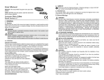
The CMX Centermount Legrest Assembly is installed onto the seat frame (not shown) of the upper seating
system via the legrest receivers. The CMX Legrest has been designed with 3 optional pre-tilt positions. By
altering the mounting holes used in the upper legrest mount (tube), the pre-tilt angle can be adjusted -see
Figure 1.0 below. The CMX Legrest may be configured with either a centermount footplate (per Figure 1.0),
or individual (split) footplates (Figure 2.0), and is available in three different knee-to-heel sizes (13”-17”,
15”-19” or 17”-21”).
The centermount foot platform option offers dynamic plantarflexion and provides up to a maximum 6.75”
of extension. The split footplates provide the same range of extension, with independent angle adjustment
and the footplates may be installed either at the same height (uni-level), or they may be offset from each
other (bi-level installation). *Please Note: dynamic plantarflexion is not available with the split footplate option.
The following sections will provide greater detail on CMX Legrest installation, assembly and set-up.
Figure 1.0
CMX Legrest w/ Center mount Foot Pla tf or m
A.
A. Pre-Tilt Angle (+7°)
B. Pre-Tilt Angle (90°)
B.
C. Pre-Tilt Angle (-7°)
C.
upper legest
mount
Retracted Position
(three (3) pre-tilt options available)
Extended Position*
5”
approx. 6.7
n
o
si
n
e
xt
e
of
(*note: The angle at extension depends on initial pre-tilt angle)
-7-
2 . 0 - C M X L e g r e s t D e s i g n O ve r v i e w
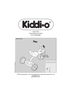
Figure 2.0
CMX Legrest w/
Split Footpla te Assemb l y
Retracted Position
o
(90 set-up shown)
Extended Position
approx. 6.75” of extension
Split Footpla te Ass’y
(w/ Bi-Level / Offset Footplates)
TRD0272- CMX Legrest Set-Up/ Adjustment Manual, Rev 2.1- February 5, 2010
-8-
3.0 - CMX Le g rest Set-Up and Adjustment
CMX Le g r est Set-Up/ Adjustment
A) Legrest Depth Adjustment: Depth adjustment for the CMX Legrest assembly is controlled via
the mounting position of the legrest receivers (left & right). The legrest receivers (x2) are installed into the
upper seat frame (not shown) and can be adjusted in and out to achieve the desired depth.
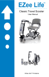
B) Knee-to-Heel Adjustments: KTH adjustments are controlled via the legrest extension tube. The
extension tube is available in to different sizes (13”-17” KTH and 15”-19” KTH) in order to achieve the
desired knee-to-heel length. Heights are determined by the mounting location of the upper link, and by the
mounting location of the footplate mounting bracket on the lower extension tube. (all extension tube
adjustments are provided in 1/2” increments). Refer to Figure 3.0 and Figure 4.0.
Important! When setting the Knee-to-Heel (KTH) height, ensure the final set-up provides sufficient
ground clearance when the CMX legrest is in the down/ fully retracted position. A minimum of 3”
ground clearance is recommended.
i
Figure 3.0
Knee-to-Heel
Adjustments
Sea t De pth
Adjustment
Available in 3 sizes:
13-17” knee-to-heel
15-19” knee-to-heel
17-21” knee-to-heel
The entire CMX Legrest
Assembly can be adjusted to
the desired seat depth inside
the seat frame via the legrest
receivers (not shown).
Maximum
KTH height
Extension Tube
Upper Adjustment*
(1/2” increments)
Lower Adjustment
(1/2” increments)
maintain a minimum
3” ground clearance
calf pad not shown
Footplate
Interface
Bracket
*refer to Figure 4.0
-9-
3.0 - CMX Le g rest Set-Up and Adjustment
C) Upper Extension Tube Installation/ Adjustment: The upper extension tube may be adjusted
in 1/2” increments to achieve the desired knee-to-heel height (the maximum KTH height and range is
determined by the size of extension tube selected). To inst all: The desired mounting hole in the upper
extension tube is aligned with the slots in the main tube and secured to the upper links (left & right) of the
CMX legrest assembly. (Refer to illustrations in Figure 4.0 below).
Figure 4.0
Upper Extension Tube Installa tion
cam plate
main tube
upper link (left)
main
tube
upper link
(left)
Cam Plate (Cover) not shown
TRD0272- CMX Legrest Set-Up/ Adjustment Manual, Rev 2.1- February 5, 2010
- 10 -
3.0 - CMX Le g rest Set-Up and Adjustment
D) Lower Extension Tube Adjustment:
Centermount Platform & Split Footplate Installation
The lower extension tube is utilized in combination with the upper extension tube to set or adjust the final
knee-to-heel height. Adjustments are available in 1/2” increments. The final KTH height is dictated by the
mounting location of the centermount foot plaform or split footplates.
Inst allation:
Determine the desired mounting hole on the lower extension tube and align it with the footplate mounting
bracket(s). Secure the mounting bracket(s) using the hardware provided*. Refer to Figure 5A, 5B and 5C
that follow, for an illustration of the various footplate installations available for the CMX Legrest).
*Note: Mounting hardware will vary depending on the type and configuration of the footplate(s) being installed.
i Important Reminder! Prior to footplate installation, ensure there is sufficient clearance between
the ground and the extension tube when the CMX legrest is in the down/ fully retracted position. A
minimum 3” of ground clearance is recommended.
Figure 5A
Center mount Foot
Pla tf or m Installa tion
1/2”
Figure 5B
Split Footpla te (Uni-Level) Installa tion
Both footplates (interface brackets) are installed onto the
extension tube using a single set of mounting hardware.
- 11 -
3.0 - CMX Le g rest Set-Up and Adjustment
Figure 5C
Split Footpla te (Bi-Level) Installa tion
Each footplate is installed using it’s own set of hardware
in different hole locations on the extension tube.
{ }
1/2” increments
NOTE: Once installed, the initial footplate angle and plantarflex angle (centermount platform only) can
then be adjusted. Please refer to Sections E and F, (p.12-13) for detailed instructions.
TRD0272- CMX Legrest Set-Up/ Adjustment Manual, Rev 2.1- February 5, 2010
- 12 -
3.0 - CMX Le g rest Set-Up and Adjustment
E) CENTERMOUNT PLATFORM- Initial Angle Adjustment & Dynamic Plantarflexion:
The CMX with centermount foot platform is designed to allow adjustment for the initial foot platform angle
(when placed in the down/ fully retracted position). The initial centermount platform angle is adjusted via
the Plantarflex Plate (refer to Figure 6.0 below). Dynamic plantarflexion* refers to the ability of the footplatform to gradually angle downward as the legrest is extended. (See Figure 7.0).
i Important!
*Dynamic Plantarflex is not available with the Split Footplate option on the CMX Legrest
Figure 6.0
I n i t i a l F o o t p l a t e A n g l e S e t - u p (Centermount Platform)
The Plantarflex Plate is raised or lowered (via
3 screws) to make contact with the footplate
interface bracket and set the initial footplate
angle. (note
note: must be set-up with the legrest
in the down (fully retracted) position
{
Plantarflex
Plate
Initial Foot
Platform Angle
raising the plantarflex plate will
lower the initial footplate angle
footplate interface
bracket
lowering the plantarflex plate will
raise the initial footplate angle
- 13 -
3.0 - CMX Le g rest Set-Up and Adjustment
Figure 7.0
Dynamic Plantarflexion
(for Centermount Platform Only)
As the CMX legrest elevates/extends, the plantarflex
angle automatically increases (i.e.; the foot platform falls
forward) to relieve strain on the hamstings and improve
overall comfort when the legrest is fully extended.
F) SPLIT FOOTPLATES- Angle Adjustment:
The CMX Legrest with Split Footplates (Bi-Level or Uni-Level) can be independently adjusted to set
the desired footplate angle for each footplate. Once set, these angles will remain consistent throughout the extension and retraction of the legrest assembly. (The Split Footplate design does not allow
for plantarflex angle adjustment).
The footplate angles are adjusted via a screw at the rear of each footplate interface bracket. (Refer to
Figure 8.0 below).
Split footplates may be angle adjusted
independently from each other.
increase
decrease
Angle
Adjustment
Figure 8.0
footplate angle +/- 10
(approx.)
ο
TRD0272- CMX Legrest Set-Up/ Adjustment Manual, Rev 2.1- February 5, 2010
- 14 -
3.0 - CMX Le g rest Set-Up and Adjustment
G) Calf Pad Installation/ Adjustment: The calf pads are installed by securing the pad mounting
brackets onto the Cam Plate of the CMX legrest assembly. The calf pads may be independently adjusted (as
required) to ensure a proper level of comfort for the end user, specifically in the extended legrest position.
The calf pad is adjustable laterally and/or vertically by aligning the slots in the mounting bracket with the
threaded holes in the calf pad. The calf pads may also be angle adjusted by installing one of the pad
mounting screws into the horizontal slot at the bottom of the mounting bracket. Please refer to Figure 9.0,
as well as the sample calf pad configuration diagrams below.
Figure 9.0
Cam Plate
Horizontal
Adjustment
Vertical
Adjustment
(offset)
Calf Pad
Angle Adjustment slot
FRONT VIEW
REAR VIEW (left calf pad)
Calf Pad Adjustment (Sample Configurations)
Standard Position
Extended Position
(maximum)
Raised Offset
Lowered Offset
Angled
- 15 -
N OT E S :
TRD0272- CMX Legrest Set-Up/ Adjustment Manual, Rev 2.1- February 5, 2010
USA
700 Ensminger Rd. Suite 112
Tonawanda, NY, USA 14150
716-447-0050
888-433-6818
Canada
84 Citation Dr. Units 1-3
Concord, Ontario,
Canada L4K 1C9
905-695-0134
www.motionconcepts.com