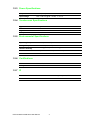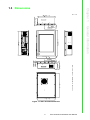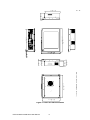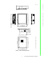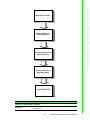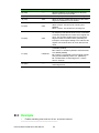
1
User Manual IPPC-6152A/6172A/ 6192A 15” XGA /17” SXGA / 19” SXGA TFT LCD (LED Backlight) Core™ i7/i5/i3 Haswell Platform Industrial Panel PC with 2 x PCI Slots Copyright The documentation and the software included with this product are copyrighted 2014 by Advantech Co., Ltd. All rights are reserved. Advantech Co., Ltd. reserves the right to make improvements in the products described in this manual at any time without notice. No part of this manual may be reproduced, copied, translated or transmitted in any form or by any means without the prior written permission of Advantech Co., Ltd. Information provided in this manual is intended to be accurate and reliable. However, Advantech Co., Ltd. assumes no responsibility for its use, nor for any infringements of the rights of third parties, which may result from its use. Acknowledgements Intel and Pentium are trademarks of Intel Corporation. Microsoft Windows® are registered trademarks of Microsoft Corp. All other product names or trademarks are properties of their respective owners. Product Warranty (2 years) Advantech warrants to you, the original purchaser, that each of its products will be free from defects in materials and workmanship for two years from the date of purchase. This warranty does not apply to any products which have been repaired or altered by persons other than repair personnel authorized by Advantech, or which have been subject to misuse, abuse, accident or improper installation. Advantech assumes no liability under the terms of this warranty as a consequence of such events. Because of Advantech’s high quality-control standards and rigorous testing, most of our customers never need to use our repair service. If an Advantech product is defective, it will be repaired or replaced at no charge during the warranty period. For outof-warranty repairs, you will be billed according to the cost of replacement materials, service time and freight. Please consult your dealer for more details. If you think you have a defective product, follow these steps: 1. Collect all the information about the problem encountered. (For example, CPU speed, Advantech products used, other hardware and software used, etc.) Note anything abnormal and list any onscreen messages you get when the problem occurs. 2. Call your dealer and describe the problem. Please have your manual, product, and any helpful information readily available. 3. If your product is diagnosed as defective, obtain an RMA (return merchandize authorization) number from your dealer. This allows us to process your return more quickly. 4. Carefully pack the defective product, a fully-completed Repair and Replacement Order Card and a photocopy proof of purchase date (such as your sales receipt) in a shippable container. A product returned without proof of the purchase date is not eligible for warranty service. 5. Write the RMA number visibly on the outside of the package and ship it prepaid to your dealer. Part No. 2003615250 Edition 1 Printed in China January 2014 IPPC-6152A/6172A/6192A User Manual ii Declaration of Conformity CE This product has passed the CE test for environmental specifications. Test conditions for passing included the equipment being operated within an industrial enclosure. In order to protect the product from being damaged by ESD (Electrostatic Discharge) and EMI leakage, we strongly recommend the use of CE-compliant industrial enclosure products. FCC Class A Note: This equipment has been tested and found to comply with the limits for a Class A digital device, pursuant to part 15 of the FCC Rules. These limits are designed to provide reasonable protection against harmful interference when the equipment is operated in a commercial environment. This equipment generates, uses, and can radiate radio frequency energy and, if not installed and used in accordance with the instruction manual, may cause harmful interference to radio communications. Operation of this equipment in a residential area is likely to cause harmful interference in which case the user will be required to correct the interference at his own expense. Technical Support and Assistance 1. 2. Visit the Advantech web site at www.advantech.com/support where you can find the latest information about the product. Contact your distributor, sales representative, or Advantech's customer service center for technical support if you need additional assistance. Please have the following information ready before you call: – Product name and serial number – Description of your peripheral attachments – Description of your software (operating system, version, application software, etc.) – A complete description of the problem – The exact wording of any error messages iii IPPC-6152A/6172A/6192A User Manual Safety Instructions 1. 2. 3. 4. 5. 6. 7. 8. 9. 10. 11. 12. 13. 14. 15. Read these safety instructions carefully. Keep this User Manual for later reference. Disconnect this equipment from any AC outlet before cleaning. Use a damp cloth. Do not use liquid or spray detergents for cleaning. For plug-in equipment, the power outlet socket must be located near the equipment and must be easily accessible. Keep this equipment away from humidity. Put this equipment on a reliable surface during installation. Dropping it or letting it fall may cause damage. The openings on the enclosure are for air convection. Protect the equipment from overheating. DO NOT COVER THE OPENINGS. Make sure the voltage of the power source is correct before connecting the equipment to the power outlet. Position the power cord so that people cannot step on it. Do not place anything over the power cord. All cautions and warnings on the equipment should be noted. If the equipment is not used for a long time, disconnect it from the power source to avoid damage by transient overvoltage. Never pour any liquid into an opening. This may cause fire or electrical shock. Never open the equipment. For safety reasons, the equipment should be opened only by qualified service personnel. If one of the following situations arises, get the equipment checked by service personnel: a. The power cord or plug is damaged. b. Liquid has penetrated into the equipment. c. The equipment has been exposed to moisture. d. The equipment does not work well, or you cannot get it to work according to the user's manual. e. The equipment has been dropped and damaged. f. The equipment has obvious signs of breakage. DO NOT LEAVE THIS EQUIPMENT IN AN ENVIRONMENT WHERE THE STORAGE TEMPERATURE MAY GO BELOW -40° C OR ABOVE 85° C. THIS COULD DAMAGE THE EQUIPMENT. THE EQUIPMENT SHOULD BE IN A CONTROLLED ENVIRONMENT. IPPC-6152A/6172A/6192A User Manual iv Safety Precaution - Static Electricity Follow these simple precautions to protect yourself from harm and the products from damage. To avoid electrical shock, always disconnect the power from your PC chassis before you work on it. Don't touch any components on the CPU card or other cards while the PC is on. Disconnect power before making any configuration changes. The sudden rush of power as you connect a jumper or install a card may damage sensitive electronic components. Battery Information Batteries, battery packs and accumulators should not be disposed of as unsorted household waste. Please use the public collection system to return, recycle, or treat them in compliance with the local regulations. Warning! There is a danger of explosion if battery is incorrectly replaced. Replace only with same or equivalent type recommended by the manufacturer. Discard used batteries according to the manufacturer's instructions. v IPPC-6152A/6172A/6192A User Manual IPPC-6152A/6172A/6192A User Manual vi Content Chapter 1 General Information ............................1 1.1 1.2 1.4 Introduction ............................................................................................... 2 Specifications ............................................................................................ 3 1.2.1 General ......................................................................................... 3 1.2.2 Standard PC Functions................................................................. 3 1.2.3 Power Specifications..................................................................... 4 1.2.4 Touchscreen Specifications .......................................................... 4 1.2.5 Environmental Specifications........................................................ 4 1.2.6 Certifications ................................................................................. 4 1.2.7 IP................................................................................................... 4 Dimensions ............................................................................................... 5 Figure 1.1 IPPC-6152A Dimensions............................................ 5 Figure 1.2 IPPC-6172A Dimensions............................................ 6 Figure 1.3 IPPC-6192A Dimensions............................................ 7 I/O Function Description............................................................................ 8 2 System Setup .......................................9 2.1 General ................................................................................................... 10 2.1.1 PS/2 Mouse & Keyboard............................................................. 10 2.1.2 VGA Port..................................................................................... 10 2.1.3 Serial COM Ports ........................................................................ 10 2.1.4 USB Ports ................................................................................... 11 2.1.5 Audio Port ................................................................................... 11 2.1.6 Ethernet ...................................................................................... 11 2.1.7 DP Port ....................................................................................... 11 2.1.8 DVI Port ...................................................................................... 11 2.1.9 GPIO Port ................................................................................... 11 2.1.10 PCI Ports..................................................................................... 11 Installing Memory .................................................................................... 12 Installing CPU ......................................................................................... 13 Installing HDD ......................................................................................... 16 Installing DVD ROM (Optional) ............................................................... 18 Installing CFast Riser Card (Optional) .................................................... 21 Mounting Instructions .............................................................................. 21 2.7.1 Panel Mounting ........................................................................... 21 2.7.2 Rack Mounting ............................................................................ 21 1.3 Chapter 2.2 2.3 2.4 2.5 2.6 2.7 Chapter Chapter 3 Jumper Settings & Connectors ........23 3.1 Jumper Settings ...................................................................................... 24 3.1.1 Jumpers & Switches ................................................................... 24 3.1.2 COM4 Settings............................................................................ 25 Table 3.1: COM4 Settings ......................................................... 25 3.1.3 Clear CMOS (JCMOS1).............................................................. 26 4 Intel Chipset .......................................27 4.1 4.2 4.3 Overview ................................................................................................. 28 Utilities and Drivers ................................................................................. 28 Dual/Triple Display Setting...................................................................... 28 vii IPPC-6152A/6172A/6192A User Manual Chapter 5 AMI BIOS Setup................................. 31 5.1 Introduction ............................................................................................. 32 5.1.1 Legend Box................................................................................. 32 5.1.2 List Box ....................................................................................... 32 5.1.3 Sub-menu ................................................................................... 32 BIOS Configuration ................................................................................. 33 5.2.1 Main Setup.................................................................................. 33 5.2.2 Advanced BIOS Setup................................................................ 33 5.2.3 Chipset Setup ............................................................................. 48 5.2.4 Boot Setting Configuration.......................................................... 52 5.2.5 Security Setup ............................................................................ 53 5.2.6 Exit Menu.................................................................................... 53 5.2 Appendix A I/O & Connector Pin Assignments .. 55 A.1 GPIO ....................................................................................................... 56 Appendix B Watchdog Timer Programming ....... 57 B.1 B.2 Overview ................................................................................................. 58 Watchdog Timer Programming ............................................................... 58 Table B.1: Watchdog Timer Registers....................................... 60 Example .................................................................................................. 61 B.3 IPPC-6152A/6172A/6192A User Manual viii Chapter 1 1 General Information 1.1 Introduction The IPPC-6152A/6172A/6192A is an Industrial Panel PC with front USB access, supports the powerful Intel i7/i5/i3 Haswell 4th generation processor, high speed DDR3 memory (up to 32 GB) and two expansion PCI slots. The processor and chipset combination form the foundation of Intel AMT 9.0 vPro management support system, offering remote out-of-band manageability, improved security, and energy efficient performance. Two SATA 2.0 & 3.0 hard driver interface with RAID 0,1 support provides data security. The flat-sealed front panel design also allows easier cleaning and liquid run off. Also, we provide versatile functional options, including CFast, PCI/PCIe and DVD-ROM, to suit customers’ needs. Sturdy Structure The whole system is protected by a firm solid structure. The front panel is made of sturdy aluminum and has strengthened glass. It is shock resistant, and complies with IP65. High Performance The IPPC-6152A/6172A/6192A supports Intel 1150P socket. It supports i7/i5/i3 Haswell 4th generation processor up to 3.1 GHz. Friendly HMI Systems in the IPPC-6152A/6172A/6192A series are equipped with a 15", 17", 19" LCD screen (LED backlight), which provides high resolution display quality. The result is vivid, bright, and sharp quality images. The panel PC is perfectly suited for Windows OS. The touchscreen version enables simple operation, making the Panel PC a solid industrial digital controller interface. In addition friendly HMI design of the IPPC-6152A/6172A/6192A series offers front USB access port and reset key for various requirements. IPPC-6152A/6172A/6192A User Manual 2 1.2.1 General Model IPPC-6152A LCD 15”LCD Specification IPPC-6172A IPPC-6192A 17”LCD 19”LCD Max. Resolution 1024 x 768 1280 x 1024 1280 x 1024 Max. Colors 16.2 M/262 K 16.7 M RGB 6-bit + Hi-FRC data 16.7 M RGB 6-bit + Hi-FRC data Viewing Angle 160/140 170/160 170/160 Luminance 400 cd/m2 350 cd/m2 350 cd/m2 Contrast Ratio 700 1000 1000 Backlight Life 50,000 hrs 50,000 hrs 50,000 hrs Weight 13Kg (28.6lbs) 15 Kg (33.04 lb) 16.6 Kg (35.6 lbs) Dimensions 449.92 x 315.63 x 126.4 mm 481.93 x 355.87 x 132.5 mm 481.93 x 384.6 x 135.5 mm (17.71”x 12.43”x 4.98”) (18.97”x 14.01”x 5.22”) (18.97”x 15.14”x 5.33”) 1.2.2 Standard PC Functions CPU Supports Intel® Core™ i7/i5/i3 processor (up to 3.1 GHz) Chipset Intel Q87 BIOS AMI 64 MB Flash BIOS Memory 4 x DIMM slots, up to 32 G DDR3 (1600 MHz/1333 MHz) Storage 1 Supports 2 x 2.5"SATA 2.0/3.0 HDDs (with Intel RAID 0.1 function) Storage 2 Supports CFast (optional) Supports 8X slim DVD +/- RW (optional) Network 2 x Giga Ethernet ports, 10/100/1000 Mbps GbE LAN1: Intel I217-LM, GbE LAN2: Intel I211 I/O Interface 1 x GPIO 2 x Reserved ports (expansion COMs) 5 x USB Host (1 x front USB 2.0, 4 x USB 3.0) 1 x VGA 1 x DVI port 1 x DP 1 x Line out, 1 x Mic in 1 x Keyboard, 1 x Mouse Expansion Slots 2 x PCI (standard) 2 x PCIe x 1 (optional) System Windows 7/Windows 8 3 IPPC-6152A/6172A/6192A User Manual General Information Display Type 15”TFT LCD (LED backlight) 17”TFT LCD (LED backlight) 19”TFT LCD (LED backlight) Chapter 1 1.2 Specifications 1.2.3 Power Specifications Output Power 350 W (Max.) Input Voltage 100 ~ 240 VAC @ 60 ~ 50 Hz, 7 ~ 3.5 A 1.2.4 Touchscreen Specifications Type Analog resistive 5-wire Resolution 2048 x 2048 Light Transmission 81%+/-3% Lifespan 36,000,000 times 1.2.5 Environmental Specifications Operating Temperature 0 ~ 50°C (32 ~ 122°F) Storage Temperature -20 ~ 60°C (-4 ~ 140°F) Relative Humidity 5 ~ 85% @ 40°C (non-condensing) Shock 10 G peak acceleration (11 ms duration) Vibration 5 ~ 500 Hz 1 G RMS 1.2.6 Certifications EMC BSMI, CE, FCC Class A Safety CB, CCC, BSMI, UL 1.2.7 IP Chassis Flat-sealed aluminum die-casting front panel, SGCC enclosure Front Bezel IP IP65 IPPC-6152A/6172A/6192A User Manual 4 8QLWPP General Information 3DQHO&XW'LPHQVLRQ[PP[ Figure 1.1 IPPC-6152A Dimensions 5 Chapter 1 1.3 Dimensions IPPC-6152A/6172A/6192A User Manual Figure 1.2 IPPC-6172A Dimensions 3DEHO&XW'LPHQVLRQV[PP[ 6 IPPC-6152A/6172A/6192A User Manual 8LWPP 3DQHO&XW'LPHQVLRQ454x338mm(17.87"x13.31") IPPC-6152A/6172A/6192A User Manual 7 General Information Figure 1.3 IPPC-6192A Dimensions Chapter 1 8QLWPP 1.4 I/O Function Description A E G J L F H I K M N B C D O P A.Power Switch I.DVI B.Mouse C.Keyboard J.LANx2 K.USB3.0x4 D.AC IN L. Line out E.COM1/2/4 (RS-232) COM3 (RS-232 /RS-422/RS-485) M. Mic N.DVD ROM F.DP O.CFast P.USB2.0 G.GPIO H.VGA IPPC-6152A/6172A/6192A User Manual 8 Chapter 2 System Setup 2 2.1 General Before you start the computer, please follow these procedures for set up: 1. Check and adjust jumpers on the motherboard (see Chapter 3). 2. Install DDR3 SDRAM. 3. Install a CPU. 4. Install add-on cards. 5. Connect the wires, cables and accessories. 6. Mount the computer. 7. Program the BIOS settings. 8. Install an operating system.. Warning! 1. 2. Switch off and unplug every time you access its interior. The motherboard inside the system is composed of many delicate ICs, chips and other integrated circuit components. These components are easily damaged by static shock. When you begin to install components, please: - Avoid touching the metal parts of the motherboard. - Use anti-static ring when handling CPU or SDRAM module. - Put SDRAM modules and the CPU inside an anti-static bag or a similar place before installation. 2.1.1 PS/2 Mouse & Keyboard If you wish to use a full-size desktop keyboard and PS/2 mouse with your panel PC, follow these instructions: 1. Be sure the panel PC is turned off. 2. Attach the keyboard adapter to the 5-pin purple port on the bottom side of the rear cover. 3. Attach the mouse adapter to the 5-pin green port on the bottom side of the rear cover. 2.1.2 VGA Port An external VGA-compatible device may be connected to the system via 15-pin external port on the rear of the unit. The panel PC simultaneously supports an external monitor in addition to its own LCD display. 2.1.3 Serial COM Ports You can easily attach a serial device to the panel PC, such as an external modem or mouse. Follow these instructions: 1. Make sure the panel PC and any other peripheral devices you may have connected to the panel PC are turned off. 2. Attach the interface cable of the serial device to the panel PC's serial port. If necessary, attach the other end of the interface cable to your serial device. Fasten any retaining screws. 3. Turn on any other peripheral devices you may have connected to the panel PC, and then turn on the panel PC. 4. Refer to the manual(s) which accompanied your serial device(s) for instructions on configuring your operating environment to recognize the device(s). 5. Run the BIOS setup program to set the I/O address and IRQ, and configure the jumper settings to change the mode of the COM ports (refer to section 3.1.2). IPPC-6152A/6172A/6192A User Manual 10 An external USB device may be connected to the system via the USB ports located on the rear side of the system unit. 1. Connect the external device to the system. 2. The USB ports support hot plug-in connection. You should install the device driver before you use the device. Chapter 2 2.1.4 USB Ports 2.1.5 Audio Port 2.1.6 Ethernet To install Ethernet for your system: 1. Connect the Ethernet cable. 2. Turn on the panel PC. 3. Run the Ethernet driver to connect up to the network. 2.1.7 DP Port To connect DP monitor. 2.1.8 DVI Port To connect DVI monitor. 2.1.9 GPIO Port Reserved for user configuration. See Appendix A.1 for details. 2.1.10 PCI Ports The device provides 2 PCI ports for users. External PCI card dimension is required not to exceed 167.65 mm (6.6”) x 96.4 mm (3.8”) x 18.7 mm (0.736”). 11 IPPC-6152A/6172A/6192A User Manual System Setup Audio port consists of two plug holes: Mic in and line out. Their functions are as below: Mic in: Record sound via external microphones. Line out: Output sound signal to external devices (e.g speaker, headset, etc). When connected to external audio devices, internal speaker won’t be disabled. 1. Connect audio devices to the system. 2. Install the device drivers before using audio devices. 2.2 Installing Memory 1. 2. Loosen the 6 screws on the back cover and open it. Push outward the lever of the memory slot. 3. Insert the memory and then push back the lever. IPPC-6152A/6172A/6192A User Manual 12 Remove CPU fan. 2. Push the CPU lever outward. System Setup 1. Chapter 2 2.3 Installing CPU 13 IPPC-6152A/6172A/6192A User Manual 3. Remove CPU pin cap. 4. Install CPU. Please note the direction of notched corner of the CPU. IPPC-6152A/6172A/6192A User Manual 14 6. Install CPU fan, and insert the CPU fan cable. System Setup Push back the CPU lever, and then paste the thermal grease (within the accessory box) onto CPU. Chapter 2 5. 15 IPPC-6152A/6172A/6192A User Manual 2.4 Installing HDD 1. Loosen the four screws on the HDD holder. IPPC-6152A/6172A/6192A User Manual 16 Insert the HDD, and fasten the screws (with the accessory box). Chapter 2 2. System Setup 17 IPPC-6152A/6172A/6192A User Manual 3. Fasten the screws. Note! If installing two HDDs, please insert them simultaneously, and then fasten the screws. HDD thickness is required not to exceed 9.5 mm. If above, you can only insert one HDD or SSD. 2.5 Installing DVD ROM (Optional) Install DVD ROM (DVD ROM needs to be purchased by customers themselves): Take out DVD ROM holder and the screws from the accessory box, and put DVD ROM onto the holder. IPPC-6152A/6172A/6192A User Manual 18 Chapter 2 Fix with screws on both sides of the holder. System Setup Install the assembled DVD ROM in the machine. First remove the DVD ROM plate in the machine. 19 IPPC-6152A/6172A/6192A User Manual Install the DVD ROM, and fix with screws. Plug the power data line into the DVD ROM, connect it to 4PIN power via power adapter (within the accessory box), and connect the other end of the data line to SATA1 port of the mainboard. IPPC-6152A/6172A/6192A User Manual 20 Take out the screws from the accessory box and install the CFast riser card, see below. (CFast module part No. IPPC-6152-CFASTE) Chapter 2 2.6 Installing CFast Riser Card (Optional) System Setup Plug in the power cable (within the CFast module), and connect the other end of the cable to Power 4PIN. Plug in the data line, connect the other end to the SATA4 port of the mainboard. 2.7 Mounting Instructions There are two ways to mount the system: panel mounting or rack mounting. 2.7.1 Panel Mounting 1. 2. 3. Take the four mounting brackets out of the accessory box. Attach the four mounting brackets by inserting the screws into the keyhole slots on the cover of the monitor. Use the screws to secure the brackets to the cover. Tighten the screws to secure the monitor to the back panel. 2.7.2 Rack Mounting Please order IPPC-6152A-RMKE, IPPC-6172A-RMKE, or IPPC-6192A-RMKE option kit to install to 19” industrial rack. For the detailed installation process, please refer to IPPC-6152-6172-6192_Series_Mount_Installation_Guide(EN&CH) installation guide accompanied by the machine. 21 IPPC-6152A/6172A/6192A User Manual IPPC-6152A/6172A/6192A User Manual 22 Chapter 3 3 Jumper Settings & Connectors 3.1 Jumper Settings This section tells how to set the jumpers to configure your card. For the locations of each jumper, see the board layout diagram depicted earlier in this chapter. You configure your card to match the needs of your application by setting jumpers. A jumper is the simplest kind of electric switch. It consists of two metal pins and a small metal cap (often protected by a plastic cover) that slides over the pins to connect them. To “close” a jumper you connect the pins with the cap. To “open” a jumper you remove the cap. Sometimes a jumper will have three pins, labeled 1, 2 and 3. In this case you connect either pins 1 and 2 or 2 and 3. Open Closed Closed 2-3 The jumper settings are schematically depicted in this manual as follows: Open Closed Closed 2-3 A pair of needle-nose pliers may be helpful when working with jumpers. If you have any doubts about the best hardware configuration for your application, contact your local distributor or sales representative before you make any changes. Generally, you simply need a standard cable to make most connections. 3.1.1 Jumpers & Switches The motherboard of the IPPC-6152A/6172A/6192A has a number of jumpers that allow you to configure your system to suit your applications. The table below lists the function of each of the board’s jumpers. IPPC-6152A/6172A/6192A User Manual 24 This jumper is used to select RS232 (default)/RS422/RS485. Table 3.1: COM4 Settings RS-232 RS-422 RS-485 Chapter 3 3.1.2 COM4 Settings Jumper Settings & Connectors Pin Pin Name 1 UART_SIN 2 RXD485 3 UART_SIN 4 RXD422 5 UART_SIN 6 RXD232 7 DCD# 8 SOUT 9 COM3_DCD# 10 COM3_SOUT 11 COM3_TXD485N 12 COM3_RXD485P 13 SIN 14 DTR# 15 COM3_SIN 16 COM3_DTR# 17 COM3_TXD485P 18 COM3_RXD485N 25 IPPC-6152A/6172A/6192A User Manual 3.1.3 Clear CMOS (JCMOS1) This jumper is used to erase CMOS data and reset system BIOS information. Follow the procedures below to clear the CMOS. 1. Turn off the system. 2. Remove the Jumper JCMOS1(1-2). 3. Close jumper JCMOS1(2-3). 4. Remove the Jumper JCMOS1(2-3). 5. Close jumper JCMOS1(1-2). 6. Turn on the system.The CMOS is now cleared. 7. Set the BIOS to default. JCMOS1 Clear RTC/CMOS Description Reset the register bit in RTC (short 2-3) Normal operation (short 1-2) Pin Pin Name 1 NC 2 RTCRST# 3 GND IPPC-6152A/6172A/6192A User Manual 26 Chapter 4 Intel Chipset 4 4.1 Overview In IPPC-6152A/6172A/6192A, Advantech provides a CD-ROM with utilities and drivers included. 4.2 Utilities and Drivers Intel Chipset Software Installation Utility Path: \INF\ Available for the OS's below: Microsoft Windows 7 Microsoft Windows 8 4.3 Dual/Triple Display Setting 1. Click the icon. IPPC-6152A/6172A/6192A User Manual 28 3. Click “Display”. Intel Chipset Select “Graphics Properties”. Chapter 4 2. 29 IPPC-6152A/6172A/6192A User Manual 4. Click the down arrow of Display. 5. Select “Multiple Displays” and configure the parameter. IPPC-6152A/6172A/6192A User Manual 30 Chapter 5 AMI BIOS Setup 5 5.1 Introduction The main BIOS setup menu is the first screen that you can navigate. Each main BIOS setup menu option is described in this user's guide. The Main BIOS setup menu screen has two main frames. The left frame displays all the options that can be configured. "Grayed-out" options cannot be configured. Options is blue can be. The right frame displays the key legend. Above the key legend is an area reserved for a text message. When an option is selected in the left frame, it is highlighted in white. Often a text message will accompany it. 5.1.1 Legend Box The BIOS setup/utility uses a key-based navigation system called hot keys. Most of the BIOS setup utility hot keys can be used at any time during the setup navigation process. Keys Function Description , Left/Right The Left and Right <Arrow> keys allow you to select an setup screen. For example: Main screen, Advanced screen, Chipset screen, and so on. , Up/Down The Up and Down <Arrow> keys allow you to select an setup item or sub-screen. +, - Plus/Minus The Plus and Minus <Arrow> keys allow you to change the field value of a particular setup item. For example: Date and Time. F1 The <F1> key allows you to display the General Help screen. Press the <F1> key to open the General Help screen. F2 Reset previous settings F3 Reset BIOS factory defaults F4 The <F10> key allows you to save any changes you have made and exit Setup. Press the <F4> key to save your changes. ESC The <Esc> key allows you to discard any changes you have made and exit the Setup. Press the <Esc> key to exit the setup without saving your changes. Enter The <Enter> key allows you to display or change the setup option listed for a particular setup item. The <Enter> key can also allow you to display the setup sub- screens. 5.1.2 List Box This box appears only in the opening screen. The box displays an initial list of configurable items in the menu you selected. 5.1.3 Sub-menu Note that a right pointer symbol (u) appears to the left of certain fields. This pointer indicates that you can display a sub-menu from this field. A sub-menu contains additional options for a field parameter. To display a sub-menu, move the highlight to the field and press <Enter>. The sub-menu appears. Use the legend keys to enter values and move from field to field within a sub-menu as you would within a menu. Use the <Esc> key to return to the main menu. Take some time to familiarize yourself with the legend keys and their corresponding functions. Practice navigating through the various menus and submenus. While moving around through the Setup program, note that explanations appear in the Item Specific Help window located to the right of each menu. This window displays the help text for the currently highlighted field. IPPC-6152A/6172A/6192A User Manual 32 5.2.1 Main Setup When you first enter the Setup Utility, you will enter the Main setup screen. You can always return to the Main setup screen by selecting the Main tab. There are two Main Setup options. They are described in this section. The Main BIOS Setup screen is shown below. Chapter 5 5.2 BIOS Configuration AMI BIOS Setup System Time/System Date Use this option to change the system time and date. Highlight System Time or System Date using the <Arrow> keys. Enter new values through the keyboard. Press the <Tab> key or the <Arrow> keys to move between fields. The date must be entered in MM/DD/YY format. The time is entered in HH:MM:SS format. 5.2.2 Advanced BIOS Setup Select the Advanced tab from the setup screen to enter the Advanced BIOS Setup screen. You can select any of the items in the left frame of the screen, such as SuperIO Configuration, to go to the sub menu for that item. You can display an Advanced BIOS Setup option by highlighting it using the <Arrow> keys. All Advanced BIOS Setup options are described in this section. The Advanced BIOS Setup screen is shown below. The sub menus are described on the following pages. 33 IPPC-6152A/6172A/6192A User Manual 5.2.2.1 ACPI Settings Enable ACPI Auto Configuration The default configuration is [Disabled]. Enable Hibernation The default configuration is [Enabled]. ACPI Sleep State The default configuration is [S3 only]. Users can select other options. Lock Legacy Resources The default configuration is [Disabled]. S3 Video Repost The default configuration is [Disabled]. IPPC-6152A/6172A/6192A User Manual 34 35 IPPC-6152A/6172A/6192A User Manual AMI BIOS Setup 5.2.2.3 CPU Configuration This option provides CPU parameters for reference. Users can configure to their favorite settings. Chapter 5 5.2.2.2 S5 RTC Wake Settings Wake system with Fixed Time The default configuration is [Disabled]. IPPC-6152A/6172A/6192A User Manual 36 37 IPPC-6152A/6172A/6192A User Manual AMI BIOS Setup Users can select HDD mode in this option: IDE, AHCI, RAID. Chapter 5 5.2.2.4 SATA Configuration Users can check SATA enabled devices in this page. 5.2.2.5 Intel(R) Rapid Start Technology The default configuration of Intel(R) Rapid Start Technology option is [Disabled]. 5.2.2.6 PCH-FW Configuration Users can view ME version information in this page. The default configuration of MDES BIOS Status Code is [Disabled]. “Me FW Image Re-Flash” inside “Firmware Update Configuration” is set as [Disabled] by default. IPPC-6152A/6172A/6192A User Manual 38 AMI BIOS Setup 5.2.2.8 Intel AMT [Enabled] Chapter 5 5.2.2.7 Intel (R) Anti-Theft Technology Configuration The default configuration of Intel (R) Anti-Theft Technology is [Enabled]. The default configuration is of Enter Intel (R) AT Suspend Mode is [Disabled]. Intel AMT [Enabled] Intel AMT is configured as [Enabled] by default. Intel Active Management Technology (AMT) is based on hardware, which supports remote management and out-band security. BIOS Hotkey Pressed [Disabled] BIOS key is disabled by default. 39 IPPC-6152A/6172A/6192A User Manual MEBx Selection Screen [Disabled] Intel Management Engine BIOS Extension (MEBx). MEBx is used to select screen function. The default configuration is disabled. Hide Un-Configure ME Confirmation [Disabled] Hide unlimited ME function confirmation. The default configuration is disabled. MEBx Debug Message Output [Disabled] Output MEBx debug message. The default configuration is disabled. Un-Configure ME [Disabled] ME function configuration. The default configuration is disabled. AMT Wait Time The wait time to enter AMT is set as 0. Disable ME [Disabled] The default configuration is disabled. Users can enable it if necessary. ASF [Enabled] The default configuration of ASF is enabled. Activate Remote Assistance Process [Disabled] Remote assistance function is disabled by default. USB Configure [Enabled] USB configuration function is enabled by default. PET Progress [Enabled] PET function expansion is enabled by default. AMT CIRA Timeout The value is set as 0 by default, and cannot be modified. Watch Dog [Disabled] Watchdog function is disabled by default, users can enable it if necessary. OS Timer and BIOS Timer are only effective when watchdog function is enabled! 5.2.2.9 USB Configuration Legacy USB Support [Enabled] USB support is enabled by default. Users can select to enable or disable it. XHCI Hand-off [Enabled] XHCI Hand-off is enabled by default. IPPC-6152A/6172A/6192A User Manual 40 5.2.2.10 Super IO Configuration Serial Port 1 Configuration COM1 port configuration. Users can configure COM1 address according to their requirements, the default configuration is AUTO. 41 IPPC-6152A/6172A/6192A User Manual AMI BIOS Setup EHCI Hand-off [Disabled] EHCI (EnhancedHost Controller Interface) is disabled by default. USB Mass Storage Driver Support [Enabled] This function is enabled by default. USB Transfer time-out [20sec] USB transfer timeout value is set as 20 seconds by default. The options are 1 sec, 5 sec, 10 sec, 20 sec. Device reset time-out [20sec] Device reset timeout value is set as 20 seconds by default. The options are 10 sec, 20 sec, 30 sec, 40 sec. Device power-up delay [auto] Device powerup delay is set as auto by default. Users can select auto or manual. Chapter 5 Serial Port 2 Configuration COM2 port configuration. Users can configure COM2 address according to their requirements, the default configuration is AUTO. The default configuration of Device Mode is [Standard Serial Port Mode]. Users can also set as [IrDA 1.0(HP SIR) Mode] or ASKIR Mode. IPPC-6152A/6172A/6192A User Manual 42 Smart Fan Function The default configuration is enabled. Smart Fan Mode Configuration This item is used to configure CPU fan and system fan mode. Users can configure according to their requirements. 43 AMI BIOS Setup Digital I/O Configuration Digital I/O Pin is set as Input by default. Users can set as Output High or Output Low according to their requirements. Chapter 5 IPPC-6152A/6172A/6192A User Manual Case Open Warning The default configuration is disabled. Users can enable it if necessary. Wake On Ring The default configuration is disabled. Users can enable it if necessary. Deep S4/S5 The default configuration is disabled. Users can enable it if necessary. Watch Dog Timer The default configuration is disabled. Users can enable it if necessary. 5.2.2.11 H/W Monitor System temperature This option shows the current system temperature of the entire machine. CPU temperature (PECI) This option shows the current CPU temperature. CPU FAN Speed This option shows the current CPU fan speed detected. SYSTEM1 FAN Speed No system fan installed in FAN1, so no speed displayed. SYSTEM2 FAN Speed IPPC-6152A/6172A/6192A User Manual 44 5.2.2.12 Second Super IO Configuration Serial Port 3 Configuration - Serial Port [Enabled] The default configuration of COM3 is enabled. - Change Settings [Auto] Users can configure COM3 address according to their requirements. The default configuration is AUTO. 45 IPPC-6152A/6172A/6192A User Manual AMI BIOS Setup Chapter 5 This option shows the current system fan speed detected. SYSTEM3 FAN Speed This option shows the currents system fan speed detected. SYSTEM4FAN Speed No system fan installed in FAN4, so no speed displayed. CPU Warning Temperature [Disabled] CPU warning temperature. The default configuration is disabled. Users can configure according to their requirements. ACPI Shutdown Temperature [Disabled] ACPI shutdown temperature. The default configuration is disabled. Users can configure according to their requirements. - RS485 AUTO Flow [Disabled] RS485 flow control is disabled by default. Users can configure according to their requirements. Serial Port 4 Configuration - Serial Port [Enabled] COM3 is enabled by default. - ChangeSettings [Auto] Users can configure COM4 address according to their requirements.The default configuration is AUTO. 5.2.2.13 Serial Port Console Redirection ConsoleRedirection [Disabled] The default configuration is disabled. Users can enable it according to their requirements. IPPC-6152A/6172A/6192A User Manual 46 Chapter 5 5.2.3 Chipset Setup 5.2.3.1 PCH-IO Configuration AMI BIOS Setup USB Configuration 47 IPPC-6152A/6172A/6192A User Manual - USB Precondition [Disabled] The default configuration is disabled. Users can enable it according to their requirements. - XHCI Mode [Auto] The default configuration is disabled. Users can enable it according to their requirements. - BTCG [Enabled] The default configuration is enabled. PCH Azalia Configuration Azalia [Auto] is set as auto detection by default. Users can enable or disable it according to their requirements. - LAN1 Controller [Enabled] The default configuration of LAN1 port is enabled. - LAN1 PXE OpROM [Disabled] LAN1 PXE OpROM function is disabled by default. - Wake On LAN [Disabled] Wake On LAN function is disabled by default. - LAN2 Controller [Enabled] The default configuration of LAN2 port is enabled. - LAN2 PXE OpROM [Disabled] LAN2 PXE OpROM function is disabled by default. - PCIE Wake [Disabled] PCIE Wake function is disabled by default. Users can enable it according to their requirements. - RestoreAC Power LOSS [Power Off] The default configuration is disabled. Power on when alternating current turns down, and the device will not restart. Users can configure it as Power On or Last State according to their requirements. IPPC-6152A/6172A/6192A User Manual 48 AMI BIOS Setup Chapter 5 5.2.3.2 System Agent (SA) Configuration Graphics Configuration 49 IPPC-6152A/6172A/6192A User Manual - Primary IGFX Boot Display [LVDS/eDP] Users can select DVI, CRT or DP according to their requirements. - Secondary IGFX Boot Display [CRT] The secondary boot item is CRT. Users can select LVDS/eDP, DVI, DP or OFF according to their requirements. - LVDS Panel Type LVDS panel’s resolution. 1024x768 for IPPC-6152, and 1280 x 1024 for IPPC-6172 and IPPC-6192. NB PCIe Configuration - PEG0-Gen X[GEN1] The default configuration is GEN1. Users can modify it to GEN2 if necessary. - Run-time C7 Allowed [Enabled] The default configuration is enabled. - Enable PEG [Enabled] The default configuration is enabled. - Detect Non-Compliance Device [Disabled] The default configuration is disabled. - Program PCIe ASPM after OpROM [Disabled] IPPC-6152A/6172A/6192A User Manual 50 Setup Prompt Timeout [1] The default setting is 1 second. Users can configure it according to their requirements. The value is higher, the time for staying on the initial boot screen is longer. Bootup NumLock State [On] Keyboard NumLock indicators are ON by default when booting up. Users can modify it if necessary. Quiet Boot [Disabled] The default configuration is disabled. Boot Option #1/Boot Option #2 It shows different hardware options. Hard Drive BBS Priorities Give priority to hard drive boot. 51 IPPC-6152A/6172A/6192A User Manual AMI BIOS Setup 5.2.4 Boot Setting Configuration Chapter 5 The default configuration is disabled. - PEG0 De-emphasis Control-3.5 dB The default configuration is-3.5dB. Users can modify it to -6dB if necessary. - PEG0 -ASPM [Auto] The default configuration is Auto. Users can modify it to ASPM L0s, ASPM L1, ASPML0Sl1 if necessary. - PEG Sampler Calibrate [Disabled] The default configuration is Disabled. Users can modify it to AUTO or Enabled if necessary. - Swing Control [Full] The default configuration is Full. Users can modify it to Half if necessary. - PEG RxCEM LoopBack Mode [Disabled] The default configuration is Disabled. 5.2.5 Security Setup Administrator Password Set administrator password. User Password Set user password. 5.2.6 Exit Menu Save Changes and Exit Save changes and exit the screen. Press OK or Cancel. Discard Changes and Exit Discard changes and exit the screen. Press OK or Cancel. Restore Default Restore default BIOS configuration. Save as User Defaults Save user default configuration. Restore User Defaults Restore user default configuration. IPPC-6152A/6172A/6192A User Manual 52 Appendix A A I/O & Connector Pin Assignments A.1 GPIO Pin Pin Name 1 GPIO0 from GP70 of SIO 2 GPIO1 from GP71 of SIO 3 GPIO2 from GP72 of SIO 4 GPIO3 from GP73 of SIO 5 GPIO4 from GP74 of SIO 6 GPIO5 from GP75 of SIO 7 GPIO6 from GP76 of SIO 8 GPIO7 from GP77 of SIO 9 GND IPPC-6152A/6172A/6192A User Manual 56 Appendix B Watchdog Timer Programming B B.1 Overview The IPPC-6152A/IPPC-6172A/IPPC-6192A cards' watchdog timer can be used to monitor system software operation and take corrective action if the software fails to function after the programmed period. The watchdog timer is built into the I/O controller NCT6776D. It provides the following functions for user programming: 1. Can be enabled and disabled by user's program. 2. Timer can be set from 1 to 255 seconds. 3. Generates an interrupt or resets signal if the software fails to reset the timer after time-out. B.2 Watchdog Timer Programming The I/O port address of the watchdog timer is 2E(hex), and data port address is 2F(hex). IPPC-6152A/6172A/6192A User Manual 58 Select register of watchdog timer Enable the function of watchdog timer Use the function of watchdog timer Lock NCT6776D Table B.1: Watchdog Timer Registers Address of Register (2E) Attribute Read/Write Value (2F) & Description 59 IPPC-6152A/6172A/6192A User Manual Appendix B Watchdog Timer Programming Unlock NCT6776D Table B.1: Watchdog Timer Registers 87 (hex) ----- Write this address to I/O address port 2E (hex) twice to unlock the NCT6776D. 07 (hex) write Write 08 (hex) to select register of watchdog timer. 30 (hex) write Write 01 (hex) to enable the function of the watchdog timer. Disabled is set as default. write Set seconds or minutes as units for the timer. Write 0 to bit 3: set second as counting unit. [default] Write 1 to bit 3: set minutes as counting unit. write 0: stop timer [default] 01~FF (hex): The amount of the count, in seconds or minutes, depends on the value set in register F5 (hex). This number decides how long the watchdog timer waits for strobe before generating an interrupt or reset signal. Writing a new value to this register can reset the timer to count with the new value. F7 (hex) read/write Bit 7:Write 1 to enable mouse to reset the timer, 0 to disable. [default] Bit 6: Write 1 to enable keyboard to reset the timer, 0 to disable.[default] Bit 5: Write 1 to generate a timeout signal immediately and automatically return to 0. [default=0] Bit 4: Read status of watchdog timer, 1 means timer is “timeout”. AA (hex) ----- Write this address to I/O port 2E (hex) to lock the watchdog timer 2. F5 (hex) F6 (hex) B.3 Example 1. Enable watchdog timer and set 10 sec. as timeout interval. ;----------------------------------------------------------IPPC-6152A/6172A/6192A User Manual 60 61 IPPC-6152A/6172A/6192A User Manual Appendix B Watchdog Timer Programming Mov dx,2eh ; Unlock NCT6776D Mov al,87h Out dx,al Out dx,al ;----------------------------------------------------------Mov al,07h ; Select registers of watchdog timer Out dx,al Inc dx Mov al,08h Out dx,al ;----------------------------------------------------------Dec dx ; Enable the function of watchdog timer Mov al,30h Out dx,al Inc dx Mov al,01h Out dx,al ;----------------------------------------------------------Dec dx ; Set second as counting unit Mov al,0f5h Out dx,al Inc dx In al,dx And al,not 08h Out dx,al ;----------------------------------------------------------Dec dx ; Set timeout interval as 10 seconds and start counting Mov al,0f6h Out dx,al Inc dx Mov al,10 Out dx,al ;----------------------------------------------------------Dec dx ; Lock NCT6776D Mov al,0aah Out dx,al 2. Enable watchdog timer and set 5 minutes as timeout interval. ;----------------------------------------------------------Mov dx,2eh ; Unlock NCT6776D Mov al,87h Out dx,al Out dx,al ;----------------------------------------------------------Mov al,07h ; Select registers of watchdog timer Out dx,al Inc dx Mov al,08h Out dx,al ;----------------------------------------------------------Dec dx ; Enable the function of watchdog timer Mov al,30h Out dx,al Inc dx Mov al,01h Out dx,al ;----------------------------------------------------------Dec dx ; Set minute as counting unit Mov al,0f5h Out dx,al Inc dx In al,dx Or al,08h Out dx,al ;----------------------------------------------------------Dec dx ; Set timeout interval as 5 minutes and start counting Mov al,0f6h Out dx,al Inc dx Mov al,5 Out dx,al ;----------------------------------------------------------Dec dx ; Lock NCT6776D Mov al,0aah Out dx,al 3. Enable watchdog timer to be reset by mouse ;----------------------------------------------------------Mov dx,2eh ; Unlock NCT6776D Mov al,87h Out dx,al Out dx,al ;----------------------------------------------------------Mov al,07h ; Select registers of watchdog timer Out dx,al Inc dx Mov al,08h Out dx,al ;----------------------------------------------------------Dec dx ; Enable the function of watchdog timer Mov al,30h Out dx,al IPPC-6152A/6172A/6192A User Manual 62 63 IPPC-6152A/6172A/6192A User Manual Appendix B Watchdog Timer Programming Inc dx Mov al,01h Out dx,al ;----------------------------------------------------------Dec dx ; Enable watchdog timer to be reset by mouse Mov al,0f7h Out dx,al Inc dx In al,dx Or al,80h Out dx,al ;----------------------------------------------------------Dec dx ; Lock NCT6776D Mov al,0aah Out dx,al 4. Enable watchdog timer to be reset by keyboard ;----------------------------------------------------------Mov dx,2eh ; Unlock NCT6776D Mov al,87h Out dx,al Out dx,al ;----------------------------------------------------------Mov al,07h ; Select registers of watchdog timer Out dx,al Inc dx Mov al,08h Out dx,al ;----------------------------------------------------------Dec dx ; Enable the function of watchdog timer Mov al,30h Out dx,al Inc dx Mov al,01h Out dx,al ;----------------------------------------------------------Dec dx ; Enable watchdog timer to be strobed reset by keyboard Mov al,0f7h Out dx,al Inc dx In al,dx Or al,40h Out dx,al ;----------------------------------------------------------Dec dx ; Lock NCT6776D Mov al,0aah Out dx,al 5. Generate a time-out signal without timer counting ;----------------------------------------------------------Mov dx,2eh ; Unlock NCT6776D Mov al,87h Out dx,al Out dx,al ;----------------------------------------------------------Mov al,07h ; Select registers of watchdog timer Out dx,al Inc dx Mov al,08h Out dx,al ;----------------------------------------------------------Dec dx ; Enable the function of watchdog timer Mov al,30h Out dx,al Inc dx Mov al,01h Out dx,al ;----------------------------------------------------------Dec dx ; Generate a time-out signal Mov al,0f7h Out dx,al ; Write 1 to bit 5 of F7 register Inc dx In al,dx Or al,20h Out dx,al ;----------------------------------------------------------Dec dx ; Lock NCT6776D Mov al,0aah Out dx,al IPPC-6152A/6172A/6192A User Manual 64 Appendix B Watchdog Timer Programming IPPC-6152A/6172A/6192A User Manual 65 www.advantech.com Please verify specifications before quoting. This guide is intended for reference purposes only. All product specifications are subject to change without notice. No part of this publication may be reproduced in any form or by any means, electronic, photocopying, recording or otherwise, without prior written permission of the publisher. All brand and product names are trademarks or registered trademarks of their respective companies. © Advantech Co., Ltd. 2014