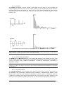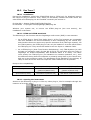
1
USER’S MANUAL 1st edition, August 2011 MINIMOOG-V Version 2.5 ARTURIA – Minimoog-V – User’s Manual 1 Programming: Robert Bocquier Thomas Diligent Nicolas Bronnec Pierre-Jean Camilieri Sylvain Gubian Xavier Oudin Gilles Pommereuil Cédric Rossy Vincent Travaglini Graphics: Morgan Perrier Yannick Bonnefoy (Beautifulscreen) Thomas & Wolfgang Merkle (Bitplant) Manual: Robert Bocquier Thomas Diligent Pierce Warnecke Tomoya Fukuchi Jean-Michel Blanchet Houston Haynes Tom Healy Xavier Oudin Gilles Pommereuil David Poncet Mitsuru Sakaue Noritaka Ubukata Antoine Back Sound-designers: Jean-Michel Blanchet Clay Duncan Celmar Engel Mateo Lupo Chris Pittman Klaus Peter Rausch Klaus Schulze Scot Solida Noritaka Ubukata Katsunori Ujiie Thomas Koot Very special thanks to: Robert A. Moog, Michael Adams, Houston Haynes Thanks to: Steve Dunnington, Randy Fuchs, Roger Luther (moogarchives.com), François Haÿs, Mark Vail, and the numerous beta testers. © ARTURIA S.A. – 1999-2011 – All rights reserved. 4, Chemin de Malacher 38240 Meylan FRANCE http://www.arturia.com Information contained in this manual is subject to change without notice and does not represent a commitment on the part of Arturia. The software described in this manual is provided under the terms of a license agreement or non-disclosure agreement. The software license agreement specifies the terms and conditions for its lawful use. No part of this manual may be produced or transmitted in any form or by any purpose other than purchaser’s personal use, without the express written permission of ARTURIA S.A. moog® and minimoog® are registered trademarks in the UK to Alex Winter. In all other countries Moog® and Minimoog® are registered trademarks of Moog Music Inc. Other products, logos or company names quoted in this manual are trademarks or registered trademarks of their respective owners. 2 ARTURIA – Minimoog-V – User’s Manual TABLE OF CONTENTS 1 WHAT'S NEW IN MINIMOOG V 2.5........................................................................................................ 6 2 FROM THE FIRST MOOG SYNTHESIZERS UP TO TAE ................................................................... 7 2.1 THE GENESIS OF THE MINIMOOG SYNTHESIZER ........................................................................ 7 2.2 A BETTER EMULATION THANKS TO TAE® .................................................................................. 11 2.2.1 Aliasing-free oscillators: ............................................................................................................... 11 2.2.2 Better reproduction of analog waveforms: .................................................................................... 11 2.2.3 Better reproduction of analog filters ............................................................................................. 13 2.2.4 Implementation of the soft clipping ............................................................................................... 14 3 INSTALLATION ........................................................................................................................................ 15 3.1 3.2 WINDOWS INSTALLATION (2000, XP, VISTA) ..................................................................................... 15 MAC OS X INSTALLATION .................................................................................................................... 17 4 AUTHORIZATION .................................................................................................................................... 18 5 QUICK START ........................................................................................................................................... 22 5.1 USING THE PRESETS ................................................................................................................................ 22 5.1.1 Modifying this preset ..................................................................................................................... 23 5.2 THE PLAYING MODES.............................................................................................................................. 25 5.3 OVERVIEW OF THE “CLASSIC” MODE...................................................................................................... 27 5.4 THE “EXTENDED” MODE ........................................................................................................................ 28 5.4.1 The modulation matrix................................................................................................................... 28 5.4.2 The LFO......................................................................................................................................... 29 5.5 THE ARPEGGIATOR SECTION ................................................................................................................... 30 5.6 THE EFFECTS SECTION ............................................................................................................................ 30 5.6.1 The chorus ..................................................................................................................................... 30 5.6.2 The delay ....................................................................................................................................... 31 5.7 THE REAL TIME CONTROLLERS AND MIDI ASSIGN ................................................................................. 31 6 THE INTERFACE ...................................................................................................................................... 34 6.1 USE OF PRESETS ..................................................................................................................................... 34 6.1.1 Choice of a bank, sub-bank, preset................................................................................................ 34 6.1.2 Creation of a bank, sub-bank, preset............................................................................................. 36 6.1.3 Saving a user preset....................................................................................................................... 36 6.1.4 Import/ Export of a bank of presets ............................................................................................... 36 6.2 THE SOUND MAP ..................................................................................................................................... 37 6.2.1 Opening the sound map ................................................................................................................. 39 6.2.2 The sound map interfaces .............................................................................................................. 40 6.2.2.1 6.2.2.2 6.2.2.3 6.2.2.4 6.2.2.5 6.2.2.6 The sound map main interface....................................................................................................................40 The Sound Map overview ..........................................................................................................................41 The instrument type filter window .............................................................................................................42 Preset snap shot memories..........................................................................................................................43 The “Morphing” interface ..........................................................................................................................43 The list preset manager...............................................................................................................................45 6.3 USE OF CONTROLLERS ............................................................................................................................ 46 6.3.1 Potentiometers ............................................................................................................................... 46 6.3.2 Switches ......................................................................................................................................... 46 6.3.3 Pitch Bend wheel ........................................................................................................................... 46 6.3.4 Virtual keyboard ............................................................................................................................ 47 6.3.5 MIDI control.................................................................................................................................. 47 6.3.5.1 6.3.5.2 6.3.5.3 6.3.5.4 6.3.5.5 6.3.5.6 7 Learn menu.................................................................................................................................................47 Assigning MIDI controls............................................................................................................................47 Manage configurations ...............................................................................................................................48 Minimum and maximum bounds................................................................................................................49 Multiple assigned parameter.......................................................................................................................49 Tricks .........................................................................................................................................................50 THE SYNTHESIZER ................................................................................................................................. 51 7.1 7.2 7.3 THE OSCILLATORS .................................................................................................................................. 52 THE MIXER ............................................................................................................................................. 53 THE FILTER AND ITS ENVELOPE .............................................................................................................. 54 ARTURIA – Minimoog-V – User’s Manual 3 7.4 THE OUTPUT VOLUME AND ITS ENVELOPE ..............................................................................................55 7.5 THE POLYPHONIC MODE, THE PLAYING MODES .......................................................................................56 7.6 THE PITCH BEND AND MODULATION WHEELS .........................................................................................57 7.7 THE MOTION RECORDER ........................................................................................................................58 7.7.1 The Motion Recorder activation/deactivation................................................................................58 7.7.2 Playing recorded Motion curves....................................................................................................58 7.7.3 Recording a parameter motion curve in real time .........................................................................59 7.7.4 Erasing a recorded automation in real time ..................................................................................59 7.7.5 Quantizing a motion curve.............................................................................................................59 7.7.6 Setting the modulation amount of a motion curve..........................................................................60 7.7.7 The parameters available for the Motion Recorder.......................................................................60 7.7.8 Editing a motion curve...................................................................................................................61 7.7.8.1 7.7.8.2 7.8 7.9 7.10 7.11 7.12 8 The Edit tools............................................................................................................................................. 61 The Curve Editor screen ............................................................................................................................ 62 THE VOCAL FILTER ..................................................................................................................................62 THE LOW FREQUENCY GENERATOR .........................................................................................................64 THE MODULATION MATRIX .....................................................................................................................64 THE ARPEGGIATOR .................................................................................................................................65 THE CHORUS AND STEREO DELAY ...........................................................................................................66 THE BASICS OF SUBTRACTIVE SYNTHESIS ....................................................................................67 8.1 THE THREE MAIN ELEMENTS ...................................................................................................................67 8.1.1 The oscillator, or VCO...................................................................................................................67 8.1.1.1 8.1.1.2 8.1.1.3 8.1.1.4 8.1.1.5 8.1.1.6 8.1.2 8.1.3 8.1.4 8.1.4.1 8.1.4.2 Triangle...................................................................................................................................................... 68 Sawtooth .................................................................................................................................................... 68 Square ........................................................................................................................................................ 69 Pulse Width Modulation ............................................................................................................................ 69 Synchronization ......................................................................................................................................... 69 Frequency modulation ............................................................................................................................... 70 The noise module ...........................................................................................................................70 The Mixer.......................................................................................................................................71 The filter or VCF............................................................................................................................71 The cut-off frequency ................................................................................................................................ 71 The resonance ............................................................................................................................................ 72 8.1.5 The amplifier or VCA.....................................................................................................................72 8.2 OTHER MODULES ....................................................................................................................................73 8.2.1 The keyboard..................................................................................................................................73 8.2.2 The envelope generator..................................................................................................................73 8.2.3 The low frequency oscillator..........................................................................................................74 9 A FEW ELEMENTS IN SOUND DESIGN...............................................................................................76 9.1 SUBTRACTIVE SYNTHESIS .......................................................................................................................76 9.1.1 A simple bass sound .......................................................................................................................76 9.1.2 A 3 oscillator lead sound ...............................................................................................................78 9.1.3 A polyphonic accompaniment ........................................................................................................79 9.2 THE MODULATION MATRIX .....................................................................................................................80 9.2.1 Using the arpeggiator ....................................................................................................................82 9.3 THE EFFECTS OF THE MINIMOOG V .........................................................................................................83 9.3.1 The stereo chorus...........................................................................................................................83 9.3.2 The stereo delay .............................................................................................................................84 10 MODES OF USE OF THE MINIMOOG-V..........................................................................................86 10.1 STANDALONE .........................................................................................................................................86 10.1.1 Launching the application .............................................................................................................86 10.1.2 Configuration of an instrument: the tool bar.................................................................................86 10.1.2.1 10.1.2.2 10.1.2.3 Configuring Audio and MIDI................................................................................................................ 86 Configuring Skin ................................................................................................................................... 86 Configuring Knob Mode ....................................................................................................................... 87 10.1.3 Panic ..............................................................................................................................................87 10.1.4 Information on rate of processor use.............................................................................................87 10.2 VST™....................................................................................................................................................87 10.2.1 Installation .....................................................................................................................................87 10.2.1.1 10.2.1.2 4 For Windows ......................................................................................................................................... 87 For Mac OS X ....................................................................................................................................... 87 ARTURIA – Minimoog-V – User’s Manual 10.2.2 Using the instrument in VST mode ................................................................................................ 87 10.2.3 Connection to a MIDI track........................................................................................................... 87 10.2.4 Saving presets ................................................................................................................................ 88 10.2.5 Automation .................................................................................................................................... 88 10.3 PRO TOOLS™ ......................................................................................................................................... 89 10.3.1 Installation..................................................................................................................................... 89 10.3.2 RTAS and HTDM standards .......................................................................................................... 89 10.3.3 Opening the instrument ................................................................................................................. 89 10.3.4 Connection to a MIDI node ........................................................................................................... 90 10.3.5 Saving presets ................................................................................................................................ 90 10.3.6 Automation in Pro Tools................................................................................................................ 90 10.4 DIGITAL PERFORMER™ ......................................................................................................................... 91 10.4.1 Installation..................................................................................................................................... 91 10.4.2 Opening the instrument ................................................................................................................. 91 10.4.3 Connection to a MIDI node ........................................................................................................... 91 10.4.4 Saving presets ................................................................................................................................ 91 10.4.5 Automation .................................................................................................................................... 92 ARTURIA – Minimoog-V – User’s Manual 5 1 WHAT'S NEW IN MINIMOOG V 2.5 Minimoog V 2.5 includes the following new features: • Support for 64-bit VST and Audio Unit • Improvement for MIDI assignment o MIDI assignment configurations can be saved and restored o Controls can be assigned to multiple parameters o Minimum and maximum bounds for an assigned parameter o Support for NRPN MIDI controls • Triangle waveform LFO • Look and feel of toolbar updated • Bug fixes System requirements: • MAC OSX 10.5 and 10.6 Intel o PPC no longer supported o MAC OSX 10.4 no longer supported • Windows o Seven o Vista o XP 6 ARTURIA – Minimoog-V – User’s Manual 2 FROM THE FIRST MOOG SYNTHESIZERS UP TO TAE “Mind you, neither of us had any idea where this was leading”* 2.1 THE GENESIS OF THE MINIMOOG SYNTHESIZER Robert A. Moog was born in May 1934 in New York. With a passion for music (he took piano lessons for 12 years), he was introduced to electronics by his father, an engineer. During his adolescence he discovered the Thereminvox plan, invented during the 1930’s by a Russian engineer, Leon Theremin (or more exactly Lev Sergeivitch Termen). Seduced by this instrument with its never before heard sounds, he began to produce his own models and founded his own company in 1954. Frequenting musical professionals, and in particular electronic and concrete music, Moog realized that there was a real demand for electronic instruments of a higher quality. One of the first clients to come to Robert Moog, the professor of music Herbert A. Deutsch, asked him to listen to a song he had composed. Moog was immediately convinced and they decided to associate their work. Their co-operation produced the first voltage controlled oscillator (VCO). In 1964, the first prototype of a Moog synthesizer was produced. It was a modular system with a voltage controlled filter (VCF), an envelope generator, a white noise generator, a trigger and two keyboards each with a generator module (sawtooth, triangle and square) as well as a voltage controlled amplifier module (VCA). A second prototype, grouping those new modules all together, was built during summer 1964 and shown at the AES (Audio Engineering Society) autumn show, where Moog took advantage of an unused stand. In 1965, upon the success encountered at this show, Moog decided to release the 900 series for sale. The R.A. Moog Company at Trumansburg, NY Courtesy of Roger Luther, MoogArchives.com In 1967, Moog decided to release different machines, each with a certain number of modules. This marked the birth of modular systems I, II and III. In 1968 worldwide recognition came with the success of “Switched-On Bach” by W. Carlos. This album, in which classical music is played on a Moog, sold over one million copies and won 3 Grammy awards. *: Bob Moog, quoted by Mark Vail, in his book Vintage Synthesizers © Miller Freeman 1993 ARTURIA – Minimoog-V – User’s Manual 7 The modular system III (1967) Courtesy of Roger Luther, MoogArchives.com Success grew, and big groups like Tangerine Dream, the Beatles and the Rolling Stones would also become modular Moog owners. In 1969, the company which at that time had around 40 employees was building up to 3 modulars per week and the order book was always full. The modular synthesizer series had 5 years of high sales, and sold around 200 models in the United States*. However, the sales would rapidly decrease, because the gigantic proportions of modular units put a damper on the interest of most musicians and also prevented the instrument from entering most music shops, and therefore from being known. Furthermore, a serious competitor, ARP, has just arrived on the market. At the same time, Bob Moog received requests for a more compact instrument that could be transported more easily, directed more to the stage than the studio. With the help of an engineer from Berkeley, Jim Scott, and the advice from numerous musicians he was about to create another legendary synthesizer: the Minimoog… “Here it is! A compact, moderately priced electronic music synthesizer designed for live performance.” This is the way the Minimoog was introduced on the very first promotional brochure, in 1971. The Minimoog synthesizer required several months of research and development and 4 prototypes, before leading to the commercial model. More than 12,000 units were sold until 1981. They were quite far from the 10 modular units per month that Moog Music produced in the late 60’s. *: In 2003, Arturia released a software emulation of the famous modular Moog synthesizers under the name of Moog Modular V. 8 ARTURIA – Minimoog-V – User’s Manual Moog synthesizers sales figures - 1967-1971 Courtesy of Roger Luther, MoogArchives.com The very first Minimoog prototype was called Model A. Three other versions, B, C and D, followed. This last model is the final and most common incarnation of the Minimoog synthesizer and the only one that was put into production in large numbers. The choice of wood rather than plastic for the cabinet prevailed from the beginning, simply because Robert Moog preferred to follow the advice of musician friends, rather than drawings coming from Moog’s industrial engineers. The Model D was first introduced at the NAMM convention in June 1971. It was Moog’s first exposure to the music instruments industry - and the industry's first exposure to synthesizers. The reception was rather cold as, according to Robert Moog himself, “Most dealers didn't know what to make of a musical instrument with words like Oscillator Bank and Filter printed on the front panel”* Minimoog Model A (prototype) Courtesy of Roger Luther, MoogArchives.com : op. cit. MISSING CITATION**************************************************** ARTURIA – Minimoog-V – User’s Manual 9 Minimoog Model D Courtesy of Roger Luther, MoogArchives.com The Minimoog was an unparalleled success during the 1970’s. Artists and bands like Tangerine Dream, Kraftwerk, Depeche Mode, Keith Emerson, Jean-Michel Jarre, Klaus Schulze, and Rick Wakeman used the synthesizer, notably for the typical sound and its very warm quality, which is excellent for basses and lead sounds. After the production stopped in 1981, there had been several failed attempts to restart production of the Minimoog in the 90’s. With the arrival of computer music technologies, the Minimoog has been very often mimicked as a virtual instrument, with little success. Arturia’s Minimoog-V is the latest avatar, and thanks to the TAE technology, we dare to think it is probably the most accurate Minimoog emulation available on the market. Now, Moog Music Inc. develops a modern version of the Minimoog hardware synthesizer under the name Minimoog Voyager, a new version of the Minimoog that has quite a few innovations in its own right. Moog plate affixed on the very first Minimoog prototypes Moog plate affixed on Minimoog D series Courtesy of Roger Luther, MoogArchives.com 10 ARTURIA – Minimoog-V – User’s Manual 2.2 A BETTER EMULATION THANKS TO TAE® TAE® - standing for True Analog Emulation - is a new technology dedicated to the digital reproduction of analog circuits. When implemented in software code, TAE® algorithms guaranty the respect of hardware specifications. This is why the Minimoog-V offers an unparalleled quality of sound. In detail, TAE® means: 2.2.1 Aliasing-free oscillators: Standard digital synthesizers produce aliasing in high frequencies, and also when using Pulse Width Modulation or FM. TAE® allows the production of totally aliasing-free oscillators in all contexts (PWM, FM…), and at no extra CPU cost. Aliasing Linear frequency spectrum of an existing well-known software synthesizer Linear frequency spectrum of the Moogular oscillator made with TAE® 2.2.2 Better reproduction of analog waveforms: Original analog oscillators used capacitor’s charge and discharge cycles to produce common wave shapes (saw tooth, triangle, square). This means that waveforms were slightly curved. TAE® allows the reproduction of the capacitors discharge. ARTURIA – Minimoog-V – User’s Manual 11 Temporal representation of a waveform on a Minimoog Temporal representation of the waveform from a different Minimoog-like software synthesizer Temporal representation of the Minimoog-V waveform thanks to TAE® In addition, original analog oscillators were unstable. Actually, their wave shape was always slightly different from one period to another. Also, due to analog hardware sensitivities, new period trigger times varied with the temperature and other environmental conditions. TAE® simulates the instability of oscillators, helping to create warmer sounds, often given the affectionate term of “fat”. 12 ARTURIA – Minimoog-V – User’s Manual 2.2.3 Better reproduction of analog filters ® TAE allows the emulation of analog-designed filters in a much more precise way than any existing digital filter. In particular, TAE® has managed to reproduce the legendary Moog 24dB low-pass resonant filter with great respect towards the original. Standard 24dB digital low-pass resonant filter from a typical software synthesizer Very selective 24dB resonance filter of the Minimoog TAE made Moog resonance filter: first 24dB resonant filter to be that selective Comparative response filters ARTURIA – Minimoog-V – User’s Manual 13 2.2.4 Implementation of the soft clipping In analog synthesizers, particularly Moog’s, the resonant filter at the VCA uses a current limiting function, preventing the signal from being too loud (soft clipping). TAE® reproduces this current limiting function, making the sound more natural. It also allows filters to enter self-oscillation like original hardware synthesizers do. Current limiting emulation Low-pass resonant filter Input Output 1,5 1 0,5 -0,5 -1 -1,5 Soft-clipping transfer function 14 ARTURIA – Minimoog-V – User’s Manual 1 0, 8 0, 6 0, 4 0 0, 2 -0 ,2 -0 ,4 -0 ,6 -1 -0 ,8 0 3 INSTALLATION 3.1 WINDOWS INSTALLATION Insert the CD-ROM into the drive. Explore the contents of the CD-ROM, double click on the icon named “Minimoog-V 2.5 Setup.exe”. At the first step of the installation, choose the destination folder for the Minimoog-V installation. By default, it will be installed in the following location on 32-bit systems: C:\Program Files\Arturia\minimoog V And I the following location on 64-bit systems: C:\Program Files (x86)\Arturia\minimoog V You can change the destination with the Browse button. Choose the installation folder The Minimoog-V will be installed as a standalone application. The following stage will let you choose to install the Minimoog-V as a plug-in. To do this, choose the protocol(s) that you wish to use (VST or RTAS). For more information on these protocols, go to Chapter 8. ARTURIA – Minimoog-V – User’s Manual 15 Choice of protocols For the VST protocol, you must choose an installation folder in order for the host application to use the Minimoog-V as a plug-in. If you do not know how to make this choice, go to Chapter 8. Choice of VST plug-in installation folder The installation program now has enough information to complete the installation. When the installation process is completed, please proceed to authorization step (Chapter 3). 16 ARTURIA – Minimoog-V – User’s Manual 3.2 MAC OS X INSTALLATION Insert the CD-ROM into the drive. Explore the contents of the CD-ROM, then double click on the icon named “Minimoog_V_2_5”. Follow these steps: - Read and accept the End User License Agreement, - Select a destination. - When prompted, enter the administrator name and password of your computer in the authentication window. Authentication window The Minimoog-V will then be installed as a standalone application, but also as VST, AU and RTAS plug-ins. The installation program now has enough information to complete the installation. When the installation process is completed, please proceed to authorization step (Chapter 3). ARTURIA – Minimoog-V – User’s Manual 17 4 AUTHORIZATION Now that your Minimoog-V has been installed, you have to authorize the synthesizer. The Minimoog-V 2.5 uses the “Soft-eLicenser” virtual dongle solution. Avoiding the use of a USB port, this system allows using the synthesizer on one machine, which must be connected to the Internet during the authorization process. To transfer your license on another computer, or simply use the Minimoog-V on several computers (one instance at a time), you will need: _ to use one USB-eLicenser hardware dongle (sold separately, also used by many other software editors); _ in the eLicenser Control Center, to drag-and-drop the license from one dongle to the other. This transfer, requiring a valid Internet connection, can be done in both ways: _ from Soft-eLicenser to USB-eLicenser; _ from USB-eLicenser to Soft-eLicenser. Please check the eLicenser documentation installed on your computer for any further technical details. The first step is to register your software in order to obtain the activation code that will enable you to actually use the software. You should have handy the license serial number of Minimoog-V and the unlock code (these are an integral part of the software and are printed on a small plastic card) Connect your computer to the Internet, and go to this web page: http://www.arturia.com/evolution/en/community/my-account.html If you don’t have an Arturia account yet, please create one now: This will send you to this form: 18 ARTURIA – Minimoog-V – USER’S MANUAL If you already have an account, simply log in: One you are logged into your account, you can register your Minimoog-V and request your activation code. Go to the “My Registered Products” section of your account and click on the “Add” button: In the form that appears, select “Minimoog-V” in the drop down menu, and key in your synthesizer serial number and unlock code (as written on the registration card): Next is the confirmation screen: ARTURIA – Minimoog-V – USER’S MANUAL 19 And finally there is a screen from which you can copy the eLicenser activation code. The very same information is sent to you by email as a backup. Now that you have retrieved the activation code, launch the eLicenser Control Center. This application has been automatically installed on your computer along with the Minimoog-V. It is accessible here: Windows: Start > Programs > eLicenser > eLicenser Control Center Mac OS X: Finder > Applications > eLicenser Control Center The following screenshots have been taken using computer running Mac OS X; however the process is strictly identical under a Windows XP/Vista/7 machine. The same functions apply, only the graphical user interface differs, and possibly also the language used. These little details should not prevent you from understanding the full process. In the eLicenser Control Center main window you should see a “SeL” software dongle installed onto your computer. eLicenser Control Center main window, showing an empty Soft-eLicenser. In the eLicenser Control Center menu, click on the “Enter Activation Code” button, and enter the code when prompted. Simply paste in the 32-digit code you’ve just copied from your account on the ARTURIA website: 20 ARTURIA – Minimoog-V – USER’S MANUAL Enter the activation code The eLicenser Control Center is now ready to download the software license that will allow you to use the Minimoog V. Click on Start, the progress bar should advance until download completion. A popup window will confirm, just click “Close”. Now the main eLicenser Control Center window should show your Minimoog-V license installed and activated. License is installed and activated It’s now time to launch the Minimoog-V synthesizer! ARTURIA – Minimoog-V – USER’S MANUAL 21 5 QUICK START This chapter will help you get to know the main aspects of how the Minimoog-V works. You will be presented an overview of the different parts of the synthesizer while using the program for the first time. You will find a detailed description of all visible settings and controllers in the chapters that follow. Chapter 6, “A few elements of sound design”, is specially recommended for users who have never worked with a subtractive synthesizer before and who wish to learn the basics in this domain. TOOLBAR EXTENSION CONTROLLERS FILTER AMPLIFIER OSCILLATORS AMPLIFIER ENVELOPE VIRTUAL KEYBOARD MODULATION WHEELS MIXER Overview of the minimoog V 5.1 USING THE PRESETS Use of presets is one of the major areas of evolution when the Minimoog-V is compared to the original, which couldn’t save sounds! With the Minimoog-V, a preset (memorized sound) contains all of the parameter settings of the synthesizer plus the extension panel and the different real-time effect controllers necessary to reproduce the sound. To get to know a few of the different sounds contained in the Minimoog-V, we will select a simple bass preset. To do this, click on button next to the the “BANK” LCD display (this display shows the name of the current bank in use). When you click, you will see a dropdown menu indicating the available banks. Choose the “J.M.Blanchet” bank. When this menu is open, it expands the sub-menus allowing you to reach the “SUB BANK” and “PRESETS” of a sound designer with a single click. 22 ARTURIA – Minimoog-V – USER’S MANUAL Choose the “SUB BANK” called “Basses” and finally select “JMB_Classic1” in the “PRESETS”. Select the preset JMB_Classic1 The Minimoog-V comes with 400 presets, which will familiarize you with the sounds of the synthesizer. A bank called “Templates” offers a selection of presets with a basic configuration (or template) to start programming a sound. The sound “1_Osc”, for example, comes with: an oscillator directed to the low-pass filter, with the signal then routed to the VCA. It is also possible to see all of the presets corresponding to a given type of sub-bank by choosing the “All” option in the bank. For example, to see all of the bass presets click on “All” in the bank selection and then on “Basses”. 5.1.1 Modifying this preset For this, we will start with a very simple manipulation. Modify the brightness of the “JMB_Classic1” sound using the “Cutoff Frequency” potentiometer of the filter. Turn this potentiometer and you will hear the tone of the sound becoming more or less “bright”. Set this potentiometer to your liking. ARTURIA – Minimoog-V – USER’S MANUAL 23 Change the brightness of the sound In the same manner, you can change the range of oscillator1 by turning the “Range” potentiometer to one of the six values expressed in steps (like on organs). The lower the number, the higher the pitch of the sound. (The standard tuning is found at the value 8’) Setting the range of oscillator 1(“Range”) By performing these first settings, you have already modified the “JMB_Classic1” preset. You can now save the sound that you have just created. To save a “user” preset, click on the save icon on the toolbar: the settings of the current sound will be saved in the selected preset without changing the name. If the current preset is a “factory” preset, the factory preset will not be overwritten. To choose another destination for this sound, click on the “Save as” icon and select a destination. For example, select “New” in the choice of bank. 2 new slots for bank and sub-bank, as well as a new preset, are all immediately created. The names “new bank”, “new sub bank…” and “new preset…” appear in their respective menu locations. Click on each of them to change their names. 24 ARTURIA – Minimoog-V – USER’S MANUAL Saving a preset 5.2 THE PLAYING MODES The Minimoog-V offers 2 playing modes: The “Classic” mode uses the original configuration of the Minimoog. Some additional features: oscillator 2 can be synchronized to the oscillator1, oscillator 2 can be disconnected to the keyboard following circuit, and poly/mono/unison switches have also been added. ARTURIA – Minimoog-V – USER’S MANUAL 25 The Classic mode (the original Minimoog) The “Extended” interface gives access to a motion recorder, a vocal filter, a LFO, a modulation matrix, an arpeggiator and two effects. These different functions will enrich the basic settings of the minimoog V. The panel of the “Extended” mode To access the “Extended” mode, click on the wooden crosspiece situated above the synthesis settings or on the “Open” button on the right of the toolbar. To return to the “Classic” mode, simply click again on the wooden crosspiece or on the “Close” button. Opening the extension panel 26 ARTURIA – Minimoog-V – USER’S MANUAL To use the Minimoog-V exactly like the original Minimoog, you must also deactivate the chorus and delay effects on the toolbar and switch off the polyphony toggle in the output section. 5.3 OVERVIEW OF THE “CLASSIC” MODE The “Classic” mode contains 50 synthesis settings, which will allow you to conceive an infinite variety of sounds. The knobs and switches associated with these parameters are found regrouped on the panel above the keyboard. These parameters are composed of: 3 oscillators (VCO) which deliver the base audio signal thanks to 6 waveforms (triangle, sawtooth 1 and 2, square, rectangle 1 and 2) and manage the pitch of the sound (the frequency). The third can also be used as a modulator when its signal is directed to the filter or oscillators. A Mixer allows you to mix the signals coming from the oscillators or the noise module. A low-pass 24dB resonant filter An ADS envelope modulating the low-pass filters 1 amplifier (VCA) allowing the amplification of the signal coming from the filter to direct it to the stereo output. An ADS envelope modulating the signal going through the amplifier. The synthesis parameters Let’s see how to quickly create a progressive lead: To correctly understand the logic in programming the Minimoog-V, let’s use a very simple sound. Select the preset “1_Osc” (in the “Templates” sub-bank). The structure of synthesis of this sound is very basic: the sawtooth waveform of oscillator1 is active and the signal is routed through the low-pass filter, and then through the output amplifier. The routing of the sound of preset “1_Osc” Start by lowering the cut-off frequency of the low-pass filter (LPF). This will make the sound more and more dampened. To do this, set the “Cutoff” frequency potentiometer. For fine-tuning, use the right mouse button (this is valid for all potentiometers). Notice that the filter cut-off is modulated by an ADS envelope (Attack, Decay and Sustain). ARTURIA – Minimoog-V – USER’S MANUAL 27 To clearly hear the effect produced by the ADR envelope on the filter cut-off frequency, increase the resonance (“Emphasis”) value to 5.00. This will amplify the filtering effect and the sound will start to “ring”. Change the length of attack for this envelope (“Attack time”) so that the brightness increases slower or faster when the note is sent. In the same manner, change the value of decay (“Decay time”); the brightness will diminish faster or slower as you hold the note. The “Attack time” parameter of the filter envelope You will probably have noticed that an envelope also modulates the amplitude of the sound – “Loudness Contour” Increase the “Attack time” so that the volume of the sound increases progressively. Do the same with the “Decay time”; the volume will progressively decay when you hold the note pressed down. Amplitude envelope – “Loudness Contour” 5.4 THE “EXTENDED” MODE When the Minimoog-V is in the “Extended” position, you access an extension panel to the parameters of synthesis. It is displayed in the form of a modulation matrix, a Low Frequency Oscillator (LFO) which was added as a substitution for oscillator 3 which was being used to this effect. An arpeggiator, a chorus and stereo delay complete this extension. 5.4.1 The modulation matrix The modulation matrix multiplies the possibilities for editing sound when compared to the original instrument. You can choose 8 sources (sub osc., envelopes, etc.) to modulate 8 destinations (freq. Osc., freq. VCF, etc.). The choice of source and destination is done via the LCD displays. The matrix offers 15 sources of modulation and 35 destinations (compared to 2 on the original!). The modulation matrix 28 ARTURIA – Minimoog-V – USER’S MANUAL 5.4.2 The LFO On the original Minimoog (equivalent to the “Classic” mode), oscillator3 can be set to the low frequency (“Lo” position in the range) to be used in LFO mode. This removed the possibility of using 3 simultaneous oscillators as well as a slow modulation on the filter cut-off frequency for example. With the added LFO module added in the panel of the “Extended” mode, you can keep the 3rd oscillator as a base for sound and add an additional source of modulation to be used on one of the 35 available locations. Let’s apply 2 additional types of modulation to the “1_Osc” preset: Among the modulation sources, choose the low frequency oscillator (“LFO”). Choose the filter cutoff frequency among the destinations. Turn down the frequency so that you can hear the result. The cutoff frequency will vary in a cyclical way, following the LFO oscillations. Modulation of the filter cutoff frequency by the LFO Between the LCD displays is the “Amount” knob. You can set the modulation level by applying positive (turn to the right) or negative (turn to the left) values. For this example, take a value of 0.0480. Turn the knob to the right to apply a positive value Let’s control the amount of the LFO modulation by using the modulation wheel to control the LFO’s amplitude: Choose the modulation wheel (“Wheel”) among the sources. ARTURIA – Minimoog-V – USER’S MANUAL 29 Choose “LFO AM” among the destinations Set the modulation level by applying a positive value of about 0.0193. Set the modulation wheel up to 0.60. 5.5 THE ARPEGGIATOR SECTION The “Arpeggiator” section lets you easily create an arpeggio from a chord played on the keyboard. An arpeggio is a series of single notes of the same length that spell out a chord, and play one note after the other. Arpeggiator settings are available on the right of the modulation matrix. Let’s take the example the “JMB_Classic2” preset to see how to use the arpeggiator. Click on the “PLAY” button of the arpeggiator. Play a chord between C4 and C6; the notes will be played one after the other in the order you placed them (it is possible to change the order by clicking on the “mode” button). It is also possible to keep the chord held down by clicking on the “HOLD” button. To remove one or several notes, click again on the “HOLD” button and play the note you want to remove. The arpeggiator 5.6 THE EFFECTS SECTION The effects section lets you add chorus or delay to your sound. 5.6.1 The chorus The Chorus effect allows you to double and slightly detune your sound in order to make it deeper and livelier. 3 types of stereo chorus are available. Activate the “ON/OFF” button for Chorus, on the right side of the menu bar. Set the “Dry/Wet” knob for Chorus in order to counterbalance the “raw” sound and use the “feedback” knob to control the feedback of the effect. Next turn the “Rate” knob to set the speed of the oscillations. Finally set the chorus depth by turning the “Depth” knob. You can choose between 3 types of chorus: Chorus 1, 2 and 3, from the simpler version to a more sophisticated chorus, designed for sharper detuning effects. 30 ARTURIA – Minimoog-V – USER’S MANUAL The chorus 5.6.2 The delay The delay effect adds stereo echoes to the sound. It has independent settings for the speed and the number of echoes on the right and left sides. It is also possible to create a great number of rhythmic combinations between the echoes. The speed of the delay can also be synchronized with the MIDI tempo. Let’s keep the “JMB_Classic1” preset and see how to use the delay with this sound: Press the “DELAY” button on the toolbar. The effect is enabled. Set the “Dry/Wet” knob of the Delay so as to balance the “raw” bass sound. Next turn the 2 “Speed” knobs of the delay to set the speed of echoes for the right side (Time Right) and left side (Time Left). It is also possible to set the number of echoes on each side (“Feedb. Right” and “Feedb. Left”) Settings of the delay effect 5.7 THE REAL TIME CONTROLLERS AND MIDI ASSIGN Minimoog-V 2.5 has been improved in order to provide easier access to MIDI assignment, and now has the possibility to save and select multiple configurations. A default configuration matching Arturia Analog Experience keyboards is loaded at startup. Thus you can control Minimoog V 2.5 from Analog Experience keyboards without any configurations. If you own a non-recognized MIDI controller keyboard, configuration is pretty straightforward: Check that your MIDI controller is recognized (in standalone, if not recognized, you can click Settings to configure MIDI inputs) Click on the button Learn in the toolbar ARTURIA – Minimoog-V – USER’S MANUAL 31 “Learn” menu in toolbar Select LEARN entry, Learn mode is then activated Click on the Cutoff Frequency Knob on the GUI MIDI assignment popup A MIDI assignment popup opens, and then just move the control that you want to be assigned. The control is automatically assigned to Cutoff frequency (you can check MIDI control message value). Tweak MIN and MAX sliders to adjust bounds for that control. Repeat this operation for other controls. Notice that you can assign multiple GUI controls to a single hardware control. Click the Learn button and select LEARN entry to switch off Learn mode. Click the Learn button and select Save As to save your configuration Save As popup Now you can find and quickly reload your newly created configuration in the Learn menu 32 ARTURIA – Minimoog-V – USER’S MANUAL “Learn” menu, recall newly created configuration ARTURIA – Minimoog-V – USER’S MANUAL 33 6 THE INTERFACE 6.1 USE OF PRESETS Presets let you memorize the sounds of the Minimoog V. A preset contains all of the information pertaining to the reproduction of a sound. In the program, the presets are classed in “banks” and “sub-banks”. Each bank contains a certain number of sub-banks, which generally determine a type of sound: sub-bank “basses”, sub-bank “sound effects”, etc. Each sub-bank contains within itself a certain number of presets. The Minimoog-V is shipped with several “factory” banks. But it is possible to create new “user” banks of sounds, each containing a number of sub-banks and presets. For security, the “factory” banks cannot be directly modified. It is nonetheless possible to create a sound based on a factory preset by saving it as a “user” preset. 6.1.1 Choice of a bank, sub-bank, preset The bank, sub-bank and preset in use by the Minimoog-V are permanently displayed in the synthesizer tool bar. Display of current bank, sub-bank and preset To choose a preset in the current sub-bank, click on the right most button, and a dropdown menu appears with a list of the presets of the same sub-bank. You can choose another preset by selecting the corresponding line in the dropdown menu. As soon as the preset has been chosen, you can play the new sound on your MIDI keyboard or from your sequencer. Choose a preset in the same sub-bank To choose a preset in the same main bank, but a different sub-bank, click on the middle button, and a dropdown menu appears with a list of the sub-banks contained in the same main bank. Each sub-bank listed in the menu allows you to open a sub-menu containing its presets. A click on a preset allows you to directly choose a preset in the new sub-bank. 34 ARTURIA – Minimoog-V – USER’S MANUAL Choice of a preset in another sub-bank To choose a preset in another main bank, click on the left most button. A dropdown menu appears with a list of the main banks available with the sub-banks corresponding to the sub-banks defined in each main bank and to the presets contained in each subbank. You can thus freely choose a preset by clicking on its name. Choice of a preset in another main bank In the “BANK” dropdown menu, the “All” option allows you to open a sub-list with all of the sub-banks available in all of the banks. This gives you access directly to all of the presets of a given type, for example all of the basses, no matter which bank they are in. This function is particularly useful to quickly see all of the presets of the same type. Choice of preset regardless of bank ARTURIA – Minimoog-V – USER’S MANUAL 35 When a preset has been modified an asterisk appears next to its name in the tool bar. 6.1.2 Creation of a bank, sub-bank, preset To create a new bank, click on the left button. The dropdown menu displays the names of all of the existing banks of sounds, and a line called “New bank...”. Click on “New bank...” to create a new bank of sounds. You can then change the name of this bank by clicking on its name in the tool bar and entering the new name. To create a new sub-bank, just click on the middle button, and select “New subbank...”. You can also change the name of the new sub-bank. Finally, to create a new preset, click on the right button, and select “New preset...”. The new preset is created, recording the current settings of the minimoog V. You can thus work on the settings of a sound, and save the sound again with the same preset name by clicking on the save button (see the following paragraph). You can also change the title of the new preset by clicking on its name. 6.1.3 Saving a user preset To save your setting modifications in the current preset, click on the “Save” button in the tool bar of the Minimoog V. “Save” button in the tool bar If you want to save your settings under another preset name, click on the “Save As” button in the tool bar. A dropdown menu appears and lets you choose an existing preset (in this case, the contents of the existing preset will be replaced with the current settings), or else lets you save your settings as a new preset (in this case, click on “New preset...” in the sub-bank of your choice). “Save As” button and save menu in the tool bar When you are working from a factory preset, which cannot be deleted, clicking on the “Save” button will not replace the current factory preset, but will instead automatically open the “Save As” menu to save the current settings as a user preset. 6.1.4 Import/ Export of a bank of presets It is possible to import new banks of presets conceived for the Minimoog V. To import a new bank of presets, click on the preset bank import button on the tool bar: Preset bank import button on the tool bar 36 ARTURIA – Minimoog-V – USER’S MANUAL When you click on this button, a window will appear allowing you to choose the preset bank file for the Minimoog-V (“.minibank” extension). Choose the file that you want to import, and click on “Open”. The new bank of presets will automatically appear among the available banks. The Minimoog-V equally offers the possibility to export your own sounds to save them, to use them on another machine, or to make them available to other users. It is possible to export a preset, a sub-bank, or a complete bank. To export the current bank, sub-bank, or preset, click on preset bank export button in the tool bar of the program: T Current preset bank export button in the tool bar Select the type of export that you want to perform (bank, sub-bank or preset) and a window will appear, giving you access to a choice of destination folder and file name for the bank that you are exporting. 6.2 THE SOUND MAP The sound map is an innovative preset explorer, which offers an easy and fun way to locate and choose a preset on a map area to simplify the preset management and to quickly find the appropriate sounds. The sound map also offers a brand new interface for creating new sounds thanks to a morphing feature between four presets. The main interface of the Sound map ARTURIA – Minimoog-V – USER’S MANUAL 37 The Sound Map offers three options: The sound map: the sound map classifies the presets thanks to statistic methods in order to organize the sounds on a map from their own audio characteristics. The Map interface The Presets list: this page offers a more classical interface to classify the presets using lists and filters to find the desired sound. The List interface The Morphing interface (COMPASS): this page allows creating new sounds in real time thanks to a morphing result between 4 presets. 38 ARTURIA – Minimoog-V – USER’S MANUAL The Morphing interface Let’s go more deeply into the different sound map interfaces… 6.2.1 Opening the sound map To open the main Sound Map interface, click on the “SOUND MAP” button located on the tool bar. A new window appears over the Minimoog-V main interface. Open the main Sound Map interface To open the preset list page, click on the “LIST” button, on the top right of the sound map interface Open the List interface To open the preset morphing page, click on the “COMPASS” button. Open the Morphing interface ARTURIA – Minimoog-V – USER’S MANUAL 39 To return back on the main sound map interface, click on the “MAP” button Return back on the map interface 6.2.2 The sound map interfaces 6.2.2.1 The sound map main interface The sound map interface shows a map where are shared out all the presets of the Minimoog-V organized for their types of sound and their own audio characteristics. The types of presets are represented by different geometrical characters and colours for an easy way to locate them: The “Bass” sounds The “Brass” sounds The “EFX” sounds The “FM” sounds The “Guitar” sounds The “Keyboard” sounds The “Lead” sounds The “Pad” sounds The “Percussive” sounds The “Sequence” sounds The “Strings” sounds The “Others” sounds To select and listen a preset, directly click on one of the icons, anywhere you want on the map area. The icon is now highlighted in red. If you hold a few seconds on the selected preset, a popup appears and indicates the name of the preset. 40 ARTURIA – Minimoog-V – USER’S MANUAL Select a preset You can create new presets thanks to an exclusive real time morphing feature: Click between a group of presets and hold the left button of the mouse on this point. Four red arrows drawing a cross appear linking the group of four presets. Morphing between a group of presets You can now drag your mouse between those presets. The green arrow shows you the starting point of your motion. When you release the left mouse button, you can play the resulted sound and, if you wish, you can save it on a User bank of the Minimoog-V memory. In this way it is very easy to quickly get some new and exiting sounds without programming anything on the synthesizer interface. 6.2.2.2 The Sound Map overview On the top right of the Sound Map main interface, you can see an overview of this map. You can use the map overview for navigating into the map and to zoom in or out inside of the map area. ARTURIA – Minimoog-V – USER’S MANUAL 41 The map overview interface To navigate into the map, click inside of the red square and drag it on the map area to view other sections of the Sound map. To zoom in the view on the sound map, click on the “Zoom” slider, under the overview window, and drag it on the right to increase the size of the map. To zoom out the view on the sound map, click on the “Zoom” slider, and drag it on the left to decrease the size of the map. The zoom slider You can also use the “Zoom +” or “Zoom -” buttons, under the slider, to increase or decrease the map size step by step (by factor 1). Clicking on the “FIT zoom” button resizes the map to its global size. The FIT ZOOM button 6.2.2.3 The instrument type filter window On the right of the map main interface, an instrument type filter window allows you to choose which type of preset you want to see (or to hide) on the map. By default, all types of presets are selected. The instrument type filter To select an individual or a group of instrument types: 42 ARTURIA – Minimoog-V – USER’S MANUAL First click on the “All” button, on the bottom of the type filter window: this will hide all the instrument types from the sound map. The ALL button Then, select the type(s) you want to see by clicking on the corresponding square box(es). A square appears on the selected box(es) and the type(s) of preset appears on the map interface. Show pad presets This is a good way to simplify and to refine the preset search. If you click again on the “All” button, all the types of presets will be displayed on the map. 6.2.2.4 Preset snap shot memories You can select up to four presets, anywhere on the map interface, and save them on up to four snap shot memories. You will be able to use those four presets on the “Morphing View” (see below for more details) to create new sounds by using the morphing feature. Of course, you can save any kind of type of presets on these four snapshot memories. Select a snapshot memory To save a preset on a snapshot memory: Select a preset on the sound map main interface. Hold the “Shift” key and select one of the four snapshot memory button. The snapshot memory button is now highlighted in red. Repeat the same actions if you wish to save presets on the three other snapshot memories. If all memories already contain a saved preset, you can replace them with other presets: Select another preset anywhere on the Sound Map interface, click on any of the 4 snapshot buttons while pressing the Ctrl key. 6.2.2.5 The “Morphing” interface The “Morphing” page is an independent module allowing you to quickly create some new sounds thanks to a real time morphing from the four selected presets saved on the snapshot memories. The four presets are placed on the four cardinal points of the compass. ARTURIA – Minimoog-V – USER’S MANUAL 43 The Morphing interface To open the “Morphing” page, click on the “COMPASS” button, situated on the toolbar of the Sound map. To create a new morphed sound from those presets: Click anywhere on the center of the compass area (four red arrows appear converging to the group of presets) Hold the left button of your mouse and drag the convergence point until you find a good sound. The green arrow shows you the starting point of your motion. 44 ARTURIA – Minimoog-V – USER’S MANUAL Create a new sound If you wish, you can save it on a User bank of the Minimoog-V memory. 6.2.2.6 The list preset manager The list preset manager offers a more classical way to explore the presets using a list interface in which the Presets are classified and filtered in order to simplify preset management. Preset list interface To open the list interface, click on the “List” button, situated on the toolbar of the Sound map. Click on the “List” button The list preset interface is very simple: you can see three columns showing, from left to right: • The preset names • The instrument type • The name of the sound designers All this data is classified in alphabetical order. To select a preset, simply browse the list and click on the name of a desired preset. You can inverse the order (from A to Z or from Z to A) by clicking on the column title: an ascending or descending arrow shows you the order type. ARTURIA – Minimoog-V – USER’S MANUAL 45 Inverse the order of the instrument types 6.3 USE OF CONTROLLERS The Minimoog-V uses different types of controllers: potentiometers, switches, wheels, etc. Let’s take a look at those different types of controllers: 6.3.1 Potentiometers Generally host sequencers offer several potentiometer control modes. The default mode of control for knobs with the mouse is the circular mode: click on the knob and turn around it in order to change the value of the controller. The circular mode gives high precision in the manipulation of controls: The further the mouse goes from the knob, the higher the precision of the setting. Potentiometer In linear mode, the knob can be set only by vertically moving the mouse, not going around it. Like the sliders, it is possible to obtain a higher precision by right clicking or Shift+Click on the knob concerned. The linear mode can sometimes be simpler to use than the circular mode, although we can lose precision (the precision is limited by the number of vertical pixels on the screen on which the mouse movements are being evaluated). Movement in linear mode is available in the options of your sequencer. In Cubasetm, for example, this choice can be found via the “Edit/Preferences” menu, and is found in the “General” tab of the window. 6.3.2 Switches The Minimoog-V has several types of switches. Simply click on these switches to change their state. Switches 6.3.3 Pitch Bend wheel The pitch bend wheel is used to change the pitch of the oscillators. Just click on the wheel and move the mouse up or down to change the pitch of your sound. The wheel goes back to the center position when the mouse is up. 46 ARTURIA – Minimoog-V – USER’S MANUAL The pitch wheel 6.3.4 Virtual keyboard The keyboard lets you listen to the synthesizer sounds without the need for an external master MIDI keyboard, and without programming a melody in the sequencer. Just click on a virtual key to hear the corresponding sound. 6.3.5 MIDI control Most of the knobs, sliders and switches on the Minimoog-V can be manipulated with external MIDI controllers. Before anything else, make sure that the MIDI device that you wish to use is correctly connected to the computer, and that the sequencer or the Minimoog-V application is correctly configured to receive MIDI events coming from the device. 6.3.5.1 Learn menu A new menu entry has been introduced in Minimoog V 2.5. This menu entry “Learn” provides access to MIDI assignment functionalities. “Learn” Menu The “Learn” Menu is composed of 2 sections: First section provides • “Learn” Mode activation and deactivation • “Save” current configuration • “Save As” current configuration to a new one • “Remove” current configuration from list The second section contains the list of existing configurations • The ticked one is the current one • Click on a configuration to load it 6.3.5.2 Assigning MIDI controls In order to start assigning MIDI controls, click the “Learn” menu, then the “LEARN” entry. The entry menu button remains highlighted to indicate that the “learn mode” is ON. Click on a controller of the GUI to open the MIDI assignment popup. ARTURIA – Minimoog-V – USER’S MANUAL 47 Plug-in parameter name Assigned or not Control number MIDI assignment popup Learn assignment The first and easiest way to assign a control is to move it for it to be recognized by Minimoog V. Hand assignment It is also possible to change the assigned MIDI control number by clicking on Control#xx and select another value. Support for NRPN In addition to MIDI Control Change messages, NRPNs are now supported: either send NRPN MIDI control messages to Minimoog V, or check NRPN, then select LSB# and MSB# numbers: MIDI assignment popup, NRPN activated Remove assignment Assignments can be removed by clicking the “Clear” button. The message “Not assigned” will then be displayed. All these operations deal with a single plug-in parameter. In order to setup a complete configuration, a set of parameters should be configured. 6.3.5.3 Manage configurations New in Minimoog V 2.5: the possibility to maintain multiple configurations. Default configuration By default, Minimoog V loads configuration for Arturia Analog Experience keyboards. Select one configuration A configuration is loaded by clicking the entry in “Learn menu”. Create a new configuration A new configuration can be created by performing assignment operations described in the previous section. This configuration has to then be saved by clicking on the “Learn menu”, “Save As” entry. A popup opens: enter the name of your configuration. A new entry for your configuration now exists in the list of available configurations. Remove a configuration 48 ARTURIA – Minimoog-V – USER’S MANUAL It is possible to remove a configuration by loading it and then clicking on “Remove”. 6.3.5.4 Minimum and maximum bounds For each assignment, a minimum bound value and a maximum bound value can be set. This means that: The assigned parameter will have the configured minimum value when the controller will be at its lowest position Assigned parameter will have the configured maximum value when the controller will be at its highest position You can invert (Negative Slope) Min and Max so that parameter will have minimum value when control has the highest value, and parameter will have maximum value when control has the lowest value Output parameter values MAX Input control values MIN DEFAULT Output parameter values Output parameter values MAX Input control values MIN POSITIVE SLOPE MIN MAX Input control values NEGATIVE SLOPE parameter_value = MIN + (MAX – MIN) * control_value 6.3.5.5 Multiple assigned parameter It is possible to assign and setup assignment for multiple parameters for a single control. Activate “Learn” mode, select a parameter (GUI control) Tweak control to assign it (optionally setup minimum and maximum) Select a second parameter And tweak the same control Deactivate “Learn” mode Tweaking assigned control should modify both parameters with regards to assignment setup (Min, Max). ARTURIA – Minimoog-V – USER’S MANUAL 49 6.3.5.6 Tricks Oscillator 2 and 3 tune control 2 parameters: FINE and COARSE. If “Learn” mode is ON, clicking on control provides access to the assignment of the FINE parameter, shift+clicking on control provides access to assignment of the COARSE parameter. 50 ARTURIA – Minimoog-V – USER’S MANUAL 7 THE SYNTHESIZER When it is set to “Classic” mode, the Minimoog-V remains very close to the original synthesizer. It is composed of two parts, one containing the synthesis parameters, the other being the keyboard and the modulation wheels. The synthesis panel is separated into several sub-groups, corresponding to the usual modules for subtractive synthesis: Oscillators, Mixer, Filter and Envelopes. View of the Minimoog-V in “Classic” mode By clicking on the “Open” button of the toolbar or the upper wooden bar, the Minimoog-V will open and reveal the extension panel. The effects, an arpeggiator and a modulation matrix are contained here. ARTURIA – Minimoog-V – USER’S MANUAL 51 View of the Minimoog-V in “Extended” mode 7.1 THE OSCILLATORS The Minimoog-V has three independent oscillators, which can be found in the “Oscillator Bank” section in the synthesis panel. Oscillators Each of these oscillators can produce different waveforms, which are selected using the knob on the right. The first two generate, from left to right, a triangle, an asymmetric triangle, an ascending sawtooth, a square, asymmetric square and impulse. The third oscillator replaces the asymmetric triangle with a descending sawtooth. By right clicking on these selectors, it is possible to adjust the impulse width of certain waveforms: 52 ARTURIA – Minimoog-V – USER’S MANUAL square, rectangular, impulse, triangle and asymmetric triangle. If the waveform is again modified, the impulse width will go back to its default value. The choice of range for these oscillators can be set with “Range” knobs on the left. From the left to right are the positions: Low, 32, 16, 8, 4, and 2, the third oscillator adds the “LowMono” position at the extreme left. The “Low” position corresponds to a very low frequency mode, the position “LowMono” on the third oscillator adds a monophonic function. In this mode, the oscillator will generate the same signal irrespective of the note played, unlike the “Low” mode where it generates a different signal for each of the notes in polyphonic mode. The other positions of this knob correspond to the range, the 8 position being the position without transposition, positions 4 and 2, respectively 1 and 2 octaves above, positions 16 and 32 respectively 1 and 2 octaves below. Oscillators 2 and 3 can equally be fine tuned with the central “Frequency” knob. By left clicking with the mouse on the knob, tuning is done by semi-tones, by up or down an octave. When right-clicked, it is possible to tune it in a continuous manner, by more or less a semi-tone. By double clicking on this knob, it is possible to set it to its default value, which is to say tuned. • The “Sync” switch synchronizes oscillator 2 with oscillator 1. In this position, it is the tuning of oscillator 1 which will give the pitch while oscillator 2 will bring and modify the harmonics heard. • The “Osc. 2 Control” switch allows to activate and deactivate the command of oscillator 2 by the keyboard. • The “Osc. 3 Control” switch is for activating and deactivating the command of oscillator 3 by the keyboard. • The “Oscillator Modulation” switch modulates oscillators 1,2 and 3 via oscillator 3 with an amplitude that is dependant on the modulation wheel. If we don’t want to have oscillator 3 modulate itself, we need to deactivate the switch. 7.2 THE MIXER The section situated on the right of the “Oscillator Bank” sub-group mixes the different signals available before applying the filtering. Mixer There are five sound sources available: the three oscillators, a noise generator and external audio in. The level of the three oscillators is set with each of the “Volume” ARTURIA – Minimoog-V – USER’S MANUAL 53 knobs, the external signal level with the “External Input Volume” knob, the noise level with the “Noise Volume” knob. The five vertically aligned switches allow the quick deactivation of a given sound source, while the “White/Pink” switch selects a white or pink noise. When the “Overload” indicator lights up, this indicates an overload of the external audio in. The mixer possesses two modes of functioning, with or without the emulation of the overload circuit. In the first case, the sound signals are not modified regardless of their level. In the second, the overload circuit limits the amplitude and thus allows a modification of the tone typical of the original Minimoog. The mixer mode change is done with the “Soft Clipping” switch on the far right of the synthesis panel. It should be noted that the emulation of the overload circuit is heavy on calculation power, and using it should be avoided with heavy polyphony or unison. Activation of the overload circuit (soft clipping) The switch corresponding to the external signal has three positions. The first disconnects this input from the mixer. The second position connects the output of the Minimoog-V to the mixer. This allows, thanks to the particular distortion brought by the overload circuit, to obtain a typical sound. The third connects the external input to the mixer. 7.3 THE FILTER AND ITS ENVELOPE The result of mixing different sources of sound is directed towards a resonant filter with a slope of 24dB per octave. Filter parameters The “Cutoff frequency” knob sets the cut-off frequency. The “Emphasis” knob sets the level of resonance and “Amount of Contour” sets the action of the envelope generator associated to the filter. It should be noted that this filter auto-oscillates, which is to say that when the resonance is set to the maximum, the filter generates a signal close to sinusoid even in the absence of an input signal. Nonetheless, a weak noise signal as filter input brings us a little closer to the results obtained with the original Minimoog. In fact, electronics can never guarantee a perfect zero level to the filter input as is the case with a virtual reproduction. 54 ARTURIA – Minimoog-V – USER’S MANUAL Envelope generator associated to the filter The envelope generator associated to the filter can be adjusted with the “Attack Time” knob for the attack time, and the “Decay Time” knob for the decay time, and the “Sustain Level” knob for the level of sustain. Unlike other envelope generators, there is no separate setting for the time to return to zero. This time is the same as the decay time but can be activated or deactivated with the “decay” switch situated on the left of the keyboard. When it is deactivated, the return time to zero for the generator is practically zero. The two “Keyboard control” switches allow the use of a key follow on the filter cut-off frequency. • When they are set to the “OFF” position, no key follow is connected. • When the first is “ON”, the key follow allows the modification of the cut-off frequency by a major third for an octave. • When the second is “ON”, the key follow is of a fifth for an octave, and when both are “ON”, the filter cut-off frequency follows the keyboard notes exactly. It should be noted the pivot note is F0. A supplementary key follow can be connected with the modulation matrix. These two key follows combine. The key follow connected by the modulation matrix has a maximum slope of two octaves, which can be set with the amount knob of the matrix. When a key follow is connected, the cut-off frequency is equally influenced by portamento, when it is active. 7.4 THE OUTPUT VOLUME AND ITS ENVELOPE The output level of the Minimoog-V is managed by a voltage controlled amplifier (VCA) where the setting changes are made with the “Volume” knob in the “Output” group of the synthesis panel. Setting the output level This VCA is also controlled by an envelope generator which is set in the same manner as the envelope generator associated to the filter. Parameters of the envelope generator associated to the VCA ARTURIA – Minimoog-V – USER’S MANUAL 55 This envelope generator is set with the “Attack Time” knobs for the attack time, the “Decay Time” knob for the decay time, and the “Sustain Level” knob for the level of sustain. The management of the return to zero is identical to the envelope generator associated to the filter. When the decay time knob is set to the maximum, the notes are held indefinitely. 7.5 THE POLYPHONIC MODE, THE PLAYING MODES The original Minimoog was a monophonic synthesizer. The Minimoog-V offers the possibilities of polyphonic playing where the number of voices can be set from 2 to 32 with the “Voices” menu. The “Unison” switch: lets you to play all of the voices at the same time. The “Voice detune” knob lightly detunes each of the polyphonic voices. Number of polyphonic voices and playing mode The “Polyphonic” switch: activates or deactivates the polyphonic playing mode. When deactivated, the Minimoog-V is in monophonic mode. When more than one note is played on the keyboard, the note that will be heard depends on the mode of playing selected in the “playing mode” menu. Polyphonic and unison In “Low” mode we will hear the lowest note, in “High” mode the highest note, and in “Last” mode the last note played on the keyboard. In the two first modes, when the note is released, we will hear the lowest note (or respectively the highest) without triggering the envelopes. In the last mode, the envelopes are always active. It is possible to prevent the triggering of envelopes with the “Legato” switch, which is on the left of the keyboard. Activation of the Legato mode The original Minimoog uses the “Low” playing mode when the “Legato” mode is activated. 56 ARTURIA – Minimoog-V – USER’S MANUAL The notes played on the keyboard directly command the frequency of the oscillators. Nevertheless it is possible or this frequency to move slowly from one note to the next. This function, called portamento, is activated with the “Glide” switch on the left of the keyboard. Activation of the portamento The “Glide” knob: sets the time taken to reach the new note played. Setting the portamento time The “Glide” switch: activates or deactivates the glide. It can be controlled by a foot switch pedal. In this case you must click on the jack on the left. The same is true for the “Decay” switch activating the time for the return to zero of the envelopes. Activating the portamento and return to zero of the envelopes by pedal When none of the jacks are connected, any pedal commands act on note sustain. 7.6 THE PITCH BEND AND MODULATION WHEELS On the left of the keyboard we find two wheels, one for modifying the oscillator frequency, the other for varying the amplitude of the modulation brought by the third oscillator, either on the oscillator frequency, or the filter cut-off frequency. When the modulation wheel is at zero, the window displays “no modulation”. This means that it is not possible to modulate the value given by this wheel with the modulation matrix (see underneath). On the left of the bend wheel we find a “BEND” switch and a “RANGE” potentiometer. The “BEND” switch is used to disconnect the bend wheel from the frequency of the oscillators. We can thus, through the modulation matrix, use the bend wheel to modify a parameter of synthesis, without modifying the frequency of the oscillator. The “RANGE” potentiometer sets the amplitude of the bend wheel, plus or minus four octaves per semi-tone. ARTURIA – Minimoog-V – USER’S MANUAL 57 Setting the bend wheel 7.7 THE MOTION RECORDER The Motion Recorder allows the recording of some parameters motions on the fly- in real time. Four dedicated tracks containing one parameter motion each are available. Those recording curves can be quantized to a MIDI tempo or not. The different motion curves can also be “manually” modified thanks to a dedicated editing interface including drawing tools (pen, eraser, curve, lines…) The Motion Recorder main interface 7.7.1 The Motion Recorder activation/deactivation To activate the Motion Recorder, just click on the “MOTION” button, situated on the tool bar. (This button is now highlighted) The “MOTION” button To deactivate the Motion Recorder, just click on the “MOTION” button (This button is now turned off). 7.7.2 Playing recorded Motion curves To hear the complete motion curve, you have to hold a note (or a chord) on your MIDI keyboard or on your MIDI sequencer. To play one (or several) recorded motion curves, select the desired motion track to be read by clicking on its dedicated “ ” button. Play one (or several) note(s) on your MIDI keyboard to read the motion curve(s). To stop the curve from playing, you can deactivate the modulation destination by selecting the “OFF” option in the automation track. The motion automation curves are re-trigged each time a note is played. Finally, they can be the equivalent to “super envelopes” that are drawn by the user! 58 ARTURIA – Minimoog-V – USER’S MANUAL 7.7.3 Recording a parameter motion curve in real time Activate the live recording mode by clicking on the “ the Minimoog-V tool bar. (This button is now highlighted). ” button, situated on Play a note on your MIDI keyboard and hold it during the recording time. The recording is now starting. Choose the parameter you wish to automate by clicking on the dedicated potentiometer. Tweak this potentiometer as you wish during the recording. The motion recording stops by itself automatically after thirty seconds. (The “ button switches off) ” To stop the recording before its time limit, simply release the playing note. The parameter you have automated is now selected on the LCD parameter screen of the active track and the result of the recording curve is displayed on the Motion Recorder main screen. You can also change the parameter on the fly over the old one by clicking on another potentiometer. You can also select a new parameter on the destination parameter menu situated on the left of the Motion Recorder main screen. 7.7.4 Erasing a recorded automation in real time Erasing a recorded automation is very easy: You just have to record again new motion automation in the same way as describe above. The new motion will automatically take the place of the old one and will be displayed on the Motion Recorder main screen. 7.7.5 Quantizing a motion curve The Motion Recorder allows you to quantize a recorded motion curve in relation to the internal Minimoog tempo or to a host MIDI tempo. Click on the “QTZ” menu, situated under the Motion Recorder main screen and select the quantization factor you wish on the dedicated menu. Click on the “QTZ” menu Some steps appear on the curve according to the chosen quantization. ARTURIA – Minimoog-V – USER’S MANUAL 59 Steps appears on the motion curve The steps on the motion curve can bring some interesting rhythmic grooves or some sample and hold effects if you use the Square tool available on the “Edit” interface. (See below for more details about the edit tools) 7.7.6 Setting the modulation amount of a motion curve You can set the output modulation amount for each motion curves to refine the modulation results as you wish. Select the desired motion track thanks to the “ ” button. Click on the amount potentiometer (labeled “AMT”) situated under the Motion Recorder main screen and set the desired amount of modulation. Click on the amount potentiometer 7.7.7 The parameters available for the Motion Recorder The parameters available as modulation destinations for the Motion Recorder are: • • • • • • • • • • • • • • • • • • • • • • • • • VCO1 FM ................ Coarse frequency of oscillator 1 VCO1 PWM ............. Pulse width of oscillator 1 VCO1 AM ............... Output level of oscillator 1 (available in the Mixer) VCO2 FM ................ Coarse frequency of oscillator 2 VCO2 PWM ............. Pulse width of oscillator 2 VCO2 AM ............... Output level of oscillator 2 (available in the Mixer) VCO3 FM ................ Coarse frequency of oscillator 3 VCO3 PWM ............. Pulse width of oscillator 3 VCO3 AM ................ Output level of oscillator 3 (available in the Mixer) VCO12 FM .............. Coarse frequency of oscillators 1 and 2 VCO123 FM............. Coarse frequency of oscillators 1, 2 and 3 VCO12 PWM ........... Pulse width of oscillators 1 and 2 VCO123 PWM.......... Pulse width of oscillators 1, 2 and 3 VCO12 AM ............. Output level of oscillators 1 and 2 Cutoff .................... Filter cut-off frequency Emphasis................ Level of filter resonance EG VCF lev. ............ Amount of filter envelope EG VCA lev. ............ Amount of amplifier envelope Glide...................... Portamento time MixMod .................. Balance between oscillator 3 and noise Mod.Wheel ............. Amount of internal modulations only (oscillator and filter) VCA AM .................. VCA output level LFO FM .................. LFO speed LFO AM .................. LFO amplitude Noise AM ................ Output level of noise generator (available in the Mixer) 60 ARTURIA – Minimoog-V – USER’S MANUAL • • • • • Ext. AM .................. Level of the audio external input (available in the Mixer) Pan Mod ................. Panoramic output (position in the stereo field). Vocal Filter X........... Vocal Filter X movement Vocal Filter Y........... Vocal Filter Y movement Off......................... No modulation destination Choose a modulation destination 7.7.8 Editing a motion curve You can edit in real-time your motion curves thanks to the dedicated “CURVE EDITOR” interface. This editor includes a series of tools which will help you draw or erase a part or all of the selected curve. The “CURVE EDITOR” interface Let’s take a look on the “Curve Editor” interface: 7.7.8.1 The Edit tools • • • Drawing tool ........... Tool for drawing a freehand curve. Eraser tool .............. Tool for erasing an existing curve. Line tool ................. Tool for drawing a straight line. ARTURIA – Minimoog-V – USER’S MANUAL 61 • • • • Curve tool .............. Tool Noise tool ............... Tool Sine tool................. Tool Square tool............. Tool for for for for drawing an exponential curve. adding noise to an existing curve. drawing a sinusoid. drawing a square curve. The Curve Editor tools 7.7.8.2 The Curve Editor screen The Curve Editor screen allows you to edit a recorded curve or to draw a new curve from scratch. To open the Motion Recorder screen editor, click in the middle of it. A new bigger screen is now opened showing the current motion curve. Two locator bars determine the input and output loop points of a recorded curve. Place the right locator To place a locator, click on the left top arrow (for the input point) or on the right top arrow (output point) and drag it from left to right to choose the desired input or output points of the loop. Click on the “Loop” interrupter to validate the loop mode. Click on the “Loop” interrupter If you have chosen a quantization factor (1/8 for example), the locators will move by steps thru this quantization factor. 7.8 THE VOCAL FILTER The Vocal Filter is a formant filter, which can be applied to the output signal of the Minimoog-V or to an external audio signal. The main interface of the Vocal filter, located on the central TV style screen, shows a series of five vowels (A, E, I, O and U). 62 ARTURIA – Minimoog-V – USER’S MANUAL The main interface of the Vocal Filter The Vocal Filter frequency can be set in real time: Manually by moving the red ball cursor between five vowels or moving the vowel letters by dragging them on the screen surface of the Vocal filter. Manually moving the red ball cursor An LFO is also available to make an automation of the cursor movements. You can set the radius amplitude of the LFO by clicking on the red ball cursor and moving it out of its initial central place. This action will set the width of the circular ball movements. It’s also possible to re-arrange the order of the five vowels on the screen space. To do this, simply click on one of the 5 letters and drag it to the place you wish on the screen. Those changes will introduce some interesting variations when you modulate your five filters manually or with the LFO. Re-arrange the order of the vowels On the bottom of the main screen, three potentiometers and a button allow setting additional parameters as follows. The Vocal Filter parameters From left to right: • • • • Dry/wet.................. Sets the balance between the dry signal coming from the Minimoog-V (or from an external audio source) and the vocal filter signal. Q........................... Sets the band width of the 5 band pass filters of the Vocal Filter. When set all the way to the right, it results in a very thin audio signal close to a ringing sound. LFO........................ Sets the rate of the Vocal Filter LFO “ ” button.............. Starts or stops the LFO activity ARTURIA – Minimoog-V – USER’S MANUAL 63 7.9 THE LOW FREQUENCY GENERATOR The Minimoog-V brings a new module, which allows the generation of a very low frequency to modulate any of the synthesis parameters. It is situated in the extension panel that appears when the Minimoog is in the open position. Low frequency generator • • • “Rate” knob ............ Sets the frequency, the “Waves” knob selects the waveform, “Midi Sync” switch ... Synchronizes the frequency of the generator to the tempo of the host application. Waveforms ............. Sine, descending sawtooth, ascending sawtooth, square, noise, random, triangle (new in 2.5). The modulation destinations for the LFO generator are selected exclusively through the Modulation Matrix (see below) 7.10 THE MODULATION MATRIX The Minimoog-V increases the original possibilities of modulation thanks to the presence of the modulation matrix in the extension panel. This panel appears when the MinimoogV is in the open position. Modulation matrix This matrix can be activated or deactivated with the selector in the task bar above the synthesizer. Activation of the modulation matrix The matrix allows 8 modulation connections. To activate a connection, select a source of modulation by clicking in the “source” zone. Next select a parameter to modulate in the “destination” zone, and set the rate of modulation with the “Amount” knob. The sources of modulation are: • • • • • • • • • • • • VCO3 ..................... Output of oscillator 3 EG VCF .................. Filter envelope output EG VCA .................. VCA envelope output P.Bend ................... Pitch Bend wheel ModWheel .............. Modulation wheel AfterTouch.............. Polyphonic aftertouch / Channel pressure FootExp.................. Expression pedal Velocity .................. Velocity LFO ....................... LFO output Kbd Follow.............. Key follow output Ext. In ................... External input signal VCA out.................. VCA output signal 64 ARTURIA – Minimoog-V – USER’S MANUAL • • • • Voice Num .............. Gives a different fixed modulation value for each voice number (voice) played Trigged SH1............ Fixed random modulation value for each note played Trigged SH2............ Fixed random modulation value for each note played Off ........................ No source of modulation The parameters that can be modulated are: • • • • • • • • • • • • • • • • • • • • • • • • • • • • • • • • • • • • VCO1 FM ................ Frequency of oscillator 1 VCO1 PWM ............. Impulse width of oscillator 1 VCO1 AM ................ Output level of oscillator 1 VCO2 FM ................ Frequency of oscillator 2 VCO2 PWM ............. Impulse width of oscillator 2 VCO2 AM ................ Output level of oscillator 2 VCO3 FM ................ Frequency of oscillator 3 VCO3 PWM ............. Impulse width of oscillator 3 VCO3 AM ................ Output level of oscillator 3 Noise AM ................ Output level of noise generator Ext. AM .................. Level of the audio external input Cutoff .................... Filter cut-off frequency Emphasis................ Level of filter resonance EG VCF Att. ............ Attack time of filter envelope EG VCF Dec. ........... Decay time of filter envelope EG VCF Sus. ........... Sustain level of VCA envelope EG VCF Lev............. Output level of VCA envelope EG VCA Att. ............ Attack time of VCA envelope EG VCA Dec. ........... Decay time of VCA envelope EG VCA Sus. ........... Sustain level of VCA envelope EG VCA Lev ............ Output level of VCA envelope Glide ...................... Portamento time MixMod ................. Level of mixing between oscillator 3 and Noise Mod.Wheel.............. Level of the modulation wheel VCA AM .................. VCA output level LFO FM................... VCA speed LFO AM .................. Level of LFO output Osc1-2 FM .............. Frequency of oscillators 1 and 2 Osc1-2-3 FM ........... Frequency of oscillators 1, 2 and 3 Osc1-2 PWM ........... Modulation of the impulse width of oscillators 1 and 2 Osc1-2-3 PWM ........ Modulation of the impulse width of oscillators 1, 2 and 3 Osc1-2 AM .............. Modulation of the amplitude of oscillators 1 and 2 Pan ........................ Modulation of the output panoramic Vocal Filter X........... Modulation of Vocal Filter X movement Vocal Filter Y........... Modulation of Vocal Filter Y movement Off......................... No destination of modulation 7.11 THE ARPEGGIATOR Situated in the Minimoog-V extension panel that appears when in “Extended” mode, the arpeggiator allows for each note played the triggering of an arpeggio. Arpeggiator The “Speed” knob sets the speed of the arpeggio. The “Midi Sync” switch lets you synchronize delay return time with the host application. ARTURIA – Minimoog-V – USER’S MANUAL 65 The “Play” switch triggers the arpeggiator which, when a note is played, activates the notes one after the other, and stops when there are no more active notes on the keyboard. The three-state “Off/Hold/Mem” switch lets you choose the arpeggiator mode: In “Mem” position, the notes played on the keyboard are memorized. To stop the memorization, place the switch to “Off” mode. To stop the chaining of the notes, you must stop the arpeggiator with the “Play” position. In the “Hold” position, the notes played on the keyboard remain present until a new note (or group of notes) is played. As long as a note remains active on the keyboard, all of the notes played are memorized. The “Mode” selector is used to choose the arpeggio mode: ascending, descending, return, random, and in the order of appearance of the notes. The “Octave” selector is used to choose the number of octaves that the arpeggiator covers for each cycle. The “Repeat” selector is used to choose the number of cycles repeated for each octave. 7.12 THE CHORUS AND STEREO DELAY In the Minimoog-V extension panel, which appears when it is in the open position, we find two effects, chorus and stereo delay. Chorus and stereo delay The chorus has three knobs: “Rate” “Depth” and “Dry/Wet” which respectively set the speed, the depth and the relationship between the original signal and the modified signal. The “type” buttons allow the selection of chorus types, from the simplest to the deepest. The delay contains two knobs “Time Left” and “Time Right”, respectively for setting the time for the left channel and the right channel, two knobs “FeedB. Left” and “FeedB. Right” respectively setting the feedback of channels left and right, and finally a “Dry/Wet” knob which sets the relationship between the original signal and the modified signal. The “Midi Sync” switch lets you synchronize delay return time to the tempo of the host application. 66 ARTURIA – Minimoog-V – USER’S MANUAL 8 THE BASICS OF SUBTRACTIVE SYNTHESIS Of all forms of sound synthesis, subtractive synthesis is one of the oldest and still certainly one of the most employed today. It is this method that was developed toward the end of the 60’s on analog synthesizers like the Moog, ARP, Yamaha, Buchla, Oberheim, Sequential Circuits (Prophet series), Roland, Korg (MS and PS series) and many others. This concept of subtractive synthesis is still used on most current digital synthesizers, complementing sample reading or wave tables, which progressively replaced the analog oscillators of the first synthesizers in the 80’s. The Moog Minimoog, or even your own Minimoog-V, is among the best illustrations of the enormous possibilities of subtractive synthesis. 8.1 THE THREE MAIN ELEMENTS 8.1.1 The oscillator, or VCO The oscillator (Voltage Controlled Oscillator) is the starting module (with the noise module which is often classed among the oscillators) for the creation of a sound on an analog system. It will generate the initial sound signal. We can think of the oscillator like a violin string that once stroked or plucked, vibrates to create its sound. The oscillator settings The main oscillator settings are: The pitch, determined by the oscillation frequency. You can set the frequency of the oscillator with 2 controllers: first, the “RANGE” selector which determines the fundamental frequency – it is expressed in feet: Low, 32, 16, 8, 4, 2; the highest number (32) brings the deepest tone, inversely, the smallest number (2) brings the highest tone. Secondly, the detune setting (“FREQUENCY”) lets you tune the oscillator more precisely. On the Minimoog-V, the ”RANGE” and “FREQUENCY” buttons are placed in the “OSCILLATOR BANK” panel. The waveform, which determines the harmonic richness of the audio signal. On the Minimoog-V, 6 waveforms are available: o triangle o saw-triangle o sawtooth o square (duty cycle: 48%) o wide rectangular (duty cycle: 29%) o narrow rectangular (duty cycle: 17%) ARTURIA – Minimoog-V – USER’S MANUAL 67 The Minimoog-V waveforms 8.1.1.1 Triangle The triangle can be considered like a very filtered (and soft) square signal. It is very low in harmonics (odd only) and will be very useful for creating sub basses, flute sounds, etc. Time and spectral representations of the triangle waveform 8.1.1.2 Sawtooth The saw tooth presents the richest audio signal of the 4 waveforms (it contains all of the harmonics at decreasing volume levels in high frequencies). Its sound is ideal for brass sounds, percussive bass sounds or rich accompaniments. Time and spectral representations of the sawtooth waveform 68 ARTURIA – Minimoog-V – USER’S MANUAL 8.1.1.3 Square The square possesses a more “hollow” sound that the saw tooth (it only contains odd harmonics) but none the less, its rich sound (notably in low frequencies) can be used for sub-bass sounds that will come out well in the mix (the square oscillator is often set an octave below that of the saw tooth), wood sounds (clarinet, if the square signal is a little filtered), etc. Time and spectral representations of the pulse (top) and square (bottom) waveforms The original Minimoog proposed 3 types of square waveforms (square – 50%, wide rectangle – 25% and narrow rectangle – 10%). This choice allowed compensation for the missing PWM setting. The Minimoog-V offers these 3 waveforms but includes also the pulse width modulation. 8.1.1.4 Pulse Width Modulation The PWM (Pulse Width Modulation) is a setting that allows you to modify the duty cycle of the square waveform. This can be done through modulation only (with an envelope or a LFO). This pulse width variation translates to a spectrum modification, resembling a waveform change. Unlike classic analog synthesizers, the Minimoog-V lets you change the impulse width not only for the square waveform but also for the triangle. This brings a large number of additional sound possibilities to compliment the base signal. 8.1.1.5 Synchronization The synchronization of an oscillator with another creates more complex waveforms. If for example, you synchronize oscillator2 with oscillator1, oscillator2 will restart a new period every time the first oscillator completes a period, even if oscillator2 has not completed a complete period (this signifies that it is not tuned to the same tonality!) The more you tune oscillator2 upwards, the more you will encounter composite waveforms. ARTURIA – Minimoog-V – USER’S MANUAL 69 In the above image, oscillator2 is synchronized with the first and tuned to double the tonality. The resulting waveform is unique in that it cannot be created by standard synthesis techniques such as layering or filtering. 8.1.1.6 Frequency modulation A frequency modulation (FM) can be created between 2 oscillators by connecting the audio output from a first sinusoidal oscillator to the modulation input of a second oscillator. On the Minimoog-V, if you turn the modulation rate ring, you will obtain a sound richer in harmonics. If you introduce a square or sawtooth signal, the result can be quickly distorted… but interesting for inharmonic sonorities like bell sounds or special effects for example. Time and spectral representations of a frequency modulation 8.1.2 The noise module The noise signal spectrum has all frequencies at an equal volume level, often referred to as “white noise”. For this reason, the noise module is used to create different noises like the imitation of wind or special effects. White noise is the richest of noises. Pink noise is also often present on synthesizers. It is less rich in the high frequencies than white noise. Also note that the audio output of noise can also be used as a modulation signal (especially when strongly filtered) to create random cyclic variations. On pre-cabled synthesizers, the noise module is either integrated into the oscillator (its audio output being placed to compliment the waveform outputs), or within the mixer directing the signals towards the filter. 70 ARTURIA – Minimoog-V – USER’S MANUAL On the Minimoog-V, you will find the noise generator amongst the settings in the mixer panel. A switch allows you to choose between the white and the pink noise. The noise generator set on the mixer 8.1.3 The Mixer The audio signal generated from an oscillator is generally directed to a module filter (VCF). It will be first useful to individually set the volume of each oscillator, external audio source or noise, thanks to the “Mixer”. The external audio signal could be, for instance, a recorded vocal track or a drum loop. 8.1.4 The filter or VCF The audio signal generated by an oscillator (the waveform) is then usually directed to a filter module (Voltage Controlled Filter). It is this module that we use to control the sound by filtering (by subtraction, which explains the name given to this type of synthesis) the harmonics situated around a cut-off frequency. It can be considered to be a sophisticated equalizer that reduces, depending on the case, the high or low frequencies of a sound. 8.1.4.1 The cut-off frequency The removal of undesirable frequencies at the cut-off frequency is not done suddenly but progressively, depending on the filtering slope. This filtering slope is expressed in decibels per octave (or dB/Oct). The filters used in classic analog synthesizers have 24 dB/Oct or 12 dB/Oct slopes. The Minimoog-V offers 1 type of slope: 24 dB/Oct slope. Spectral representation of a rough then 24dB LP filtered signal On the Minimoog-V, you have access to one type of filtering. The low-pass filter (LPF) progressively removes high frequencies above the assigned frequency limit (the cut-off frequency) and allows the sound below the cut-off to pass through unchanged. Depending on the setting we will hear the sound becoming more or less “brilliant”, more or less “dampened”. This is the type of filtering that you will find most often often on synthesizers that use subtractive synthesis. It can be found on most of the recent analog and digital synthesizers. ARTURIA – Minimoog-V – USER’S MANUAL 71 Spectrum of a noise signal proceed with a low-pass filter 8.1.4.2 The resonance A second setting to compliment the cut-off frequency: the resonance. You will also find it called “Emphasis” or “Q” – for Quality of filtering. The resonance amplifies frequencies close to the cut-off frequency. The other frequencies remaining are either unchanged (below the cut-off frequency) or reduced (above the cutoff frequency). On the Minimoog-V, you can increase the amount of resonance via the “emphasis” knob. When you increase the resonance, the filter becomes more selective, the cut-off frequency is amplified, and the sound begins to “ring”. With a high resonance level, the filter will begin to produce a sound close to a sine waveform. At this stage, the use of a key follow is very important as you can create a melody by tuning the cut-off frequency of the filter to the frequency of the oscillators. The filter settings of the Minimoog V 8.1.5 The amplifier or VCA The amplifier (Voltage Controlled Amplifier) receives the audio signal coming from the filter to be adjusted before the volume is sent to the speakers. 72 ARTURIA – Minimoog-V – USER’S MANUAL The Minimoog-V VCA In conclusion, here is a diagram that should help you to understand the composition of a basic sound: Basic audio path in analog synthesis 8.2 OTHER MODULES 8.2.1 The keyboard If we stop here, the sound that you will obtain will be uniform, without life and without an end!! The oscillator delivers a sound signal (the audio output of a waveform) of a fixed pitch in a continuous manner. In the diagram above, the only way to stop this quickly unpleasant sound is to lower the filter cut-off frequency so that it becomes more and more damp until it finally disappears; or simpler yet, lower the volume of the amplifier! To start and stop the sound, and at the pitch that we require, we use a keyboard that is connected both to the VCA through a gate and to the frequency of the oscillators. This will “play” the sound as soon as a key is pressed, and mute it when released. Of course, this connection is made through MIDI (it replaces the “gate” type of connections on analog synthesizers, which trigger the note when a key is pressed and stop it when released). The key position provides a control voltage that tells the oscillator what pitch level to play when the gate opens. If you don’t have a MIDI keyboard, you can also play on the virtual keyboard of the Minimoog-V to hear sounds while editing voices on your computer. 8.2.2 The envelope generator The envelope generator, connected to the amplifier, is used to “sculpt” the volume of the sound when we press a key on the keyboard and ends after the note is released. The most common modules developed use 4 settings that we can vary: The Attack is the time that the sound will take to reach its maximum volume once we have pressed a key on the keyboard. The Decay (fall) is the time that the sound will take to diminish after the attack portion is complete. The Sustain (hold) is the maximum volume level that the sound will reach after the decay is complete. It stays at this level as long as the note is held. ARTURIA – Minimoog-V – USER’S MANUAL 73 The Release is the time that the sound will take to fade to silence once the key has been released. The two envelopes of the Minimoog-V (Contour) contain only 3 parameters: Attack, Decay and Sustain. You can get the Release thanks to the “Decay” button located on top of the modulation wheels. The release time is thus identical to the decay time of the envelope. The Minimoog-V ADS(R) envelope 8.2.3 The low frequency oscillator The LFO (Low Frequency Oscillator – or LFO on the Minimoog V) possesses more or less the same characteristics of the classic oscillator but it only produces frequencies lower than 20 Hz. In other words, you won’t hear the pitch of its sound. It will create a cyclic modulation on the setting to which it is connected. For example: If the sine waveform of an LFO modulates the volume of an amplifier, the sound will increase in volume then disappear in a varying manner following the speed (the frequency) of this LFO. This will produce a tremolo effect. A sine waveform on an LFO modulating the frequency of an oscillator would produce a vibrato effect. With an LFO sinusoid wave modulating the cut-off frequency of a slightly resonant low-pass filter, you will obtain a “wah wah” effect. The original Minimoog does not contain any dedicated LFO. You can use the third oscillator in low frequency (“Lo” position of the “Range” selector) to modulate the filter and oscillators’ frequency. The signal of the third oscillator can be mixed with the noise signal to create some random modulations. The LFO module of the minimoog V Now to finish, here is the diagram of a complete synthesis voice on the Minimoog-V containing: • • • • • • • 3 1 1 1 1 2 1 oscillators (VCO) noise module mixer (mixing of the 3 VCO and the noise generator) low-pass filter (VCF) amplifier (VCA) envelopes (one for the filter and the other for the VCA) LFO 74 ARTURIA – Minimoog-V – USER’S MANUAL A complete Minimoog-V synthesis voice ARTURIA – Minimoog-V – USER’S MANUAL 75 9 A FEW ELEMENTS IN SOUND DESIGN Here is a series of examples designed to guide you through the creation of a sound and a sequence. They are classed in order of difficulty going from the easiest to the most difficult and are organized into 3 parts: • • • The first part will help you to grasp subtractive sound synthesis. You will start with the most basic patch (make a VCO oscillator “sound” in an output VCA amp), and finish by touching on the programming of a more rich sound (several oscillators, the filter, the frequency modulation of the filter and oscillators). The second will help you to use the modulation matrix Finally, the third part will teach you to use the arpeggiator and the effects. 9.1 SUBTRACTIVE SYNTHESIS 9.1.1 A simple bass sound To begin we will see how to program a bass sound. As we saw in chapter 3 (Quick Start), the Minimoog-V uses 3 oscillators. We will only use the first for this example. It will be composed of: • • • • • An oscillator A low pass filter (Filter) An output VCA (Output) The envelope corresponding to the filter The envelope corresponding to the output amplifier (Loudness Contour) You will thus obtain a base patch for subtractive synthesis. Choose the preset “Temp_Blank” in the “Templates” bank, sub-bank “Temp_Synth”. This preset does not produce sound yet! Don’t worry, this is normal. The following image shows the different knob positions: In order to hear the sound, click on the first of the 5 “Mixer” switches. This activates the signal coming from the first oscillator. 76 ARTURIA – Minimoog-V – USER’S MANUAL You will notice that the sound is particularly linear and without life. The sawtooth signal from the first oscillator goes through a filter where the cut-off frequency is set to the maximum. This minimalist configuration will let you easily perform some simple experiments with this basic sound. Start by changing the waveform of this oscillator to appreciate some of the tones it can produce. Change the waveform of oscillator1 Progressively lower the cut-off frequency of the low pass filter. The sound becomes more and more “dark”. Lower the cut-off frequency of the low pass filter Change the range of the oscillator with the “range” knob (as a default it is set to 8’). In this case, lower it to 16’. Change the range of oscillator1 Increase the decay time for the filter envelope (“Decay”) to a value somewhere around 400ms so that the cut-off frequency progressively decays when you press a key. You will thus obtain a simple yet efficient bass sound. ARTURIA – Minimoog-V – USER’S MANUAL 77 Increase the decay time for the filter envelope You can now save your sound by clicking on the “Save As” situated on the left of the toolbar. It will be useful as a base template for programming lots of other sounds. 9.1.2 A 3 oscillator lead sound Starting from the current sound just made, we will now go a little further and create a rich lead sound. It will • • • • • be composed of: 3 oscillators A low-pass filter (Filter) An output VCA (Output) The envelope corresponding to the filter The envelope corresponding to the output amplifier (Loudness Contour) Start by again increasing the “Decay” time for the filter envelope so as to prolong the fall of the cut-off frequency. By using a value somewhere around 2000ms, the sound will seem “brighter”. So as to hear the sound from the 2 other oscillators, click on the 3rd and 5th “Mixer” switches. Change the range of oscillator 3 with the “range” switch. Set it to 4’ for example. The sound takes another form. Don’t hesitate on changing the waveforms of the three oscillators to hear the different tones that result. You can also change the volume of these oscillators to create a different balance. Now change the coarse tone of oscillator 3 to give it another tone. For this, click on the central knob with the right mouse button and turn it gently to the right until you reach the value “7 semi tone”. Change the coarse tone of oscillator3 Lightly detune oscillator 2 from the two others by turning this same knob with the left mouse button. The sound will begin to “move” slightly and sound “warmer”. If you want a sound that is even “fatter”, click on the “Unison” switch which brings all of the polyphonic voices to the same note. Lightly detune each of the polyphonic voices with the “Voice detune” knob (“Output” section). Here is how, in a few seconds, to transform a simple base sound into the kind of powerful lead preset that made the Minimoog so famous. 78 ARTURIA – Minimoog-V – USER’S MANUAL Save the preset with the “Save As” button in the toolbar. 9.1.3 A polyphonic accompaniment Unlike the original Minimoog which offered just a monophonic playing mode (one note at a time), the Minimoog-V allows you to play chords with the “Polyphonic” playing mode located in the “Output” module on the right of the synthesizer. Let’s see how to create a powerful evolving accompaniment. The “Polyphonic” mode This preset will be composed of: • 2 oscillators • A low-pass filter (Filter) • An output VCA (Output) • The envelope corresponding to the filter • The envelope corresponding to the output amplifier (Loudness Contour) • Oscillator3 in low frequency modulating the filter cut-off frequency Take the preset “Temp_2_Osc” in the “Templates” bank. This sound is already composed of 2 active oscillators, which you will use as a base sound. Place the “Range” of oscillator2 to 8’ so that both oscillators play in unison. Slightly detune this same oscillator to obtain a richer sound: turn the central knob to the right or left with a left click; take for example the value “fine tune” 1.0020. Lower the filter cut-off frequency to make the sound less “bright”. Take for example a value of -2.00 - 256.96 Hz. Increase the amplitude envelope attack time (“Loudness Contour”) to around 4000ms. Set the “Decay” time to around 700ms. Increase the amplitude envelope attack time Do the same with the filter envelope. Place the “Range” knob of oscillator3 to Low mono (the last position on the left). It will oscillate in low frequencies (like a LFO) ARTURIA – Minimoog-V – USER’S MANUAL 79 Lower the tuning to -48 (-4 octaves) by turning the central knob to the left with a right click on the mouse. This oscillator will not produce audible sound (possibly light “clicks” marking the oscillation cycle), it will be used to modulate the filter cut-off frequency. Click on the “Filter Modulation” switch to activate the filter cut-off frequency modulation by oscillator3. Click on the Filter Modulation switch Raise the modulation wheel to maximum to set the modulation frequency. Raise the value of the modulation wheel You will obtain a rich accompaniment sound. 9.2 THE MODULATION MATRIX We will discover a few of the many additions to the Minimoog V: the modulation matrix, the LFO and velocity. For this, let’s again use the preset “Tp_EG_Ampl_Long” in the “Templates” bank, subbank “Temp_Synth”. This preset offers an ideal starting point for an accompaniment sound (the amplitude envelope is already calibrated for this type of use). It will • • • • • be composed of: 2 oscillators 1 slightly resonant low-pass filter 1 output VCA The filter and VCA envelopes are active Oscillator 3 modulates the 2 other oscillators for a vibrato effect brought by the action of the modulation wheel. The modulation matrix will be active for: • A modulation of the cut-off frequency by the velocity • A modulation of the width of the oscillator2 square by the LFO To begin, lower the filter cut-off frequency to around “-4.46: 44.00 Hz”. This will make the different modulations easier to hear. 80 ARTURIA – Minimoog-V – USER’S MANUAL Lower the filter cut-off frequency On the matrix, start by choosing the first source of modulation by clicking on the display on the left of the first line: “LFO” (for Low Frequency Oscillator) Choice of source Do the same thing for the first destination by clicking on the display situated on the right of the first line: choose “VCO2 PW” (square width of oscillator2). Choice of destination Increase the rate of modulation by turning the “Amount” knob between the two displays. Place it at a value of 0.0480. The square width of oscillator2 varies slightly in a way that creates a detuning between the 2 oscillators. Turn the “Amount” knob For the 2nd source of modulation, choose the “Velocity” to modulate the filter “Cutoff”. Turn the “Amount” knob to a value of 0.31. ARTURIA – Minimoog-V – USER’S MANUAL 81 The velocity set to modulate the “Cutoff” Place the “Range” knob of oscillator3 to Low mono (the last position on the left). It will oscillate in low frequencies (like a LFO) Lower the tuning to –48 ( -4 octaves) by turning the central knob to the left with a right click on the mouse. This oscillator will not produce audible sound (possibly slight “clicks” marking the oscillation cycle), it will be used to modulate the filter cut-off frequency. Now, click on the Filter Modulation to activate the filter cut-off frequency modulation by oscillator3. Finally, increase the value of the modulation wheel to set the rate of modulation on the frequency of modulation. By varying the strength of playing on the keys of your MIDI keyboard (velocity), the filter cut-off frequency is varied with each note. The 3 examples that we have just seen will give you the basics necessary in order to delve a little deeper. Try other settings. The possibilities for synthesis are numerous. 9.2.1 Using the arpeggiator Now let’s see how to program and play the arpeggiator by using the lead sound from the previous section 8.1.2. Click on the arpeggiator “Play” button. Click on the “Play” button Play a chord between C4 and C6, the notes will be played one after the other in the order in which you have placed them (it is possible to change the playing order by clicking on the linear “mode” knob). If you want, it is possible to keep the chord continuous by clicking on the “Hold” switch. Two types of playing are available in this mode: “Hold” (central position) lets you add notes to an existing chord and “Memory” (low position) allows the change of chord type freely. The “Memory” position 82 ARTURIA – Minimoog-V – USER’S MANUAL To remove one or several notes or add notes without keeping them in the arpeggio, click again on the “Hold” switch to set it to “Off” position (to the top) and play the note to be removed. To remove one or several notes, click again on the “Hold” and play the note to be removed. It is now possible to simultaneously play (or record) a bass part on the first octave of your keyboard, accompaniments on the 2 following octaves all while having an arpeggio that develops on the latter two. 9.3 THE EFFECTS OF THE MINIMOOG V The Minimoog-V offers two additional effects letting you add more color and more space to your sound. The Chorus and Delay effects 9.3.1 The stereo chorus For this example, take the sound of the accompaniments from the previous paragraph 8.1.3. Add chorus by clicking on the “Chorus” button on the right of the toolbar. Add chorus Chorus is used to create an effect of doubling the sound, which gives more width and “thickness”. If you accentuate the intensity of the effect you will obtain a very detuned sound. The speed of modulation can be set with the “Rate” knob, the amplitude with the “Depth” knob and the mixing between the initial sound and the effect with the “Dry/Wet” knob. The 3 “Type” buttons choose between the 3 types of chorus: simple, medium, complex. ► To clearly hear the different depths of modulation, simply increase the value of the “Depth” knob. The higher the value, the more detuned the sound becomes! For a classic chorus, use minimal values (around 0.16) The “Depth” parameter ► Set the modulation speed by turning the “Rate” knob: the faster the speed, the faster the detuning. Here again, use values situated around 0.50 Hz if you wish to have a slight detuning. ARTURIA – Minimoog-V – USER’S MANUAL 83 The “Chorus Rate” knob Place the “Dry/Wet” knob to the center (Dry:50.00%, Wet: 50.00%) to obtain a balance between the volume of the signal without effect (“Dry”) and volume of the treated signal (“Wet”). The “Dry/Wet” knob 9.3.2 The stereo delay This module allows you to repeat the incoming signal in an independent manner for the left and right tracks so as to create stereo echo. The speed of repetition is set for the left and the right with the “Time left & right” knobs. The number of repetitions heard can be set with the “Feedback Left & Right” knobs and the mixing between the initial sound and the treated sound with the “Dry/Wet” knob. To set the time between the repetitions of the left track turn the “Time Left” knob. Do the same thing with the “Time Right” knob for the right track. The “Time Left” knob To obtain a stereo effect, it is important that the two time settings (Time Left & Right) have different values. A 2 position “MIDI Sync” switch synchronizes the repetition time with the tempo of the host application. This will help to quickly find the appropriate timing for each side. Try for example the values “Tempo” (synchronized to a crotchet) for the left and “Tempo 1.5” (synchronized to a dotted crotchet) for the right side. Synchronization of delay to MIDI tempo Now set the number of repetitions for both sides by turning the “Feedback Left & Right” knobs. 84 ARTURIA – Minimoog-V – USER’S MANUAL The “Feedback Left” setting To finish, as with the chorus effect, place the “Dry/Wet” knob to the center (Dry:50.00%, Wet: 50.00%). You will obtain a balance between the volume of the signal without effect (“Dry”) and the volume of the treated signal (“Wet”). These different examples, as you will have noticed, presented different levels of difficulty. We hope that they will have allowed you to see a few of the possibilities offered by the Minimoog V. But don’t hesitate on trying your own settings, this is the best way to progress and have more originality. ARTURIA – Minimoog-V – USER’S MANUAL 85 10 10.1 MODES OF USE OF THE MINIMOOG-V STANDALONE The Minimoog-V application can be used as an instrument independently of a sequencer (standalone mode). This lets you open one instrument, and to play with a master MIDI keyboard. 10.1.1 Launching the application To launch the Minimoog-V application on Windows, go to the menu Start > Program Files > Arturia > Minimoog-V and choose “Minimoog-V”. On Macintosh, open the Finder > Applications and double-click on the Minimoog-V application icon. 10.1.2 Configuration of an instrument: the tool bar The instrument has a menu/tool bar allowing the setting of MIDI event input routing, and the output of the sound. The tool bar on Windows 10.1.2.1 Configuring Audio and MIDI Clicking on the “Settings” button shows this dialog box: Here you can: • Set the audio output port • Set the audio input port (used for the external input) • Choose one or several active midi input port(s) 10.1.2.2 Configuring Skin The skin menu allows you to choose among three on-screen wood colors. 86 ARTURIA – Minimoog-V – USER’S MANUAL 10.1.2.3 Configuring Knob Mode This menu sets how the knobs operate: either in “Circular” mode (you have to turn around them with the mouse) or in easier “Linear” mode (moving the mouse vertically turns the knobs). 10.1.2.4 Panic If the notes remain active without reason, it is possible to send a MIDI message to the instruments to cut all of the notes that haven’t stopped. Click on the “Panic” button to solve this problem. 10.1.2.5 Information on rate of processor use The processor usage gauge lets you control the processor power dedicated to sound synthesis in real time. This gage is directly visible in the instruments tool bar. Attention: this information only corresponds to the processor rate dedicated to sound synthesis, it is therefore inferior to the global system load. 10.2 VST™ 10.2.1 Installation 10.2.1.1 For Windows During the installation, check the “VST” option among the plug-in formats proposed. The installer will automatically detect the VST instrument folder used by your version of Cubase. In the case of another VST compatible sequencer, like Logic Audio for example, you need to manually copy the plug-in file to the appropriate folder. You can find this file after installation in the folder “C:\Program Files\Arturia\minimoog V”. The file is named “minimoog V.dll”. 10.2.1.2 For Mac OS X The VST plug-in will automatically be installed in the system folder corresponding to VST instruments, allowing it to be used by your VST host type applications. 10.2.2 Using the instrument in VST mode The opening of the Minimoog-V VST plug-in is like any other VST plug-in, please consult the host sequencer’s user manual for more information. For Cubase SX, open the menu “Devices / VST Instruments”, and choose the Minimoog-V from the menu: Opening the Minimoog-V in Cubase SX for Windows 10.2.3 Connection to a MIDI track In order for the Minimoog-V to play information coming from a MIDI track, you need to choose a MIDI track and select the Minimoog-V as MIDI output of this track by using the menu for this in Cubase: ARTURIA – Minimoog-V – USER’S MANUAL 87 Connection of a MIDI track to the minimoog V The MIDI events played on a MIDI keyboard are then transmitted by your sequencer to the Minimoog V. It is of course possible to record these MIDI events, and use all of the MIDI editing options of the sequencer. 10.2.4 Saving presets When the session is saved, the state of the Minimoog-V is saved as is, even if the programming corresponds to no preset. For example, if you were working on a preset “BassOne” on which you had changed settings (without saving them as “BassTwo”), the next time you open the song, the Minimoog-V will load the preset “BassOne” plus the changes. The drop down menu offered by the VST sequencer which saves the settings of a plug-in is of course compatible with the Minimoog V. However it is strongly recommended that you use the internal menu of the Minimoog V: the presets saved in this manner can be used in any other mode (standalone or other sequencer), and can be exported as a separate file. 10.2.5 Automation Automation works with the Minimoog-V like any other VST plug-in (see the VST sequencer documentation for more details on plug-in automation). Preset changes however cannot be automated. 88 ARTURIA – Minimoog-V – USER’S MANUAL 10.3 PRO TOOLS™ 10.3.1 Installation During the installation, select the RTAS/HTDM plug-in (RTAS only for Windows) among the choice of plug-ins offered. Then, when you are asked, indicate the folder where the other RTAS and HTDM plug-ins are installed. Generally the access is: for Mac OS X: System Folder/DAE Folder/Plug-Ins for Windows : C:\Program Files\Digidesign\DAE\Plug-Ins Whether your system can, or cannot use HTDM plug-ins (see next section), the installation is the same. 10.3.2 RTAS and HTDM standards The Minimoog-V can function with the Digidesign audio motor (DAE) in two manners: • As an RTAS plug-in (Real Time Audio Suite): all Pro Tool systems are compatible with this standard: the sound treatment is done completely by the central unit, and therefore does not require any specific extension card (TDM type system). On the TDM systems, the RTAS plug-ins can only be loaded on an audio track before the TDM plug-ins. They cannot be loaded to an Aux Input or a Master Fader. • As a HTDM plug-in (Host Time Division Multiplexing): only TDM Systems (so with at least one extension card) for Mac OS 9 and X can use these plug-ins (refer to Digidesign for HTDM compatibility with Windows which is to come). The latter work exactly like TDM plug-ins (no limitations on insertion positions, etc.), with the difference being that the treatment is primarily being done by the central unit, and not by the extension cards. The advantage of this standard is the delicacy of TDM, as well as the fact that this keeps the card’s DSPs as free as possible. Recap on the compatibility: TDM System Other Systems (Pro Tools LE, Free) Mac OS X RTAS and HTDM (stereo in/stereo out) RTAS (mono in/stereo out and stereo in/stereo out) Windows 98/2000/XP RTAS (stereo in/stereo out) RTAS (mono in/stereo out and stereo in/stereo out) 10.3.3 Opening the instrument Access to the Minimoog-V plug-in is like any other plug-in, like for example through the insertion of an audio track: Opening the Minimoog-V in Pro Tools for Mac OS X ARTURIA – Minimoog-V – USER’S MANUAL 89 • TDM systems: the Minimoog-V should be loaded to a stereo audio track. Opening as HTDM is done through the TDM menu, as a HTDM plug-in is used exactly like a TDM plug-in. • Other systems: the Minimoog-V can be loaded on a mono audio track (which becomes stereo after the insertion) or stereo. We can now have the Minimoog-V putting out sound by clicking with the mouse on the virtual keyboard. 10.3.4 Connection to a MIDI node In order for the Minimoog-V to play information coming from a MIDI track, it must be associated to a MIDI node through the appropriate menu. In this way, we can control the Minimoog-V via a command keyboard (see the Pro Tools manual for the connection of this type of device). 10.3.5 Saving presets When the session is saved, the state of the Minimoog-V is saved as is, even if the programming corresponds to no preset. For example, if you were working on a preset “BassOne” on which you had changed settings (without saving them as “BassTwo”), the next time you open the song, the Minimoog-V will load the preset “BassOne” plus the changes. The “Librarian Menu” in Pro Tools can of course be used with the Minimoog-V like any other plug-in. However, we recommend that you use the internal menu of the Minimoog V. This is for several reasons: Presets saved in this manner can be used in any other sequencer, making the exchange between users easier. They will be compatible with the different versions of the Minimoog-V that will appear with its evolution. 10.3.6 Automation in Pro Tools Automation works with the Minimoog-V like any other RTAS/HTDM plug-in (refer to the Pro Tools documentation for more details on plug-in automation). Preset changes, however cannot be automated. 90 ARTURIA – Minimoog-V – USER’S MANUAL 10.4 DIGITAL PERFORMER™ 10.4.1 Installation During the installation procedure, check the MAS choice among the plug-in formats offered. The Minimoog-V will be automatically installed in the MAS plug-in folder: System Folder/Extensions/MOTU/Plug-ins To use the Minimoog-V, you will need to increase the memory allotted to Digital Performer by around 15 megabytes. 10.4.2 Opening the instrument Access to the Minimoog-V plug-in is the same as for any other plug-in, through the insertion of an audio track: Opening the Minimoog-V in Digital Performer The Minimoog-V can be loaded to a mono track (after insertion it becomes a stereo track) or a stereo track. We can now make the Minimoog-V howl by clicking with the mouse on the virtual keyboard. 10.4.3 Connection to a MIDI node In order for the Minimoog-V to play information coming from a MIDI track, it must be associated to a MIDI node through the appropriate menu: Connection of the Minimoog-V to a MIDI node In this way, we can also control the Minimoog-V through a command keyboard (see the Digital Performer manual for the connection of this type of device). 10.4.4 Saving presets When the session is saved, the state of the Minimoog-V is saved as is, even if the programming corresponds to no preset. For example, if you were working on a preset “BassOne” on which you had changed settings (without saving them as “BassTwo”), the next time you open the song, the Minimoog-V will load the preset “BassOne” plus the changes. ARTURIA – Minimoog-V – USER’S MANUAL 91 The dropdown menu offered by Digital Performer to save the settings of a plug-in work with the Minimoog V. NHowever, we recommend that you use the internal menu of the Minimoog V. This is for several reasons: Presets saved in this manner can be used in any other sequencer, making the exchange between users easier. They will be compatible with the different versions of the Minimoog-V that will appear with its evolution. 10.4.5 Automation Automation works with the Minimoog-V like any other MAS plug-in (refer to the Digital Performer documentation for more details on the automation of plug-ins). The changes in presets (and therefore the movement of cables) cannot be automated. 92 ARTURIA – Minimoog-V – USER’S MANUAL MINIMOOG-V 2.5 END USER LICENSE AGREEMENT In consideration of payment of the Licensee fee, which is a portion of the price you paid, Arturia, as Licensor, grants to you (hereinafter termed “Licensee”) a nonexclusive right to use this copy of the Minimoog V program (hereinafter the “SOFTWARE”). All intellectual property rights in the software belong to Arturia SA (hereinafter: “Arturia”). Arturia permits you only to copy, download, install and use the software in accordance with the terms and conditions of this Agreement. The product contains product activation for protection against unlawful copying. This system is known as Syncrosoft and permits a permanent use of the software only after the activation process has been totally completed. The software can be used only together with the Syncrosoft key (dongle) and/or the Soft-eLicenser; the OEM software can be used only following registration. Internet access is required for the activation process. The terms and conditions for use of the software by you, the end user appear below. By installing the software on your computer you agree to these terms and conditions. Please read the following text carefully in its entirety. If you do not approve these terms and conditions, you must not install this software. In this event give the product back to where you have purchased it (including all written material, the complete undamaged packing as well as the enclosed hardware) immediately but at the latest within 30 days in return for a refund of the purchase price. 1. Software Ownership Arturia shall retain full and complete title to the SOFTWARE recorded on the enclosed disks and all subsequent copies of the SOFTWARE, regardless of the media or form on or in which the original disks or copies may exist. The License is not a sale of the original SOFTWARE. 2. Grant of License Arturia grants you a non-exclusive license for the use of the software according to the terms and conditions of this Agreement. You may not lease, loan or sublicense the software. If the software is protected by the Syncrosoft key alone, you may install a license for the software on one or at most 3 computers which are in your possession. The software may be used only on one of the computers at the same time by using the Arturia key. If the software is protected by the Soft eLicenser (alone or together with the Arturia key) or has been sold to the first end user together with other software and/or hardware (hereinafter: "OEM software"), you may install and use a license for the software only on one computer which is in your possession. Purchasing a Syncrosoft key makes it easily possible to use the software on three computers if needs occur. The use of the software within a network is illegal where there is the possibility of a contemporaneous multiple use of the program. You are entitled to prepare a backup copy of the software which will not be used for purposes other than storage purposes. You shall have no further right or interest to use the software other than the limited rights as specified in this Agreement. Arturia reserves all rights not expressly granted. 3. Activation of the Software Arturia may use a compulsory activation of the software and a compulsory registration of the OEM software for license control to protect the software against unlawful copying. If you do not accept the terms and conditions of this Agreement, the software will not work. In such a case the product including the software may only be returned within 30 days following acquisition of the product. Upon return a claim according to §11 shall not apply. 4. Support, Upgrades and Updates after Product Registration You can only receive support, upgrades and updates following the personal product registration. Support is provided only for the current version and for the previous version during one year after publication of the new version. Arturia can modify and partly or completely adjust the nature of the support (hotline, forum on the website etc.), upgrades and updates at any time. The product registration is possible during the activation process or at any time later through the Internet. In such a process you are asked to agree to the storage and use of your personal data (name, address, contact, email-address, and license data) for the purposes specified above. Arturia may also forward these data to engaged third parties, in particular distributors, for support purposes and for the verification of the upgrade or update right. ARTURIA – Minimoog-V – USER’S MANUAL 93 5. License module (Syncrosoft Key and/or Soft eLicenser) Arturia uses a hardware device connected through the USB connection of a computer, the "Syncrosoft key" and/or a protection scheme, the "Soft eLicenser" for license control (hardware and/or software dongle). The Syncrosoft key and/or Soft eLicenser permanently saves the license information and regulates access to the software. If a Syncrosoft key is required for the use of the software, then the Syncrosoft key must be connected physically to the computer through the USB interface. For the activation of the software, updates or upgrades of the software the computer which is connected to the Arturia key and/or using the Soft eLicenser or using the OEM software must be connected to the server of SIA Syncrosoft through the Internet. If the product was delivered with the Syncrosoft key, the license information was already transferred to the Syncrosoft key. If the product was delivered with a product card (without the Syncrosoft key), the activation codes of the enclosed product card must be entered manually by the user upon installation and the license information must be exchanged with the server of SIA Syncrosoft. In the event of OEM software, the activation codes will be send to an email-address submitted by you during a registration and must be entered manually by the user upon installation and the license information must be exchanged with the server of SIA Syncrosoft. The reinstallation of the software - on the same or another computer - is permitted only in case the already installed software cannot be used any more (e.g. following deinstallation). If the software does not use a Syncrosoft key, the new activation codes may be obtained from the users online account for support created during the personal product registration. Further, the activation codes must be entered manually by the user upon installation and the license information must be exchanged with the server of SIA Syncrosoft. Arturia may require for the provision of further activation codes e.g. your proof of purchase (invoice, receipt) and a signed assurance by fax or letter stating your name, address and that the already installed software cannot be used any more. You can also use another computer other than the one on which the software is to be installed for the activation and transfer of license data to the Syncrosoft key, if the software is using a Syncrosoft key. However, in such a case a corresponding access software (Syncrosoft License Control Centre, “LCC”) must be installed on the computer connected to the Internet, which is subject to a separate licensing agreement. 6. Defect and loss of the Syncrosoft key In the case of a defect or damage to the Syncrosoft key Arturia or a third party engaged by Arturia will check the Syncrosoft key. In the case of a legitimate claim the Syncrosoft key and the licenses included shall be replaced in return for a handling fee. The licenses will only be replaced provided that they are licenses issued by Arturia. Further claims against Arturia are excluded. Arturia assumes no liability or obligation if the Syncrosoft key is mislaid as a result of loss, theft or otherwise. Arturia reserves the right to block the licenses saved on the Syncrosoft key upon being notified by the registered user of the loss. The licenses saved on the Syncrosoft key cannot be replaced. 7. No Unbundling The software usually contains a variety of different files which in its configuration ensure the complete functionality of the software. The software may be used as one product only. It is not required that you use or install all components of the software. You must not arrange components of the software in a new way and develop a modified version of the software or a new product as a result. The configuration of the software may not be modified for the purpose of distribution, assignment or resale. You may also not sell the Syncrosoft key separately as a license; the usage rights always remain with the software, in particular with the original software data carrier (e.g. CD). 8. Assignment of Rights You may assign all your rights to use the software to another person subject to the conditions that (a) you assign to this other person (i) this Agreement and (ii) the software or hardware provided with the software, packed or preinstalled thereon, including all copies, upgrades, updates, backup copies and previous versions, which granted a right to an update or upgrade on this software, (b) you do not retain upgrades, updates, backup copies und previous versions of this software and (c) the recipient accepts the terms and conditions of this Agreement as well as other regulations pursuant to which you acquired a valid software license. A return of the product due to a failure to accept the terms and conditions of this Agreement, e.g. the product activation, shall not be possible following the assignment of rights. 9. Upgrades und Updates You must have a valid license for the previous or more inferior version of the software in order to be allowed to use an upgrade or update for the software. Upon transferring this previous or more 94 ARTURIA – Minimoog-V – USER’S MANUAL inferior version of the software to third parties the right to use the upgrade or update of the software shall expire. The acquisition of an upgrade or update does not in itself confer any right to use the software. The right of support for the previous or inferior version of the software expires upon the installation of an upgrade or update. 10. Limited Warranty Arturia warrants that the disks on which the software is furnished to be free from defects in materials and workmanship under normal use for a period of thirty (30) days from the date of purchase. Your receipt shall be evidence of the date of purchase. Any implied warranties on the software are limited to thirty (30) days from the date of purchase. Some states do not allow limitations on duration of an implied warranty, so the above limitation may not apply to you. All programs and accompanying materials are provided “as is” without warranty of any kind. The complete risk as to the quality and performance of the programs is with you. Should the program prove defective, you assume the entire cost of all necessary servicing, repair or correction. 11. Remedies Arturia's entire liability and your exclusive remedy shall be at Arturia's option either (a) return of the purchase price or (b) replacement of the disk that does not meet the Limited Warranty and which is returned to Arturia with a copy of your receipt. This limited Warranty is void if failure of the software has resulted from accident, abuse, modification, or misapplication. Any replacement software will be warranted for the remainder of the original warranty period or thirty (30) days, whichever is longer. 12. No other Warranties The above warranties are in lieu of all other warranties, expressed or implied, including but not limited to, the implied warranties of merchantability and fitness for a particular purpose. No oral or written information or advice given by Arturia, its dealers, distributors, agents or employees shall create a warranty or in any way increase the scope of this limited warranty. 13. No Liability for Consequential Damages Neither Arturia nor anyone else involved in the creation, production, or delivery of this product shall be liable for any direct, indirect, consequential, or incidental damages arising out of the use of, or inability to use this product (including without limitation, damages for loss of business profits, business interruption, loss of business information and the like) even if Arturia was previously advised of the possibility of such damages. Some states do not allow limitations on the length of an implied warranty or the exclusion or limitation of incidental or consequential damages, so the above limitation or exclusions may not apply to you. This warranty gives you specific legal rights, and you may also have other rights which vary from state to state. ARTURIA – Minimoog-V – USER’S MANUAL 95