1
Advanced European Infrastructures for Detectors at Accelerators
DD4hep
A Detector Description Toolkit
for High Energy Physics
Experiments
M.Frank
CERN, 1211 Geneva 23, Switzerland
Advanced European Infrastructures for Detectors at Accelerators
Abstract
The detector description is an essential component that is used to analyze data resulting
from particle collisions in high energy physics experiments. We will present a generic
detector description toolkit and describe the guiding requirements and the architectural
design for such a toolkit, as well as the main implementation choices. The design is strongly
driven by easy of use; developers of detector descriptions and applications using them should
provide minimal information and minimal specific code to achieve the desired result. The
toolkit will be built reusing already existing components from the ROOT geometry package
and provides missing functional elements and interfaces to offer a complete and coherent
detector description solution. A natural integration to Geant4, the detector simulation
program used in high energy physics, is provided.
Document History
Document
version
Date
1.0
Author
19/11/2013 Markus Frank CERN/LHCb
DD4hep User Manual
I
Advanced European Infrastructures for Detectors at Accelerators
Contents
1 Introduction and General Overview
1.1 Project Scope and Requirements . . . . . . . . . .
1.2 Toolkit Design . . . . . . . . . . . . . . . . . . . .
1.2.1 The Compact Detector Description . . . . .
1.2.2 Detector Constructors . . . . . . . . . . . .
1.3 Generic Detector Description Model . . . . . . . .
1.3.1 Detector Element Tree versus the Geometry
1.3.2 Extensions and Views . . . . . . . . . . . .
1.4 Simulation Support . . . . . . . . . . . . . . . . . .
1.5 Detector Alignment Support . . . . . . . . . . . . .
. . . . . .
. . . . . .
. . . . . .
. . . . . .
. . . . . .
Hierarchy
. . . . . .
. . . . . .
. . . . . .
.
.
.
.
.
.
.
.
.
.
.
.
.
.
.
.
.
.
.
.
.
.
.
.
.
.
.
.
.
.
.
.
.
.
.
.
.
.
.
.
.
.
.
.
.
.
.
.
.
.
.
.
.
.
.
.
.
.
.
.
.
.
.
.
.
.
.
.
.
.
.
.
.
.
.
.
.
.
.
.
.
.
.
.
.
.
.
.
.
.
.
.
.
.
.
.
.
.
.
.
.
.
.
.
.
.
.
.
.
.
.
.
.
.
.
.
.
.
.
.
.
.
.
.
.
.
.
.
.
.
.
.
.
.
.
1
1
2
2
3
3
3
4
5
6
2 User Manual
2.1 Building DD4hep . . . . . . . . . . . . . . .
2.1.1 Supported Platforms . . . . . . . . .
2.1.2 Prerequisites . . . . . . . . . . . . .
2.1.3 CMake Build Options for DD4hep .
2.1.4 Build From Source . . . . . . . . . .
2.1.5 Tutorial . . . . . . . . . . . . . . . .
2.1.6 Doxygen Code Documentation . . .
2.1.7 Remarks . . . . . . . . . . . . . . . .
2.1.8 Caveat . . . . . . . . . . . . . . . . .
2.2 DD4hep Handles . . . . . . . . . . . . . . .
2.3 The Data Extension Mechanism . . . . . .
2.4 XML Tools and Interfaces . . . . . . . . . .
2.5 The Detector Description Data Hub: LCDD
2.6 Detector Description Persistency in XML .
2.7 Material Description . . . . . . . . . . . . .
2.8 Shapes . . . . . . . . . . . . . . . . . . . . .
2.9 Volumes and Placements . . . . . . . . . . .
2.10 Detector Elements . . . . . . . . . . . . . .
2.11 Sensitive Detectors . . . . . . . . . . . . . .
2.12 Description of the Readout Structure . . . .
2.12.1 CellID Descriptors . . . . . . . . . .
2.12.2 Segmentations . . . . . . . . . . . .
2.12.3 Volume Manager . . . . . . . . . . .
2.12.4 Static Electric and Magnetic Fields .
2.13 Detector Constructors . . . . . . . . . . . .
2.14 Tools and Utilities . . . . . . . . . . . . . .
2.14.1 Geometry Visualization . . . . . . .
2.14.2 Geometry Conversion . . . . . . . .
2.14.3 Overlap checking . . . . . . . . . . .
2.14.4 Geometry checking . . . . . . . . . .
2.14.5 Directional Material Scans . . . . . .
2.14.6 Plugin Test Program . . . . . . . . .
.
.
.
.
.
.
.
.
.
.
.
.
.
.
.
.
.
.
.
.
.
.
.
.
.
.
.
.
.
.
.
.
.
.
.
.
.
.
.
.
.
.
.
.
.
.
.
.
.
.
.
.
.
.
.
.
.
.
.
.
.
.
.
.
.
.
.
.
.
.
.
.
.
.
.
.
.
.
.
.
.
.
.
.
.
.
.
.
.
.
.
.
.
.
.
.
.
.
.
.
.
.
.
.
.
.
.
.
.
.
.
.
.
.
.
.
.
.
.
.
.
.
.
.
.
.
.
.
.
.
.
.
.
.
.
.
.
.
.
.
.
.
.
.
.
.
.
.
.
.
.
.
.
.
.
.
.
.
.
.
.
.
.
.
.
.
.
.
.
.
.
.
.
.
.
.
.
.
.
.
.
.
.
.
.
.
.
.
.
.
.
.
.
.
.
.
.
.
.
.
.
.
.
.
.
.
.
.
.
.
.
.
.
.
.
.
.
.
.
.
.
.
.
.
.
.
.
.
.
.
.
.
.
.
.
.
.
.
.
.
.
.
.
.
.
.
.
.
.
.
.
.
.
.
.
.
.
.
.
.
.
.
.
.
.
.
.
.
.
.
.
.
.
.
.
.
.
.
.
.
.
.
.
.
.
.
.
.
.
.
.
.
.
.
.
.
.
.
.
.
.
.
.
.
.
.
.
.
.
.
.
.
.
.
.
.
.
.
.
.
.
.
.
.
.
.
.
.
.
.
.
.
.
.
.
.
.
.
.
.
.
.
.
.
.
.
.
.
.
.
.
.
.
.
.
.
.
.
.
.
.
.
.
.
.
.
.
.
.
.
.
.
.
.
.
.
.
.
.
.
.
.
.
.
.
.
.
.
.
.
.
.
.
.
.
.
.
.
.
.
.
.
.
.
.
.
.
.
.
.
.
.
.
.
.
.
.
.
.
.
.
.
.
.
.
.
.
.
.
.
.
.
.
.
.
.
.
.
.
.
.
.
.
.
.
.
.
.
.
.
.
.
.
.
.
.
.
.
.
.
.
.
.
.
.
.
.
.
.
.
.
.
.
.
.
.
.
.
.
.
.
.
.
.
.
.
.
.
.
.
.
.
.
.
.
.
.
.
.
.
.
.
.
.
.
.
.
.
.
.
.
.
7
7
7
7
8
8
9
9
9
9
10
11
12
14
16
19
20
24
25
27
28
28
28
28
30
32
36
36
36
37
37
38
38
.
.
.
.
.
.
.
.
.
.
.
.
.
.
.
.
.
.
.
.
.
.
.
.
.
.
.
.
.
.
.
.
.
.
.
.
.
.
.
.
.
.
.
.
.
.
.
.
.
.
.
.
.
.
.
.
.
.
.
.
.
.
.
.
.
.
.
.
.
.
.
.
.
.
.
.
.
.
.
.
.
.
.
.
.
.
.
.
.
.
.
.
.
.
.
.
.
.
.
.
.
.
.
.
.
.
.
.
.
.
.
.
.
.
.
.
.
.
.
.
.
.
.
.
.
.
.
.
DD4hep User Manual
.
.
.
.
.
.
.
.
.
.
.
.
.
.
.
.
.
.
.
.
.
.
.
.
.
.
.
.
.
.
.
.
.
.
.
.
.
.
.
.
.
.
.
.
.
.
.
.
.
.
.
.
.
.
.
.
.
.
.
.
.
.
.
.
.
.
.
.
.
.
.
.
.
.
.
.
.
.
.
.
.
.
.
.
.
.
.
.
.
.
.
.
.
.
.
.
.
.
.
.
.
.
.
.
.
.
.
.
.
.
.
.
.
.
.
.
.
.
.
.
.
.
.
.
.
.
.
.
.
.
.
.
.
.
.
.
.
.
.
.
.
.
.
.
.
.
.
.
.
.
.
.
.
.
.
.
.
.
.
.
II
Advanced European Infrastructures for Detectors at Accelerators
1
Introduction and General Overview
The development of a coherent set of software tools for the description of High Energy Physics detectors
from a single source of information has been on the agenda of many experiments for decades. Providing
appropriate and consistent detector views to simulation, reconstruction and analysis applications from
a single information source is crucial for the success of the experiments. Detector description in general
includes not only the geometry and the materials used in the apparatus, but all parameters describing
e.g. the detection techniques, constants required by alignment and calibration, description of the
readout structures, conditions data, etc.
The design of the DD4hep toolkit[1] is shaped on the experience of detector description systems, which
were implemented for the LHC experiments, in particular the LHCb experiment [2, 3], as well as
the lessons learnt from other implementations of geometry description tools developed for the Linear
Collider community [4, 5]. Designing a coherent set of tools, with most of the basic components
already existing in one form or another, is an opportunity for getting the best of all existing solutions.
DD4hep aims to widely reuse used existing software components, in particular the ROOT geometry
package [6], part of the ROOT project[7], a tool for building, browsing, navigating and visualizing
detector geometries. The code is designed to optimize particle transport through complex structures
and works standalone with respect to any Monte-Carlo simulation engine. The ROOT geometry
package provides sophisticated 3D visualization functionality, which is ideal for building detector and
event displays. The second component is the Geant4 simulation toolkit [8], which is used to simulate the
detector response from particle collisions in complex designs. In DD4hep the geometrical representation
provided by ROOT is the main source of information. In addition DD4hep provides the automatic
conversions to other geometrical representations, such as Geant4, and the convenient usage of these
components without the reinvention of the existing functionality.
In Section 1.1 the scope and the high-level requirements of the DD4hep toolkit are elaborated (in the
following also called ”the toolkit”). This is basically the high level vision of the provided functionality
to the experimental communities. In Section 1.2 the high-level or architectural design of the toolkit
is presented, and in subsequent subsections design aspects of the various functional components and
their interfaces will be introduced.
1.1
Project Scope and Requirements
The detector description should fully describe and qualify the detection apparatus and must expose
access to all information required to interpret event data recorded from particle collisions. Experience
from the LHC experiments has shown that a generalized view, not limited only to geometry, is very
beneficial in order to obtain a coherent set of tools for the interpretation of collision data. This is
particularly important in later stages of the experiment’s life cycle, when a valid set of detector data
must be used to analyze real or simulated detector response from particle collisions. An example would
be an alignment application, where time dependent precise detector positions are matched with the
detector geometry.
The following main requirements influenced the design of the toolkit:
• Full Detector Description. The toolkit should be able to manage the data describing the
detector geometry, the materials used when building the structures, visualization attributes,
detector readout information, alignment, calibration and environmental parameters - all that is
necessary to interpret event data recorded from particle collisions.
• The Full Experiment Life Cycle should be supported. The toolkit should support the development of the detector concepts, detector optimizations, construction and later operation of the
detector. The transition from one phase to the next should be simple and not require new developments. The initial phases are characterized by very ideal detector descriptions, i.e. only very
few parameters are sufficient to describe new detector designs. Once operational, the detector
will be different from the ideal detector, and each part of the detector will have to have its own
specific parameters and conditions, which are exposed by the toolkit.
DD4hep User Manual
1
Advanced European Infrastructures for Detectors at Accelerators
• One single source of detector information must be sufficient to perform all data processing
applications such as simulation, reconstruction, online trigger and data analysis. This ensures
that all applications see a coherent description. In the past attempts by experiments to resynchronize parallel detector descriptions were always problematic. Consequently, the detector
description is the union of the information needed by all applications, though the level of detail
may be selectable.
• Ease of Use influenced both the design and the implementation. The definition of subdetectors,
their geometrical description and the access to conditions and alignment data should follow a
minimalistic, simple and intuitive interface. Hence, the of the developer using the toolkit is
focused on specifics of the detector design and not on technicalities handled transparently by the
toolkit.
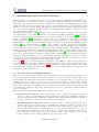
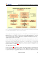
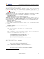
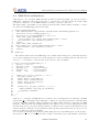
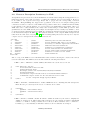
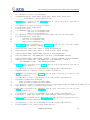
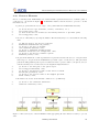
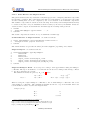
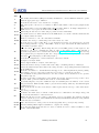
Figure 1: The components of the DD4hep detector geometry toolkit.
1.2
Toolkit Design
Figure 1 shows the architecture of the main components of the toolkit and their interfaces to the
end-user applications, namely the simulation, reconstruction, alignment and visualization. The central
element of the toolkit is the so-called generic detector description model. This is an in-memory model,
i.e., a set of C++ objects holding the data describing the geometry and other information of the
detector. The rest of the toolkit consists of tools and interfaces to input or output information from
this generic detector model. The model and its components will be described in subsequence sections.
1.2.1
The Compact Detector Description
Inspired from the work of the linear collider detector simulation [9, 10], the compact detector description
is used to define an ideal detector as typically used during the conceptual design phase of an experiment.
The compact description in its minimalistic form is probably not going to be adequate later in the
detector life cycle and is likely to be replaced or refined when a more realistic detector with deviations
from the ideal would be needed by the experiment.
In the compact description the detector is parametrized in minimalistic terms with user provided
parameters in XML. XML is an open format, the DD4hep parsers do not validate against a fix schema
DD4hep User Manual
2
Advanced European Infrastructures for Detectors at Accelerators
and hence allow to easily introduce new elements and attributes to describe detectors. This feature
minimizes the burden on the end-user while still supporting flexibility. Such a compact detector
descriptions cannot be interpreted in a general manner, therefore so called Detector Constructors
are needed.
1.2.2
Detector Constructors
Detector Constructors are relatively small code fragments that get as input an XML element from
the compact description that represents a single detector instance. The code interprets the data and
expands its geometry model in memory using the elements from the generic detector description model
described in section 1.3. The toolkit invokes these code fragments in a data driven way using naming
conventions during the initialization phase of the application. Users focus on one single detector type
at the time, but the toolkit supports them to still construct complex and large detector setups. Two
implementations are currently supported: One is based on C++, which performs better and is able to
detect errors at compiler time, but the code is slightly more technical. The other is based on Python
fragments, the code is more readable and compact but errors are only detected at execution time.
The compact description together with the detector constructors are sufficient to build the detector
model and to visualize it. If during the lifetime of the experiment the detector model changes, the
corresponding constructors will need to be adapted accordingly. DD4hep provides already a palette
of basic pre-implemented geometrical detector concepts to design experiments. In view of usage of
DD4hep as a detector description toolkit, this library may in the future also adopt generic designs of
detector components created by end users e.g. during the design phase of future experiments.
1.3
Generic Detector Description Model
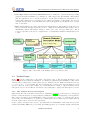
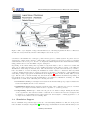
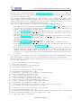
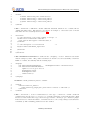
This is the heart of the DD4hep detector description toolkit. Its purpose is to build in memory a
model of the detector including its geometrical aspects as well as structural and functional aspects.
The design reuses the elements from the ROOT geometry package and extends them in case required
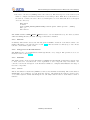
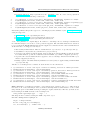
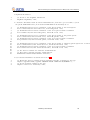
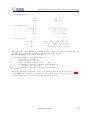
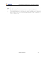
functionality is not available. Figure 2 illustrates the main players and their relationships. Any detector
is modeled as a tree of Detector Elements, the entity central to this design, which is represented in
the implementation by the DetElement class [3]. It offers all applications a natural entry point to
any detector part of the experiment and represents a complete sub-detector (e.g. TPC), a part of a
sub-detector (e.g. TPC-Endcap), a detector module or any other convenient detector device. The main
purpose is to give access to the data associated to the detector device. For example, if the user writes
some TPC reconstruction code, accessing the TPC detector element from this code will provide access
the all TPC geometrical dimensions, the alignment and calibration constants and other slow varying
conditions such as the gas pressure, end-plate temperatures etc. The Detector Element acts as a data
concentrator. Applications may access the full experiment geometry and all connected data through a
singleton object called LCDD, which provides management, bookkeeping and ownership to the model
instances.
The geometry is implemented using the ROOT geometry classes, which are used directly without
unnecessary interfaces to isolate the end-user from the actual ROOT based implementation. There is
one exception: The constructors are wrapped to facilitate a very compact and readable notation to
end-users building custom Detector Constructors.
1.3.1
Detector Element Tree versus the Geometry Hierarchy
The geometry part of the detector description is delegated to the ROOT classes. Logical V olumes
are the basic objects used in building the geometrical hierarchy. A Logical V olume is a shape with
its dimensions and consist of a given material. They represent unpositioned objects which store all
information about the placement of possibly embedded volumes. The same volume can be replicated
several times in the geometry. The Logical V olume also represents a system of reference with respect
to its containing volumes. The reuse of instances of Logical V olumes for different placements optimizes
the memory consumption and detailed geometries for complex setups consisting of millions of volumes
DD4hep User Manual
3
Advanced European Infrastructures for Detectors at Accelerators
Figure 2: Class diagram with the main classes and their relations for the Generic Detector Description
Model. The implementing ROOT classes are shown in brackets.
may be realized with reasonable amount of memory. The difficulty is to identify a given positioned
volume in space and e.g. applying misalignment to one of these volumes. The relationship between
the Detector Element and the placements is not defined by a single reference to the placement, but the
full path from the top of the detector geometry model to resolve existing ambiguities due to the reuse
of Logical V olumes. Hence, individual volumes must be identified by their full path from mother to
daughter starting from the top-level volume.
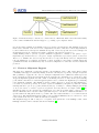
The tree structure of Detector Elements is a parallel structure to the geometrical hierarchy. This
structure will probably not be as deep as the geometrical one since there would not need to associate
detector information at very fine-grain level - it is unlikely that every little metallic screw needs associated detector information such as alignment, conditions, etc. Though this screw and many other
replicas must be described in the geometry description since it may be important e.g. for its material
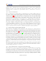
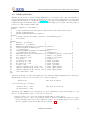
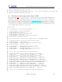
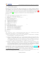
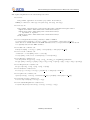
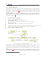
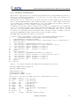
contribution in the simulation application. Thus, the tree of Detector Elements is fully degenerate and
each detector element object will be placed only once in the detector element tree as illustrated for a
hypothetical TPC detector in Figure 3.
1.3.2
Extensions and Views
As depicted in Figure 1 the reconstruction application will require special functionality extending
the basics offered by the common detector element. This functionality may be implemented by a
set of specialized classes that will extend the detector element. These extensions will be in charge of
providing specific answers to the questions formulated by the reconstruction algorithms such as pattern
recognition, tracking, vertexing, particle identification, etc. One example could be to transform a
DD4hep User Manual
4
Advanced European Infrastructures for Detectors at Accelerators
Figure 3: The object diagram of a hypothetical TPC detector showing in parallel the Detector Element
and the Geometry hierarchy and the relationships between the objects.
calorimeter cell identifier into a 3D space position in the global coordinate system. A generic detector
description toolkit would be unable to answer this concrete question, however it provides a convenient
environment for the developer to slot-in code fragments, which implement the additional functionality
using parameters stored in the XML compact description.
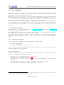
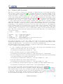
Depending on the functionality these specialized component must be able to either store additional
data, expose additional behavior or both. Additional behavior may easily be added overloading the
DetElement class using its internal data. The internal data is public and addressed by reference,
hence any number of views extending the DetElement behavior may be constructed with very small
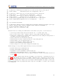
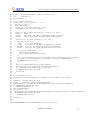
overhead. Additional data may be added by any user at any time to any instance of the DetElement
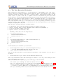
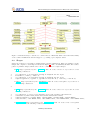
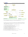
class using a simple aggregation mechanism shown in Figure 4. Data extensions must differ by their
type. The freedom to attach virtually any data item allows for optimized attachments depending on
the application type, such as special attachments for reconstruction, simulation, tracking, etc. This
design allows to build views addressing the following use-cases:
• Convenience Views provide higher level abstractions and internally group complex calculations.
Such views simplify the life of the end-users.
• Optimization Views allows end-users extend the data of the common detector detector element
and store precomputed results, which would be expensive to obtain repeatedly.
• Compatibility Views help to ensure smooth periods of software redesign. During the life-time
of the experiment often various software constructs are for functional reasons re-designed and
re-engineered. Compatibility Views either adapt new data designs to existing application code
or expose new behavior based on existing data.
1.4
Simulation Support
Detector-simulation depends strongly on the use of an underlying simulation toolkit, the most prominent candidate nowadays being Geant4 [8]. DD4hep supports simulation activities with Geant4 providDD4hep User Manual
5
Advanced European Infrastructures for Detectors at Accelerators
Figure 4: Extensions may be attached to common Detector Elements which extend the functionality
of the common DetElement class and support e.g. caching of precomputed values.
ing an automatic translation mechanism between geometry representations. The simulation response
in the active elements of the detector is not implemented by the toolkit, since it is strongly influenced
by the technical choices and precise simulations depends on the very specific detection techniques. In
Geant4 this response is computed in software constructs called Sensitive Detectors.
Ideally DD4hep aims to provide a generic simulation application. Similar to the palette of preimplemented geometrical detector concepts to design experiments, it provides a palette of Sensitive
Detectors to simulate the detector response in form of a component library. Detector designers may
base the simulation of a planned experiment on these predefined components for initial design and
optimization studies. In a similar way easy access and configuration of other user actions of Geant4 is
provided.
1.5
Detector Alignment Support
The support for alignment operations is crucial to the usefulness of the toolkit. In the linear collider
community this support is basically missing in all the currently used geometry description systems.
The possibility to apply into the detector description alignment deltas (differences with respect the
ideal or measured position) and read them from an external source is mandatory to exploit the toolkit.
A typical alignment application would consist of calculating a new set of deltas from a given starting
point, which could then be loaded and applied again in order to validate the alignment by recalculating
some alignment residuals. The ROOT geometry package supports to apply an [mis]-alignment to
touchable objects in the geometry. T ouchable objects are identified by the path of positioned volumes
starting with the top node (e.g. path=/T OP/A1 /B4 /C3 ). Contrary to ordinary multiple placements
of Logical V olumes, touchable objects are degenerate and only valid for one single volume [6]. To
simplify the usage for the end user, the identification of a positioned volume will be connected to the
Detector Element, where only the relative path with respect to the Detector Element will have to be
specified rather the full path from the top volume. The delta-values will have to be read from various
data sources. The initial implementation will be based on simple XML files, later a connection to other
sources such as the detector conditions database is envisaged.
The alignment support will be subject to a separate development line of the DD4hep toolkit, called
DDAlign and hence will be discussed in another manual [12].
DD4hep User Manual
6
Advanced European Infrastructures for Detectors at Accelerators
2
User Manual
This chapter describes how supply a physics application developed with all the information related to
the detector which is necessary to process data from particle collisions and to qualify the detecting
apparatus in order to interpret these event data.
The clients of the detector description are the algorithms residing in the event processing framework
that need this information in order to perform their job (reconstruction, simulation, etc.). The detector description provided by DD4hep is a framework for developers to provide the specific detector
information to software algorithms, which process data from particle collisions.
In the following sections an overview is given over the various independent elements of DD4hep followed
by the discussion of an example which leads to the description of a detector when combining these
elements. This includes a discussion of the features of the DD4hep detector description and of its
structure.
2.1
Building DD4hep
The DD4hep source code is freely available. See the licence conditions . Please read the Release Notes
before downloading or using this release.
The DD4hep project consists of several packages. The idea has been to separate the common parts of
the detector description toolkit from concrete detector examples.
The package DDCore contains the definition of the basic classes of the toolkit: Handle, DetElement,
Volume, PlacedVolume, Shapes, Material, etc. Most of these classes are handles to ROOT’s TGeom
classes.
2.1.1
Supported Platforms
Supported platforms for DD4hep are the CERN Linux operating systems:
• Scientic Linux CERN 6
• Scientic Linux CERN 7 - once approved.
Support for any other platform will well be taken into account, but can only be actively supported by
users who submit the necessary patches.
2.1.2
Prerequisites
DD4hep depends on a number of external packages. The user will need to install these in his/her
system before building and running the examples
• Mandatory are recent CMake (version 2.8 or higher) and
• ROOT (version 5.34 or higher) installations. 1
• If the Xerces − C is used to parse compact descriptions and installation of Xerces-C will be
required.
• To build DDG4 it is mandatory to have an installation of the Boost header files.
• To build and run the simulation examples Geant4 will be required.
1 Please not, that due to the removal of the Reflex plugin mechanism from ROOT 6, version 6 of ROOT is currently
not supported. This deficiency will be waved in the future.
DD4hep User Manual
7
Advanced European Infrastructures for Detectors at Accelerators
2.1.3
CMake Build Options for DD4hep
The package provides the basic mechanisms for constructing the Generic Detector Description Model
in memory from XML compact detector definition files. Two methods are currently supported: one
based on the C++ Xerces-C parser, and another one based on Python and using the PyROOT bindings
to ROOT 2 . PyROOT may be enabled using the switch:
-DD4HEP_USE_PYROOT:BOOL
The XML parsing method is enabled by default using the TiXML parser. Optionally instead of TiXML
the Xerces-C parser may be chosen by setting the two configuration options appropriately:
-DD4HEP_USE_XERCESC:BOOL
-DXERCESC_ROOT_DIR=<path to Xerces-C-installation-directory>
DDG4 is the package that contains the conversion of DD4hep geometry into Geant4 geometry to be
used for simulation. The option DD4HEP WITH GEANT4 : BOOL controls the building or not of this package
that has the dependency to Geant4. The Geant4 installation needs to be located using the variable:
-DDD4HEP_WITH_GEANT4=on -D
-DGeant4_DIR=<path to Geant4Config.cmake>
To properly handle component properties using boost :: spirit, access to the Boost header files must
be provided.
-DDD4HEP_USE_BOOST=ON
-DBOOST_INCLUDE_DIR=<path to the boost include directory>
Other useful build options:
• build doxygen documentation ( after ’install’ open ./doc/html/index.html)
-D INSTALL_DOC=on
• note: you might have to update your environment beforehand to have all needed libraries in the
shared lib search path (this will vary with OS, shell, etc.) e.g
. /data/ilcsoft/geant4/9.5/bin/geant4.sh
export CLHEP_BASE_DIR="/data/ilcsoft/HEAD/CLHEP/2.1.0.1"
export CLHEP_INCLUDE_DIR="$CLHEP_BASE_DIR/include"
export PATH="$CLHEP_BASE_DIR/bin:$PATH"
export LD_LIBRARY_PATH="$CLHEP_BASE_DIR/lib:$LD_LIBRARY_PATH"
2.1.4
Build From Source
The following steps are necessary to build DD4hep :
• Set the environment, at least ROOT needs to be initialized, e.g.
source
/data/ilcsoft/root/5.34.03/bin/thisroot.sh
(the bare minimum is: exportROOTSYS =< pathtorootinstallation >).
• First checkout code from the repository:
svn co https://svnsrv.desy.de/public/aidasoft/DD4hep/trunk DD4hep
2 I will not continue the support using PyROOT.
If there is a desire that it stays alive someone else should take care – M.Frank
DD4hep User Manual
8
Advanced European Infrastructures for Detectors at Accelerators
• We refer to the directory DD4hep as the source directory. The next step is to create a directory in
which to configure and run the build and store the build products. This directory should not be
the same as, or inside, the source directory. In this guide, we create this build directory alongside
our source directory:
mkdir build
cd build
cmake -DCMAKE_INSTALL_PREFIX=<dd4hep-install-pasth> <CMake-options> ../DD4hep
make -j 4
make install
The CMake Variable CMAKE INSTALL PREFIX is used to set the install directory, the directory under
which the DD4hep libraries, headers and support files will be installed.
2.1.5
Tutorial
In January 2013 an introductory tutorial was given at CERN to members of the linear collider community. The slides to the tutorial can be found here . The tutorial is not entirely up to date. Please
take the content with a grain of salt.
2.1.6
Doxygen Code Documentation
The DD4hep source code is instrumented with tags understood by doxygen. The generated code documentation can be found here .
2.1.7
Remarks
The main reference is the doxygen information of DD4hep and the ROOT documentation. Please refer
to these sources for a detailed view of the capabilities of each component and/or its handle. For
coherence reasons, the description of the interfaces is limited to examples which illustrate the usage of
the basic components.
2.1.8
Caveat
The atomic units in of Geant4 are (millimeter, nanosecond and MeV and radians). The atomic units of
ROOT-TGeo are (centimeter, seconds, GeV and degrees). Unfortunately the authors could not agree
on a common system of units and mixing the two can easily result in a chaos. Users must be aware of
this fact.
DD4hep User Manual
9
Advanced European Infrastructures for Detectors at Accelerators
2.2
DD4hep Handles
Handles are the means of clients accessing DD4hep detector description data. The data itself is not
held by the handle itself, the handle only allows the access to the data typically held by a pointer. The
template handle class (see for details the header file ). allows type safe assignment of other unrelated
handles and supports standard data conversions to the underlying object in form of the raw pointer, a
reference etc. The template handle class:
1 template <typename T> class Handle {
2 public:
3
// Type definitions and class specific abbreviations and forward declarations
4
typedef T Implementation;
5
typedef Handle<Implementation> handle_t;
6 public:
7
// Single and only data member: pointer to the underlying object
8
T* m_element;
9
10 public:
11
Handle() : m_element(0)
{
}
12
Handle(T* e) : m_element(e)
{
}
13
Handle(const Handle<T>& e) : m_element(e.m_element) {
}
14
template<typename Q> Handle(Q* e)
15
: m_element((T*)e)
{ verifyObject();
}
16
template<typename Q> Handle(const Handle<Q>& e)
17
: m_element((T*)e.m_element)
{ verifyObject();
}
18
Handle<T>& operator=(const Handle<T>& e) { m_element=e.m_element; return *this;}
19
bool isValid() const
{ return 0 != m_element;
}
20
bool operator!() const
{ return 0 == m_element;
}
21
void clear()
{ m_element = 0;
}
22
T* operator->() const
{ return m_element;
}
23
operator T& () const
{ return *m_element;
}
24
T& operator*() const
{ return *m_element;
}
25
T* ptr() const
{ return m_element;
}
26
template <typename Q> Q* _ptr() const
{ return (Q*)m_element;
}
27
template <typename Q> Q* data() const
{ return (Q*)m_element;
}
28
template <typename Q> Q& object() const { return *(Q*)m_element;
}
29
const char* name() const;
30 };
effectively works like a pointer with additional object validation during assignment and construction.
Handles support direct access to the held object: either by using the
operator->()
(See line 16 above)
or the automatic type conversions:
operator T& ()
T& operator*()
const
const.
(See line 17-18 above)
All entities of the DD4hep detector description are exposed as handles - raw pointers should not occur
in the code. The handles to these objects serve two purposes:
• Hold a pointer to the object and extend the functionality of a raw pointer.
• Enable the creation of new objects using specialized constructors within sub-classes. To ensure
memory integrity and avoid resource leaks these created objects should always be stored in the
detector description data hub LCDD described in section 2.5.
DD4hep User Manual
10
Advanced European Infrastructures for Detectors at Accelerators
2.3
The Data Extension Mechanism
Data extensions are client defined C++ objects aggregated to basic DD4hep objects. The need to
introduce such data extensions results from the simple fact that no data structure can be defined
without the iterative need in the long term to extend it leading to implementations, which can only
satisfy a subset of possible clients. To accomplish for this fact a mechanism was put in place which
allows any user to attach any supplementary information provided the information is embedded in a
polymorph object with an accessible destructor. There is one limitation though: object extension must
differ by their interface type. There may not be two objects attached with the identical interface type.
The actual implemented sub-type of the extension is not relevant. Separating the interface type from
the implementation type keeps client code still functional even if the implementation of the extension
changes or is a plug-able component.
The following code snippet shows the extension interface:
1
2
3
4
/// Extend the object with an arbitrary structure accessible by the type
template <typename IFACE, typename CONCRETE> IFACE* addExtension(CONCRETE* c);
/// Access extension element by the type
template <class T> T* extension() const;
Assuming a client class of the following structure:
1
2
3
4
5
6
7
8
9
10
class ExtensionInterface {
virtual ~ExtensionInterface();
virtual void foo() = 0;
};
class ExtensionImplementation : public ExtensionInterface {
ExtensionImplementation();
virtual ~ExtensionImplementation();
virtual void foo();
};
is then attached to an extensible object as follows:
1
2
3
ExtensionImplementation* ptr = new ExtensionImplementation();
... fill the ExtensionImplementation instance with data ...
module.addExtension<ExtensionInterface>(ptr);
The data extension may then be retrieved whenever the instance of the extensible object ”module” is
accessible:
1
ExtensionInterface* ptr = module.extension<ExtensionInterface>();
The lookup mechanism is rather efficient. Though it is advisable to cache the pointer withing the client
code if the usage is very frequent.
There are currently three object types present which support this mechanism:
• the central object of DD4hep , the LCDD class discussed in section 2.5.
• the object describing subdetectors or parts thereof, the DetElement class discussed in section 2.10.
Detector element extensions in addition require the presence of a copy constructor to support
e.g. reflection operations. Without a copy mechanism detector element hierarchies could cloned.
• the object describing sensitive detectors, the SensitiveDetector class discussed in section 2.11.
DD4hep User Manual
11
Advanced European Infrastructures for Detectors at Accelerators
2.4
XML Tools and Interfaces
Using native tools to interpret XML structures is rather tedious and lengthy. To easy the access to
XML data considerable effort was put in place to easy the life of clients as much as possible using
predefined constructs to access XML attributes, elements or element collections.
The functionality of the XML tools is perhaps best shown with a small example. Imagine to extract
the data from an XML snippet like the following:
1
2
3
4
5
6
7
8
9
10
11
12
13
14
<detector name="Sometthing">
<tubs rmin="BP_radius - BP_thickness" rmax="BP_radius" zhalf="Endcap_zmax/2.0"/>
<position x="0" y="0" z="Endcap_zmax/2.0" />
<rotation x="0.0" y="CrossingAngle/2.0" z="0.0" />
<layer id="1" inner_r="Barrel_r1"
outer_r="Barrel_r1 + 0.02*cm" inner_z="Barrel_zmax + 0.1*cm">
<slice material = "G10" thickness ="0.5*cm"/>
</layer>
<layer id="2" inner_r="Barrel_r2"
outer_r="Barrel_r2 + 0.02*cm" inner_z="Barrel_zmax + 0.1*cm">
<slice material = "G10" thickness ="0.5*cm"/>
</layer>
....
</detector>
The variable names used in the XML snippet are evaluated when interpreted. Unless the attributes
are accessed as strings, the client never sees the strings, but only the evaluated numbers. The anatomy
of the C++ code snippets to interpret such a data section looks very similar:
1
2
3
4
5
6
7
8
9
10
11
12
13
14
15
16
17
18
19
20
static void some_xml_handler(xml_h e) {
xml_det_t x_det (e);
xml_comp_t x_tube
= x_det.tubs();
xml_dim_t pos
= x_det.position();
xml_dim_t rot
= x_det.rotation();
string
name
= x_det.nameStr();
for(xml_coll_t i(x_det,_U(layer)); i; ++i)
xml_comp_t x_layer = i;
double zmin = x_layer.inner_z();
double rmin = x_layer.inner_r();
double rmax = x_layer.outer_r();
double layerWidh = 0;
{
for(xml_coll_t j(x_layer,_U(slice)); j; ++j) {
double thickness = xml_comp_t(j).thickness();
layerWidth += thickness;
}
}
}
In the above code snippet an XML (sub-)tree is passed to the executing function as a handle to an XML
element (xml h). Such handles may seamlessly be assigned to any supporting helper class inheriting
from the class XML::Element, which encapsulates the functionality required to interpret the XML
structures. Effectively the various XML attributes and child nodes are accessed using functions with
the same name from a convenience handle. In lines 3-5 child nodes are extracted, lines 10-12,16 access
element attributes. Element collections with the same tag names layer and slice are exposed to the
client code using an iteration mechanism.
Note the macros U(layer) and U(slice): When using Xerces-C as an XML parser, it will expand to
the reference to an object containing the unicode value of the string ”layer”. The full list of predefined
DD4hep User Manual
12
Advanced European Infrastructures for Detectors at Accelerators
tag names can be found in the include file DD4hep/UnicodeValues.h . If a user tag is not part in the
precompiled tag list, the corresponding Unicode string may be created with the macro Unicode(layer)
or the function Unicode(”layer”).
The convenience handles actually implement these functions to ease life. There is no magic - newly
created attributes with new names obviously cannot be accessed with convenience mechanism. Hence,
either you know what you are doing and you create your own convenience handlers or you restrict
yourself a bit in the creativity of defining new attribute names.
There exist several utility classes to extract data from predefined XML tags:
• Any XML element is described by an XML handle XML::Handle t (xml t). Handles are the
basic structure for the support of higher level interfaces described above. The assignment of a
handle to any of the interfaces below is possible.
• The class XML::Element (xml elt t) supports in a simple way the navigation through the
hierarchy of the XML tree accessing child nodes and attributes. Attributes at this level are
named entities and the tag name must be supplied.
• The class XML::Dimension with the type definition xml dim t, supports numerous access functions named identical to the XML attribute names. Such helper classes simplify the tedious string
handling required by the
• The class XML::Component (xml comp t) and
the class XML::Detector (xml det t) resolving other issues useful to construct detectors.
• Sequences of XML elements with an identical tag name may be handled as iterations as shown
in the Figure above using the class XML::Collection t .
• Convenience classes, which allow easy access to element attributes may easily be constructed
using the methods of the XML::Element class. This allows to construct very flexible thou nonintrusive extensions to DD4hep . Hence there is a priori no need to modify these helpers for the
benefit of only one single client. In the presence of multiple requests such extensions may though
be adopted.
It is clearly the responsibility of the client to only request attributes from an XML element, which
exist. If an attribute, a child node etc. is not found within the element an exception is thrown.
The basic interface of the XML :: Element class allows to access tags and child nodes not exposed by
the convenience wrappers:
1
2
3
4
5
6
7
8
9
10
11
12
13
14
15
16
17
18
19
20
21
22
23
/// Access the tag name of this DOM element
std::string tag() const;
/// Access the tag name of this DOM element
const XmlChar* tagName() const;
/// Check for the existence of a named attribute
bool hasAttr(const XmlChar* name) const;
/// Retrieve a collection of all attributes of this DOM element
std::vector<Attribute> attributes() const;
/// Access single attribute by it’s name
Attribute getAttr(const XmlChar* name) const;
/// Access attribute with implicit return type conversion
template <class T> T attr(const XmlChar* tag) const;
/// Access attribute name (throws exception if not present)
const XmlChar* attr_name(const Attribute attr) const;
/// Access attribute value by the attribute (throws exception if not present)
const XmlChar* attr_value(const Attribute attr) const;
/// Check the existence of a child with a given tag name
bool hasChild(const XmlChar* tag) const;
/// Access child by tag name. Thow an exception if required in case the child is not present
Handle_t child(const Strng_t& tag, bool except = true) const;
/// Add a new child to the DOM node
DD4hep User Manual
13
Advanced European Infrastructures for Detectors at Accelerators
24
25
26
Handle_t addChild(const XmlChar* tag) const;
/// Check if a child with the required tag exists - if not create it and add it to the current node
Handle_t setChild(const XmlChar* tag) const;
2.5
The Detector Description Data Hub: LCDD
As shown in Figure 2, any access to the detector description data is done using a standardized interface
called LCDD. During the configuration phase of the detector the interface is used to populate the
internal data structures. Data structures present in the memory layout of the detector description
may be retrieved by clients at any time using the LCDD interface class . This includes of course, the
access during the actual detector construction. The following code listing shows the accessor method
to retrieve detector description entities from the interface. Not shown are access methods for groups
of these entities and the methods to add objects:
1 struct LCDD {
2
3 ///+++ Shortcuts to access often used quantities
4
5 /// Return handle to material describing air
6 virtual Material air() const = 0;
7 /// Return handle to material describing vacuum
8 virtual Material vacuum() const = 0;
9 /// Return handle to "invisible" visualization attributes
10 virtual VisAttr invisible() const = 0;
11
12 ///+++ Access to the top level detector elements and the corresponding volumes
13
14 /// Return reference to the top-most (world) detector element
15 virtual DetElement
world() const = 0;
16 /// Return reference to detector element with all tracker devices.
17 virtual DetElement
trackers() const = 0;
18
19 /// Return handle to the world volume containing everything
20 virtual Volume
worldVolume() const = 0;
21 /// Return handle to the volume containing the tracking devices
22 virtual Volume
trackingVolume() const = 0;
23
24 ///+++ Access to geometry and detector description objects
25
26 /// Retrieve a constant by it’s name from the detector description
27 virtual Constant
constant(const std::string& name)
const = 0;
28 /// Retrieve a matrial by it’s name from the detector description
29 virtual Material
material(const std::string& name)
const = 0;
30 /// Retrieve a field component by it’s name from the detector description
31 virtual DetElement
detector(const std::string& name)
const = 0;
32 /// Retrieve a sensitive detector by it’s name from the detector description
33 virtual SensitiveDetector sensitiveDetector(const std::string& name) const = 0;
34 /// Retrieve a readout object by it’s name from the detector description
35 virtual Readout
readout(const std::string& name)
const = 0;
36 /// Retrieve a id descriptor by it’s name from the detector description
37 virtual IDDescriptor idSpecification(const std::string& name)
const = 0;
38 /// Retrieve a subdetector element by it’s name from the detector description
39 virtual CartesianFieldfield(const std::string& name)
const = 0;
40
41 ///+++ Access to visualisation attributes and Geant4 processing hints
42
DD4hep User Manual
14
Advanced European Infrastructures for Detectors at Accelerators
43 /// Retrieve a visualization attribute by it’s name from the detector description
44 virtual VisAttr
visAttributes(const std::string& name) const = 0;
45
46 /// Retrieve a region object by it’s name from the detector description
47 virtual Region
region(const std::string& name)
const = 0;
48 /// Retrieve a limitset by it’s name from the detector description
49 virtual LimitSet
limitSet(const std::string& name)
const = 0;
50 /// Retrieve an alignment entry by it’s name from the detector description
51 virtual AlignmentEntryalignment(const std::string& path)
const = 0;
52 ...
53
54 ///+++ Extension mechanism:
55
56 /// Extend the sensitive detector element with an arbitrary structure accessible by the type
57 template <typename IFACE, typename CONCRETE> IFACE* addExtension(CONCRETE* c);
58 /// Access extension element by the type
59 template <class T> T* extension() const;
60 };
As shown in the above listing, the LCDD interface is the main access point to access a whole set
• often used predefined values such as the material ”air” or ”vacuum” (line 5-10).
• the top level objects ”world”, ”trackers” and the corresponding volumes (line 14-22).
• items in the constants table containing named definitions also used during the interpretation of
the XML content after parsing (line 27)
• named items in the the material table (line 29)
• named subdetectors after construction and the corresponding (line 31)
• named sensitive detectors with their (line 33)
• named readout structure definition using a (line 35)
• named readout identifier descriptions (line 37)
• named descriptors of electric and/or magnetic fields (line 39).
Additional support for specialized applications is provided by the interface:
•
•
•
•
•
Geant4: named region settings (line 47)
Geant4: named limits settings (line 49)
Visualization: named visualization attributes (line 44)
Alignment: named alignment entries to correct displaced volumes (line 51)
User defined extensions (line 56-59) are supported with the extension mechanism described in
section 2.3.
All the values are populated either directly from XML or from detector − constructors (see section 1.2.2). The interface also allows to load XML configuration files of any kind provided an appropriate interpretation plugin is present. In the next section we describe the functionality of the ”lccdd”
plugin used to interpret the compact detector description. This mechanism can easily be extended using ROOT plugins, where the plugin name must corrspond to the XML root element of the document
to be interpreted.
DD4hep User Manual
15
Advanced European Infrastructures for Detectors at Accelerators
2.6
Detector Description Persistency in XML
As explained in a previous section, the mechanism involved in the data loading allow an application to be
fairly independent of the technology used to populate the transient detector representation. However,
if one wants to use a given tech- nology, she/he has to get/provide the corresponding conversion
mechanism. Though DD4hep also supports the population of the detector description using python
constructs, we want to focus here on the XML based population. The choice of XML was driven mainly
by its easiness of use and the number of tools provided for its manipulation and parsing. Moreover,
XML data can be easily translated into many other format using tools like XSLT processors. The
grammar used for the XML data is pretty simple and straight forward, actually very similar to other
geometry description languages based on XML. For example the material description is nearly identical
to the material description in GDML [11]. The syntactic structure of the compact XML description was
taken from the SiD detector description [9]. The following listing shows the basic layout of any the
compact detector description file with its different sections:
1 <lccdd>
2
<info>
3
<includes>
4
<define>
5
<materials>
6
<display>
7
<detectors>
8
<readouts>
9
<limits>
10
<fields>
11 </lccdd>
...
...
...
...
...
...
...
...
...
</info>
</includes>
</define>
</materials>
</display>
</detectors>
</readouts>
</limits>
</fields>
Auxiliary detector model information
Section defining GDML files to be included
Dictionary of constant expressions and varables
Additional material definitions
Definition of visualization attributes
Section with sub-detector definitions
Section with readout structure definitions
Definition of limit sets for Geant4
Field definitions
The root tag of the XML tree is lccdd. This name is fixed. In the following the content of the various
sections is discussed. The XML sections are filled with the following information:
• The < info > sub-tree contains auxiliary information about the detector model:
1
2
3
4
5
6
7
8
9
<info name="clic_sid_cdr"
title="CLIC Silicon Detector CDR"
author="Christian Grefe"
url="https://twiki.cern.ch/twiki/bin/view/CLIC/ClicSidCdr"
status="development"
version="$Id: compact.xml 665 2013-07-02 18:49:26Z markus.frank $">
<comment>The compact format for the CLIC Silicon Detector used
for the conceptual design report</comment>
</info>
• The < includes > section allows to include GDML sub-trees containing material descriptions.
These files are processed before the detector constructors are called:
1
2
3
4
5
<includes>
<gdmlFile
<gdmlFile
...
</includes>
ref="elements.xml"/>
ref="materials.xml"/>
• The < define > section contains all variable definitions defined by the client to simplify the
definition of subdetectors. These name-value pairs are fed to the expression evaluator and MUST
evaluate to a number. String constants are not allowed. These variables can be combined to
formulas e.g. to automatically re-dimension subdetectors if boundaries are changed:
DD4hep User Manual
16
Advanced European Infrastructures for Detectors at Accelerators
1
2
3
4
5
6
7
<define>
<constant
<constant
<constant
<constant
....
</define>
name="world_side" value="30000"/>
name="world_x" value="world_side"/>
name="world_y" value="world_side"/>
name="world_z" value="world_side"/>
• The < materials > sub-tree contains additional materials, which are not contained in the
default materials tables. The snippet below shows an example to extend the table of known
materials. For more details please see section 2.7.
1
2
3
4
5
6
7
8
9
10
11
12
<materials>
<!-- The description of an atomic element or isotope -->
<element Z="30" formula="Zn" name="Zn" >
<atom type="A" unit="g/mol" value="65.3955" />
</element>
...
<!-- The description of a new material
-->
<material name="CarbonFiber_15percent">
...
</material>
...
</materials>
• The visualization attributes are defined in the < display > section. Clients access visualization settings by name. The possible attributes are shown below and essentially contain the
RGB color values, the visibility and the drawing style:
1
2
3
4
5
6
7
8
9
<display>
<vis name="InvisibleNoDaughters"
<vis name="SiVertexBarrelModuleVis"
alpha="1.0" r="1" g="1" b="0.6"
drawingStyle="solid"
showDaughters="true"
visible="true"/>
....
</display>
showDaughters="false" visible="false"/>
• Limisets contain parameters passed to Geant4:
1
2
3
4
5
<limits>
<limitset name="cal_limits">
<limit name="step_length_max" particles="*" value="5.0" unit="mm" />
</limitset>
</limits>
• The < detectors > section contains subtrees of the type < detector > which contain all
parameters used by the detectorconstructors to actually expand the geometrical structure. Each
subdetector has a name and a type, where the type is used to call the proper constructor plugin.
If the subdetector element is sensitive, a forward reference to the corresponding readout structure
is mandatory. The remaining parameters are user defined:
DD4hep User Manual
17
Advanced European Infrastructures for Detectors at Accelerators
1
2
3
4
5
6
7
8
9
10
11
12
13
14
15
16
17
18
<detectors>
<detector id="4" name="SiTrackerEndcap" type="SiTrackerEndcap" readout="SiTrackerEndcapHits">
<comment>Outer Tracker Endcaps</comment>
<module name="Module1" vis="SiTrackerEndcapModuleVis">
<trd x1="36.112" x2="46.635" z="100.114/2" />
<module_component thickness="0.00052*cm"
material="Copper" />
<module_component thickness="0.03*cm"
material="Silicon" sensitive="true" />
...
</module>
...
<layer id="1">
<ring r="256.716" zstart="787.105+1.75" nmodules="24" dz="1.75" module="Module1"/>
<ring r="353.991" zstart="778.776+1.75" nmodules="32" dz="1.75" module="Module1"/>
<ring r="449.180" zstart="770.544+1.75" nmodules="40" dz="1.75" module="Module1"/>
</layer>
...
</detector>
</detectors>
• The < readouts > section defined the encoding of sensitive volumes to so-called cell-ids, which
are in DD4hep 64-bit integer numbers. The encoding is subdetector dependent with one exception:
to uniquely identity each subdetector, the width of the system field must be the same. The usage
of these data is discussed in section ??.
1
2
3
4
5
6
<readouts>
<readout name="SiTrackerEndcapHits">
<id>system:8,barrel:3,layer:4,module:14,sensor:2,side:32:-2,strip:20</id>
</readout>
...
</readouts>
• Electromagnetic fields are described in the < fields > section. There may be several fields
present. In DD4hep the resulting field vectors may be both electric and magnetic. The strength
of the overall field is calculated as the superposition of the individual components:
1
2
3
4
5
6
7
8
9
<fields>
<field name="GlobalSolenoid" type="solenoid"
inner_field="5.0*tesla"
outer_field="-1.5*tesla"
zmax="SolenoidCoilOuterZ"
outer_radius="SolenoidalFieldRadius">
</field>
...
</fields>
DD4hep User Manual
18
Advanced European Infrastructures for Detectors at Accelerators
2.7
Material Description
Materials are needed by logical volumes. They are defined as isotopes, elements or mixtures. Elements
can optionally be composed of isotopes. Composition is always done by specifying the fraction of the
mass. Mixtures can be composed of elements or other mixtures. For a mixture the user can specify
composition either by number of atoms or by fraction of mass. The materials sub-tree in section 2.6
shows the representation of an element, a simple material and a composite material in the XML format
identical to GDML [11]. The snippet below shows how to define new material instances:
1 <materials>
2 ...
3 <!-- (1) The description of an atomic element or isotope -->
4 <element Z="30" formula="Zn" name="Zn" >
5
<atom type="A" unit="g/mol" value="65.3955" />
6 </element>
7 <!-- (2) A composite material
-->
8 <material name="Kapton">
9
<D value="1.43" unit="g/cm3" />
10
<composite n="22" ref="C"/>
11
<composite n="10" ref="H" />
12
<composite n="2" ref="N" />
13
<composite n="5" ref="O" />
14 </material>
15 <!-- (3) A material mixture
-->
16 <material name="PyrexGlass">
17
<D type="density" value="2.23" unit="g/cm3"/>
18
<fraction n="0.806" ref="SiliconOxide"/>
19
<fraction n="0.130" ref="BoronOxide"/>
20
<fraction n="0.040" ref="SodiumOxide"/>
21
<fraction n="0.023" ref="AluminumOxide"/>
22 </material>
23 ...
24 </materials>
The < materials > sub-tree contains additional materials, which are not contained in the default
materials tables. The snippet above shows different kinds of materials:
(1) Atomic elements as they are in the periodic table. The number of elements is finite. It is unlikely
any client will have to extend the known elements.
(2) Composite materials, which consists of one or several elements forming a molecule. These materials have a certain density under normal conditions described in the child element D. For each
composite the attribute ref denotes the element type by name, the attribute n denotes the
atomic multiplicity. Typically each of the elements in (1) also forms such a material representing
objects which consist of pure material like e.g. iron magnet yokes or copper wires.
(3) Last there are mixtures of composite materials to describe for example alloys, solutions or other
mixtures of solid materials. This is the type of material used to actually create mechanical
structures forming the assembly of an experiment. Depending on the maufactering these materials
have a certain density (D) and are composed of numerous molecules contributing to the resulting
material with a given fraction. The sum of all fractions (attribute n) is 1.0.
”Real” materials i.e. those you can actually touch are described in TGeo by the class TGeoMedium 3 .
Materials are not constructed by any client. Materials and elements are either already present in the
the corresponding tables of the ROOT geometry package or they are added during the interpretation
of the XML input. Clients access the description of material using the LCDD interface.
3 Typical beginner’s mistake: Do not mix up the two classes TGeoMaterial and TGeoMedium! The material to define
volumes is of type TGeoMedium, which also includes the description of the material’s finish.
DD4hep User Manual
19
Advanced European Infrastructures for Detectors at Accelerators
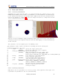
Figure 5: Extensions may be attached to common Detector Elements which extend the functionality
of the common DetElement class and support e.g. caching of precomputed values.
2.8
Shapes
Shapes are abstract objects with a bounding surface and fixed dimensions. There are primitive, atomic
shapes and complex boolean shapes as shown in Figure 5. TGeo and similarly Geant4 offer a whole
palette of primitive shapes, which can be used to construct more complex shapes:
• Box shape represented by the TGeoBBox class. To create a new box object call one of the
following constructors:
1
2
3
4
/// Constructor to be used when creating an anonymous new box object
Box(double x, double y, double z);
/// Constructor to be used when creating an anonymous new box object
template<typename X, typename Y, typename Z> Box(const X& x, const Y& y, const Z& z);
• Sphere shape represented by the TGeoSphere class. To create a new sphere object call one of
the following constructors:
1
• Cone shape represented by the TGeoCone class. To create a new cone object call one of the
following constructors:
1
2
3
4
/// Constructor to create a new anonymous object with attribute initialization
Cone(double z,double rmin1,double rmax1,double rmin2,double rmax2);
template<typename Z, typename RMIN1, typename RMAX1, typename RMIN2, typename RMAX2>
Cone(const Z& z, const RMIN1& rmin1, const RMAX1& rmax1, const RMIN2& rmin2, const RMAX2& rmax2);
• Cone segment shape represented by the TGeoConeSeg class. To create a new cone segment
object call one of the following constructors:
DD4hep User Manual
20
Advanced European Infrastructures for Detectors at Accelerators
1
2
3
/// Constructor to create a new ConeSegment
ConeSegment(double dz, double rmin1, double rmax1, double rmin2, double rmax2,
double phi1=0.0, double phi2=2.0*M_PI);
• Polycone shape represented by the TGeoPcon class. To create a new polycone object call one
of the following constructors:
1
2
3
4
5
6
7
8
9
10
11
/// Constructor to create a new polycone object
Polycone(double start, double delta);
followed by a call to:
void addZPlanes(const std::vector<double>& rmin,
const std::vector<double>& rmax,
const std::vector<double>& z);
/// Constructor to create a new polycone object. Add at the same time all Z planes
Polycone(double start, double delta,
const std::vector<double>& rmin,
const std::vector<double>& rmax,
const std::vector<double>& z);
• Tube segment shape represented by the TGeoTubeSeg class. To create a new tube segment
object call one of the following constructors:
1
2
3
4
5
6
7
8
9
Tube(double rmin, double rmax, double z, double deltaPhi=2*M_PI)
Tube(double rmin, double rmax, double z, double startPhi, double deltaPhi)
template<typename RMIN, typename RMAX, typename Z, typename DELTAPHI>
Tube(const RMIN& rmin, const RMAX& rmax, const Z& z, const DELTAPHI& deltaPhi)
template<typename RMIN, typename RMAX, typename Z, typename STARTPHI, typename DELTAPHI>
Tube(const std::string& name, const RMIN& rmin, const RMAX& rmax, const Z& z,
const STARTPHI& startPhi, const DELTAPHI& deltaPhi)
• Trapezoid shape represented by the TGeoTrd class. To create a new trapezoid object call one
of the following constructors:
1
2
/// Constructor to create a new anonymous object with attribute initialization
Trapezoid(double x1, double x2, double y1, double y2, double z);
• Trap shape represented by the TGeoTrap class. To create a new trap object call one of the
following constructors:
1
2
3
4
5
6
/// Constructor to create a new anonymous object with attribute initialization
Trap(double z,double theta,double phi,
double y1,double x1,double x2,double alpha1,
double y2,double x3,double x4,double alpha2);
/// Constructor to create a new anonymous object for right angular wedge from STEP (Se G4 manual for deta
Trap( double pz, double py, double px, double pLTX);
• Torus shape represented by the TGeoTorus class. To create a new torus object call one of the
following constructors:
1
2
/// Constructor to create a new anonymous object with attribute initialization
Torus(double r, double rmin, double rmax, double phi=M_PI, double delta_phi=2.*M_PI);
• Paraboloid shape represented by the TGeoParaboloid class. To create a new paraboloid object
call one of the following constructors:
1
2
/// Constructor to create a new anonymous object with attribute initialization
Paraboloid(double r_low, double r_high, double delta_z);
DD4hep User Manual
21
Advanced European Infrastructures for Detectors at Accelerators
• Regular Polyhedron shape represented by the TGeoPgon class. To create a new polyhedron
object call one of the following constructors:
1
2
3
4
5
6
/// Constructor to create a new object. Phi(start)=0, deltaPhi=2PI, Z-planes at +-zlen/2
PolyhedraRegular(int nsides, double rmin, double rmax, double zlen);
/// Constructor to create a new object. Phi(start)=0, deltaPhi=2PI, Z-planes at zplanes[0],[1]
PolyhedraRegular(int nsides, double rmin, double rmax, double zplanes[2]);
/// Constructor to create a new object with phi_start, deltaPhi=2PI, Z-planes at +-zlen/2
PolyhedraRegular(int nsides, double phi_start, double rmin, double rmax, double zlen);
Besides the primitive shapes three types of boolean shapes (described in TGeo by the TGeoCompositeShape
class) are supported:
• UnionSolid objects representing the union,
• IntersectionSolid objects representing the intersection,
• SubtractionSolid objects representing the subtraction,
of two other primitive or complex shapes. To build a boolean shape, the second shape is transformed
in 3-dimensional space before the boolean operation is applied. The 3D transformations are described
by objects from the ROOT::Math library and are supplied at construction time. Such a transformation
as shown in the code snippet below may be
• The identity transformation. Then no transformation object needs to be provided (see line 2).
• A translation only described by a Position object (see line 4)
• A 3-fold rotation first around the Z-axis, then around the Y-axis and finally around the X-axis.
For transformation operations of this kind a RotationZYX object must be supplied (see line 6).
• A generic 3D rotation matrix should be applied to the second shape. Then a Rotation3D object
must be supplied (see line 8).
• Finally a generic 3D transformation (translation+rotation) may be applied using a Transform3D
object (see line 10).
All three boolean shapes have constructors as shown here for the UnionSolid:
1
2
3
4
5
6
7
8
9
10
/// Constructor to create a new
UnionSolid(const Solid& shape1,
/// Constructor to create a new
UnionSolid(const Solid& shape1,
/// Constructor to create a new
UnionSolid(const Solid& shape1,
/// Constructor to create a new
UnionSolid(const Solid& shape1,
/// Constructor to create a new
UnionSolid(const Solid& shape1,
object. Position is identity, Rotation is identity-rotation!
const Solid& shape2);
object. Placement by position, Rotation is identity-rotation!
const Solid& shape2, const Position& pos);
object. Placement by a RotationZYX within the mother
const Solid& shape2, const RotationZYX& rot);
object. Placement by a generic rotoation within the mother
const Solid& shape2, const Rotation3D& rot);
object. Placement by a generic transformation within the mother
const Solid& shape2, const Transform3D& pos);
Shape factories Sometimes it is useful to create shapes in an ”abstract” way e.g. to define areas in
the detector. To create such shapes a factory method was implemented, which allows to create a valid
shape handle given a valid XML element providing the required attributes. The factory methods are
invoked using from XML elements of the following form:
<some_element type="shape-type" .... args ....>
The shape is then constructed using the XML component object:
#include "DD4hep/DetFactoryHelper.h"
xml_h e = <shape-element>;
Box box = xml_comp_t(e).createShape();
if ( !box.isValid() ) { ...handle error ... }
DD4hep User Manual
22
Advanced European Infrastructures for Detectors at Accelerators
The required arguments for the various shapes are then:
• For a Box:
<some_element type="Box" x="x-value" y="y-value" z="z-value"/>
fulfiling a constructor of the type: Box(dim.dx(), dim.dy(), dim.dz()).
• For a Polycone:
<some_element type="Polycone" start="start-phi-value" deltaphi="delta-phi-value">
<zplane z="z-value" rmin="rmin-value" rmax="rmax-value"/>
<zplane z="z-value" rmin="rmin-value" rmax="rmax-value"/>
.... any number of Z-planes ....
<zplane z="z-value" rmin="rmin-value" rmax="rmax-value"/>
</some_element>
• For a ConeSegment the following constructor must be fulfilled:
ConeSegment(e.rmin(0.0), e.rmax(), e.z(0.0), e.startphi(0.0), e.deltaphi(2 ∗ M P I)),
where the above default values for the XML attributes rmin, z, startphi and deltaphi are used if
not explicitly stated in the XML element e.
• For a Tube the constructor is:
T ube(e.rmin(0.0), e.rmax(), e.z(0.0), e.startphi(0.0), e.deltaphi(2 ∗ M P I)).
• For a Cone the constructor is:
doublermi1 = e.rmin1(0.0), rma1 = e.rmax1();
Cone(e.z(0.0), rmi1, rma1, e.rmin2(rmi1), e.rmax2(rma1)).
• For a Trap the constructor is:
if dz is specified: T rap(e.dz(), e.dy(), e.dx(),t oDouble(U nicode(pLT X))) Otherwise:
T rap(e.z(0.0), e.theta(), e.phi(0), e.y1(), e.x1(), e.x2(), e.alpha(), e.y2(), e.x3(), e.x4(), e.alpha2()).
• For a Trapezoid the constructor is:
T rapezoid(e.x1(), e.x2(), e.y1(), e.y2(), e.z(0.0)).
• For a Torus the constructor is:
T orus(e.r(), e.rmin(), e.rmax(), e.phi(M P I), e.deltaphi(2. ∗ M P I)).
• For a Sphere the constructor is:
Sphere(e.rmin(), e.rmax(), e.deltatheta(M P I), e.phi(0e0), e.deltaphi(2. ∗ M P I)).
• For a Paraboloid the constructor is:
P araboloid(e.rmin(0.0), e.rmax(), e.dz()).
• For a PolyhedraRegular the constructor is:
P olyhedraRegular(e.numsides(), e.rmin(), e.rmax(), e.dz()).
DD4hep User Manual
23
Advanced European Infrastructures for Detectors at Accelerators
2.9
Volumes and Placements
The detector geometry is described by a hierarchy of volumes and their corresponding placements.
Both, the TGeo package and Geant4 [8] are following effectively the same ideas ensuring an easy
conversion from TGeo to Geant4 objects for the simulation application. A volume is an unplaced solid
described in terms of a primitive shape or a boolean operation of solids, a material and a number
of placed sub-volumes (placed volumes) inside. The class diagram showing the relationships between
volumes and placements, solids and materials is shown in Figure 2. It is worth noting, that any volume
has children, but no parent or ”mother” volume. This is a direct consequence of the requirement
to re-use volumes and place the same volume arbitrarily often. Only the act of placing a volume
defines the relationship to the next level parent volume. The resulting geometry tree is very effective,
simple and convenient to describe the detector geometry hierarchy starting from the top level volume
representing e.g. the experiment cavern down to the very detail of the detector e.g. the small screw
in the calorimeter. The top level volume is the very only volume without a placement. All geometry
calculations, computations are always performed within the local coordinate system of the volume. The
following example code shows how to create a volume which consists of a given material and with a
shape. The created volume is then placed inside the mother-volume using the local coordinate system
of the mother volume:
1
2
3
4
5
6
7
Volume
mother = ....ampercent
Material
Tube
Volume
Transform3D
PlacedVolume
mat
(lcdd.material("Iron"));
tub
(rmin, rmax, zhalf);
vol
(name, tub, mat);
tr
(RotationZYX(rotz,roty,rotx),Position(x,y,z));
phv = mother.placeVolume(vol,tr);
The volume has the shape of a tube and consists of iron. Before being placed, the daughter volume
is transformed within the mother coordinate system according to the requested transformation. The
example also illustrates how to access M aterial objects from the LCDD interface.
The Volume class provides several possibilities to declare the required space transformation necessary
to place a daughter volume within the mother:
• to place a daughter volume unrotated at the origin of the mother, the transformation is the
identity. Use the following call to place the daughter:
PlacedVolume placeVolume(const Volume& vol)
const;
• If the positioning is described by a simple translation, use:
PlacedVolume placeVolume(const Volume& vol, const Position& pos)
coampercentnst;
• In case the daughter should be rotated first around the Z-axis, then around the Y-axis and finally
around the X-axis place the daughter using this call:
PlacedVolume placeVolume(const Volume& vol, const RotationZYX& rot)
const;
• If the full 3-dimensional rotation matrix is known use:
PlacedVolume placeVolume(const Volume& vol, const Rotation3D& rot)
const;
• for an entirely unconstrained placement place the daughter providing a Transform3D object:
PlacedVolume placeVolume(const Volume& volume, const Transform3D& tr)
const;
For more details of the Volume and the PlacedVolume classes please see the header file .
One volume like construct is special: the assembly constructs. Assemblies are volumes without shapes.
The ”assembly” shape does not own a own surface by itself, but rather defines it’s surface and bounding
box from the contained children. In this corner also the implementation concepts between TGeo and
Geant4 diverge. Whereas TGeo handles assemblies very similar to real volumes, in Geant4 assemblies
are purely artificial and disappear at the very moment volumes are placed.
DD4hep User Manual
24
Advanced European Infrastructures for Detectors at Accelerators
2.10
Detector Elements
Detector elements (class DetElement) are entities which represent subdetectors or sizable parts of
a subdetector. As shown in Figure 6, a DetElement instance has the means to provide to clients
information about
• generic properties like the detector type or the path within the DetElements hierarchy:
1
2
3
4
/// Access detector type (structure, tracker, calorimeter, etc.).
std::string type() const;
/// Path of the detector element (not necessarily identical to placement path!)
std::string path() const;
• the detector hierarchy by exposing its children. The hierarchy may be accessed with the following
API:
1
2
3
4
5
6
7
8
/// Add new child to the detector structure
DetElement& add(DetElement sub_element);
/// Access to the list of children
const Children& children() const;
/// Access to individual children by name
DetElement child(const std::string& name) const;
/// Access to the detector elements’s parent
DetElement parent() const;
• its placement within the overall experiment if it represents an entire subdetector or its placement
with respect to its parent if the DetElement represents a part of a subdetector. The placement
path is the fully qualified path of placed volumes from the top level volume to the placed detector
element and may serve as a shortcut for the alignment implementation:
1
2
3
4
5
6
/// Access to the full path to the placed object
std::string placementPath() const;
/// Access to the physical volume of this detector element
PlacedVolume placement() const;
/// Access to the logical volume of the daughter placement
Volume volume() const;
• information about the environmental conditions etc. (conditons):
1
2
/// Access to the conditions information
Conditions conditions() const;
Figure 6: The basic layout of the DetElement class aggregating all data entities necessary to process
data.
DD4hep User Manual
25
Advanced European Infrastructures for Detectors at Accelerators
• alignment information:
1
2
/// Access to the alignment information
Alignment alignment() const;
• convenience information such as cached transformations to/from the top level volume, to/from
the parent DetElement and to/from another DetElement in the hierarchy above:
1
2
3
4
5
6
7
8
9
10
11
12
13
14
15
16
17
18
/// Transformation from
bool localToWorld(const
/// Transformation from
bool worldToLocal(const
local coordinates of the placed volume to the world system
Position& local, Position& global) const;
world coordinates of the local placed volume coordinates
Position& global, Position& local) const;
/// Transformation from local coordinates of the placed volume to the parent system
bool localToParent(const Position& local, Position& parent) const;
/// Transformation from world coordinates of the local placed volume coordinates
bool parentToLocal(const Position& parent, Position& local) const;
/// Transformation from local coordinates of the placed volume to arbitrary parent system set as refere
bool localToReference(const Position& local, Position& reference) const;
/// Transformation from world coordinates of the local placed volume coordinates
bool referenceToLocal(const Position& reference, Position& local) const;
/// Set detector element for reference transformations.
/// Will delete existing reference transformation.
DetElement& setReference(DetElement reference);
• User extension information as described in section 2.3:
1
2
3
4
/// Extend the detector element with an arbitrary structure accessible by the type
template <typename IFACE, typename CONCRETE> IFACE* addExtension(CONCRETE* c);
/// Access extension element by the type
template <class T> T* extension() const;
DD4hep User Manual
26
Advanced European Infrastructures for Detectors at Accelerators
2.11
Sensitive Detectors
Though the concept of sensitive detectors comes from Geant4 and simulation activities, in DD4hep
the sensitive detectors are the client interface to access the readout description (class Readout) with
its segmentation of sensitive elements (class Segmentation) and the description of hit decoders (class
IDDescriptors). As shown in Figure 8, these object instances are required when reconstructing data
from particle collisions.
Besides the access to data necessary for reconstruction the sensitive detector also hosts Region setting (class Region and sets of cut limits (class LimitSets) used to configure the Geant4 simulation
toolkit. The following code snippet shows the accessors of the SensitiveDetector class to obtain the
corresponding information 4 :
1
2
3
4
5
6
7
8
9
10
11
12
13
14
15
struct SensitiveDetector: public Ref_t {
/// Access the hits collection name
const std::string& hitsCollection() const;
/// Access readout structure of the sensitive detector
Readout readout() const;
/// Access to the region setting of the sensitive detector (not mandatory)
Region region() const;
/// Access to the limit set of the sensitive detector (not mandatory).
LimitSet limits() const;
/// Extend the sensitive detector element with an arbitrary structure accessible by the type
template <typename IFACE, typename CONCRETE> IFACE* addExtension(CONCRETE* c);
/// Access extension element by the type
template <class T> T* extension() const;
};
Figure 7: The structure of DD4hep sensitive detectors.
Sensitive detector objects are automatically creating using the information of the < readout > section
of the XML file if a subdetector is sensitive and references a valid readout entry. In the detector
constructor (or any time later) clients may add additional information to a sensitive detector object
using an extension mechanism similar to the extension mechanism for detector elements mentioned
earlier.
Volumes may be shared and reused in several placements. In the parallel hierarchy of detector elements
as shown in Figure 3, the detector elements may reference unambiguously the volumes of their respective placements, but not the reverse. However, the sensitive detector setup is a single instance per
4 The
methods to set the data are not shown here.
DD4hep User Manual
27
Advanced European Infrastructures for Detectors at Accelerators
subdetector. Hence it may be referenced by all sensitive Volumes of one subdetector. In the following
chapters the access to the readout structure is described.
2.12
Description of the Readout Structure
The Readout class describes the detailed structure of a sensitve volume. The for example may be
the layout of strips or pixels in a silicon detector i.e. the description of entities which would not
be modeled using individual volumes and placements though this would theoretically feasible. Each
sensitive element is segmented according to the Segmentation object and hits resulting from energy
depositions in the sensitive volume are encoded using the IDDescriptor object.
Figure 8: The basic components to describe the Readout structure of a subdetector.
2.12.1
CellID Descriptors
IDDescriptors define the encoding of sensitive volumes to uniquely identify the location of the detector
response. The encoding defines a bit-field with the length of 64 bits. The first field is mandatory called
system and identifies the subdetector. All other fields define the other volumes in the hierarchy. The
high bits are not necessarily mapped to small daughter volumes, but may simply identify a logical
segmentation such as the strip number within a wafer of a vertex detector as shown in the following
XML snippet:
1 <readouts>
2 <readout name="SiVertexEndcapHits">
3
<id>system:8,barrel:3,layer:4,module:14,sensor:2,side:32:-2,strip:24</id>
4 </readout>
5 <readouts>
These identifiers are the data input to segmentationclasses 2.12.2, which define a user friendly API
to en/decode the detector response.
2.12.2
Segmentations
Segementations define the user API to the low level interpretation of the energy deposits in a subdetector. For technical reasons and partial religious reasons are the segmentation implementation not
part of the DD4hep toolkit, but an independent package call DDSegmentation [13]. Though the usage
is an integral part of DD4hep.
2.12.3
Volume Manager
The VolumeManager is a tool to seek a lookup table of placements of sensitive volumes and their
corresponding unique volume identifier, the cellID. The volume manager analyzes - once the geometry
is closed - the hierarchical tree and stores the various placements in the hierarchy with respect to their
identifiers. In other words the the tree is reused volumes shown e.g. in Figure 3 is degenerated according
to the full pathes of the various volumes. This use case is very common to reconstruction and analysis
applications whenever a given raw-data (aka ”hit”) element must be related to its geometrical location.
Figure 9 shows the design diagram of this component:
DD4hep User Manual
28
Advanced European Infrastructures for Detectors at Accelerators
Figure 9: Extensions may be attached to common Detector Elements which extend the functionality
of the common DetElement class and support e.g. caching of precomputed values.
To optimize the access of complex subdetector structures, is the volume-identifier map split and the
volumes of each each subdetector is stored in a separate map. This optimization however is transparent
to clients. The following code extract from the header files lists the main client routines to extract
volume information given a known cellID:
1
2
3
4
5
6
7
8
9
10
11
12
/// Lookup the context, which belongs to a registered physical volume.
Context* lookupContext(VolumeID volume_id) const;
/// Lookup a physical (placed) volume identified by its 64 bit hit ID
PlacedVolume lookupPlacement(VolumeID volume_id) const;
/// Lookup a top level subdetector detector element
/// according to a contained 64 bit hit ID
DetElement lookupDetector(VolumeID volume_id) const;
/// Lookup the closest subdetector detector element in the hierarchy
/// according to a contained 64 bit hit ID
DetElement lookupDetElement(VolumeID volume_id) const;
/// Access the transformation of a physical volume to the world coordinate system
const TGeoMatrix& worldTransformation(VolumeID volume_id) const;
DD4hep User Manual
29
Advanced European Infrastructures for Detectors at Accelerators
2.12.4
Static Electric and Magnetic Fields
The generic field is described by a structure of any field type (electric or magnetic) with field components
in Cartesian coordinates. The overlay field is the sum of several magnetic of electric field components
and the resulting field vectors are computed by the vector addition of the individual components.
The available components are described in the following. If necessary new field implementations may
be added at any time: they are instantiated when necessary by the factory mechanism. Fields are
described in the compact model within the <fields> tags the following examople shows:
1
2
3
<fields>
<field name="MyMagnet" type="solenoid"
</fields>
.... />
The actual components are defined one by one within the <field> tags.
Constant Electric or Magnetic Fields are defined as follows:
1
2
3
<field name="MyMagnet" type="ConstantField" field="electric">
<strength x="x-val" y="y-val" z="z-val"/>
</field>
The field attribute accepts take the values [electric, magnetic] depending on it’s nature.
Magnetic Dipoles
1
2
3
4
5
6
7
8
are defined as follows:
<field name="MyMagnet" type="DipoleMagnet"
rmax="50*cm"
zmin="0*cm"
zmax="50*cm">
<dipole_coeff>1.0*tesla</dipole_coeff>
<dipole_coeff>0.1*tesla/pow(cm,1)</dipole_coeff>
<dipole_coeff>0.01*tesla/pow(cm,2)</dipole_coeff>
</field>
Magnetic Multipole Fields are developed according to their approximation using the multipole
coefficients. The dipole is assumed to be horizontal as it is used for bending beams in large colliders
ie. the dipole field lines are vertical.
The different momenta are given by: By + iBx 5 , where:
Bsum =
By + iBx =
Cn (x + iy)n−1
By + iBx =
Σn=1..m (bn + ian )(x + iy)n−1
With Cn being the complex multipole coefficients, bn the ”normal multipole coefficients” and an the
”skew multipole coefficients”. The maximal momentum used is the octopole momentum. The lower
four momenta are used to describe the magnetic field:
• Dipole (n=1):
By =
b1
Bx =
a1
Bz =
constant
5 See for detailed documentation about multipoles:
http://cas.web.cern.ch/cas/Belgium-2009/Lectures/PDFs/Wolski-1.pdf
http://cas.web.cern.ch/cas/Bulgaria-2010/Talks-web/Brandt-1-web.pdf
https://en.wikipedia.org/wiki/Multipole magnet
DD4hep User Manual
30
Advanced European Infrastructures for Detectors at Accelerators
• Quadrupole (n=2):
By =
b2 x − a2 y
Bx =
b2 y + a2 x
• Sextupole (n=3):
By + iBx =
(b3 + ia3 )(x2 + 2ixy − y 2 )
By =
b3 x2 − b3 y 2 − 2a3 xy
Bx =
a3 x2 − a3 y 2 + 2b3 xy
• Octopole (n=4):
By + iBx =
(b4 + ia4 )(x3 + 3ix2 y − 3xy 2 − iy 3 )
By =
b4 x3 − 3b4 xy 2 − 3a4 x2 y + a4 y 3
Bx =
3b4 x2 y + b4 y 3 + a4 x3 − 3a4 xy 2
The defined field components only apply within the shape ’volume’. If ’volume’ is an invalid shape (ie.
not defined), then the field components are valied throughout the ’universe’.
The magnetic multipoles are defined as follows:
1
2
3
4
5
6
7
8
<field name="MyMagnet" type="MultipoleMagnet">
<position x="0" y="0" z="0"/>
<rotation x="pi" y="0" z="0"/>
<shape type="shape-constructor-type" .... args .... >
<coeffizient coefficient="coeff(n=1)" skew="skew(n=1)"/>
.... maximum of 4 coefficients ....
<coeffizient coefficient="coeff(n=4)" skew="skew(n=4)"/>
</field>
The shape defines the geometrical coverage of the multipole field in the origin (See section 2.8 for
details). This shape may then be transformed to the required location in the detector area using the
position and the rotation elements, which define this transformation.
DD4hep User Manual
31
Advanced European Infrastructures for Detectors at Accelerators
2.13
Detector Constructors
The creation of appropriate detector constructors is the main work of a client defining his own detector.
The detector constructor is a fragment of code in the form of a routine, which return a handle to the
created subdetector DetElement object.
Knowing that detector constructors are the main work items of clients significant effort was put in
place to ease and simplify this procedure as much as possible in order to obtain readable, still compact
code hopefully easy to maintain. The interfaces to all objects, XML accessors, shapes, volumes etc.
which were discussed above were optimized to support this intention.
To illustrate the anatomy of such a constructor the following code originating from an existing SiD
detector concept will be analyzed. The example starts with the XML input data. Further down this
section the code is shown with a detailed description of every relevant line. The object to be build
is a subdetector representing a layered calorimeter, where each layer consists of a number of slices as
shown in the XML snippet. These layers are then repeated a number of times.
The XML snippet describing the subdetector properties:
1
2
3
4
5
6
7
8
9
10
11
12
13
14
15
16
17
18
19
<detector id="13" name="LumiCal" reflect="true" type="CylindricalEndcapCalorimeter"
readout="LumiCalHits" vis="LumiCalVis" calorimeterType="LUMI">
<comment>Luminosity Calorimeter</comment>
<dimensions inner_r = "LumiCal_rmin" inner_z = "LumiCal_zmin" outer_r = "LumiCal_rmax" />
<layer repeat="20" >
<slice material = "TungstenDens24" thickness = "0.271*cm" />
<slice material = "Silicon" thickness = "0.032*cm" sensitive = "yes" />
<slice material = "Copper" thickness = "0.005*cm" />
<slice material = "Kapton" thickness = "0.030*cm" />
<slice material = "Air"
thickness = "0.033*cm" />
</layer>
<layer repeat="15" >
<slice material = "TungstenDens24" thickness = "0.543*cm" />
<slice material = "Silicon" thickness = "0.032*cm" sensitive = "yes" />
<slice material = "Copper" thickness = "0.005*cm" />
<slice material = "Kapton" thickness = "0.030*cm" />
<slice material = "Air"
thickness = "0.033*cm" />
</layer>
</detector>
The C++ code snippet interpreting the XML data and expanding the geometry:
1 #include "DD4hep/DetFactoryHelper.h"
2 #include "XML/Layering.h"
3
4 using namespace std;
5 using namespace DD4hep;
6 using namespace DD4hep::Geometry;
7
8 static Ref_t create_detector(LCDD& lcdd, xml_h e, SensitiveDetector sens)
9 xml_det_t x_det
= e;
10 string
det_name = x_det.nameStr();
11 bool
reflect
= x_det.reflect();
12 xml_dim_t dim
= x_det.dimensions();
13 double
zmin
= dim.inner_z();
14 double
rmin
= dim.inner_r();
15 double
rmax
= dim.outer_r();
16 double
totWidth = Layering(x_det).totalThickness();
17 double
z
= zmin;
18 Material
air
= lcdd.air();
19 Tube
envelope
(rmin,rmax,totWidth,0,2*M_PI);
DD4hep User Manual
{
32
Advanced European Infrastructures for Detectors at Accelerators
20 Volume
envelopeVol(det_name+"_envelope",envelope,air);
21 int
layer_num = 1;
22 PlacedVolume pv;
23
24 // Set attributes of slice
25 for(xml_coll_t c(x_det,_U(layer)); c; ++c) {
26
xml_comp_t x_layer = c;
27
double layerWidth = 0;
28
for(xml_coll_t l(x_layer,_U(slice)); l; ++l)
29
layerWidth += xml_comp_t(l).thickness();
30
31
for(int i=0, m=0, repeat=x_layer.repeat(); i<repeat; ++i, m=0) {
32
double
zlayer = z;
33
string
layer_name = det_name + _toString(layer_num,"_layer%d");
34
Volume
layer_vol(layer_name,Tube(rmin,rmax,layerWidth),air);
35
36
for(xml_coll_t l(x_layer,_U(slice)); l; ++l, ++m) {
37
xml_comp_t x_slice = l;
38
double
w = x_slice.thickness();
39
string
slice_name = layer_name + _toString(m+1,"slice%d");
40
Material
slice_mat = lcdd.material(x_slice.materialStr());
41
Volume
slice_vol (slice_name,Tube(rmin,rmax,w),slice_mat);
42
43
if ( x_slice.isSensitive() ) {
44
sens.setType("calorimeter");
45
slice_vol.setSensitiveDetector(sens);
46
}
47
slice_vol.setAttributes(lcdd,x_slice.regionStr(),x_slice.limitsStr(),x_slice.visStr());
48
pv = layer_vol.placeVolume(slice_vol,Position(0,0,z-zlayer-layerWidth/2+w/2));
49
pv.addPhysVolID("slice",m+1);
50
z += w;
51
}
52
layer_vol.setVisAttributes(lcdd,x_layer.visStr());
53
Position layer_pos(0,0,zlayer-zmin-totWidth/2+layerWidth/2);
54
pv = envelopeVol.placeVolume(layer_vol,layer_pos);
55
pv.addPhysVolID("layer",layer_num);
56
++layer_num;
57
}
58 }
59 // Set attributes of slice
60 envelopeVol.setAttributes(lcdd,x_det.regionStr(),x_det.limitsStr(),x_det.visStr());
61
62 DetElement
sdet(det_name,x_det.id());
63 Volume
motherVol = lcdd.pickMotherVolume(sdet);
64 PlacedVolume phv = motherVol.placeVolume(envelopeVol,Position(0,0,zmin+totWidth/2));
65 phv.addPhysVolID("system",sdet.id())
66
.addPhysVolID("barrel",1);
67 sdet.setPlacement(phv);
68 if ( reflect )
{
69
phv=motherVol.placeVolume(envelopeVol,Transform3D(RotationZ(M_PI),Position(0,0,-zmin-totWidth/2)));
70
phv.addPhysVolID("system",sdet.id())
71
.addPhysVolID("barrel",2);
72 }
73 return sdet;
74 }
75
76 DECLARE_DETELEMENT(CylindricalEndcapCalorimeter,create_detector);
DD4hep User Manual
33
Advanced European Infrastructures for Detectors at Accelerators
Line
1
4-6
8
9
10,11
12-17
18
19-20
25
25
26
27-29
31
32-34
36-51
43-46
47
48
49
52-55
60
62
63-64
65-66
67
The include file DetFactoryHelper.h includes all utilities to extract XML information together
with the appropriate type definition.
Convenience shortcut to save ourself a lot of typing.
The entry point to the detector constructor. This routine shall be called by the plugin mechanism.
The functionality of the raw XML handle xml h is rather limited. A simple assignment to a
XML detector object gives us all the functionality we need.
Extracting the sub-detector name and properties from the xml handle.
Access the dimension child-element from the XML subtree, access the element’s attributes and
precompute values used later.
Retrieve a reference to the ”air” material from LCDD.
Construct the envelope volume shaped as a tube made out of air.
Now the detector can be built: We loop over all layers types and over each layer type as often
as necessary (attribute: repeat). The XML collection object will return all child elements of
x det with a tag-name ”layer”.
Note the macro U(layer): When using Xerces-C as an XML parser, it will expand to the
reference to an object containing the unicode value of the string ”layer”. The full list of
predefined tag names can be found in the include file DD4hep/UnicodeValues.h . If a user tag
is not part in the precompiled tag list, the corresponding Unicode string may be created with
the macro Unicode(layer) or Unicode(”layer”).
Convenience assignment to extract attributes of the layer element.
Compute total layer width.
Create repeat number of layers of the same type.
Create the named envelope volume with a tube shape containing all slices of this layer.
Create the different layer-slices with a tube shape and the corresponding material as indicated
in the XML data.
If the slice is sensitive i.e. is instrumented and supposed to deliver signals from particle passing,
the sensitive detector component of this detector needs to be attached to the slice.
Set visualization and geant4 attributes to the slice volume. If the attributes are not present,
they will be ignored.
Now the created slice volume will be placed inside the mother, the layer envelope at the correct
position. This operation results in the creation of a PlacedVolume.
It identify uniquely every slice within the layer an identifier (here the number of the created
slice) is attached. This identifier must be present in the bitmap defined by the IDDescriptor
of this subdetector.
Same as 47-49, but now the created layer volume is placed in the envelope of the entire subdetector.
Set envelope attributes.
Construct the main detector element of this subdetector. This will be the unique entry point
to access any information of the subdetector.
Note: the subdetector my consist of a hierarchy of detector elements. For example each layer
could be described by it’s own DetElement and all layer-DetElement instances being children
of the subdetector instance.
Place the subdetector envelope into its mother (typically the top level (world) volume).
Add the missing IDDescriptor identifiers to complete the bitmap.
Store the placement in the subdetector detector element in order to make it availible to later
clients of this DetElement.
DD4hep User Manual
34
Advanced European Infrastructures for Detectors at Accelerators
Line
68-72
73
76
Endcap calorimeters typically are symmetric i.e. an endcap is located on each side of the barrel.
To easy such reflections the entire endcap structure can be copied and placed again.
All done. Return the created subdetector element to the caller for registration.
Very important:Without the registration of the construction function to the framework, the
corresponding plugin will not be found. The macro has two arguments: firstly the plugin name
which is identical to the detector type in the XML snippet and secondly the function to be
called at construction time.
DD4hep User Manual
35
Advanced European Infrastructures for Detectors at Accelerators
2.14
2.14.1
Tools and Utilities
Geometry Visualization
Visualizing the geometry is an important tool to debug and validate the constructed detector. Since
DD4hep uses the ROOT geometry package, all visualization tools from ROOT are automatically supported. This is in the first place the OpenGL canvas of ROOT and all elaborated derivatives thereof
such as event displays etc. Figure 10 shows as an example the subdetector example from the SiD
detector design discussed in section 2.13.
Figure 10: Geometry visualization using the ROOT OpenGL plugin. To the left the entire luminosity
calorimeter is shown, at the right the detailed zoomed view with clipping to access the internal layer
and slice structure.
The command to create the display is part of the DD4hep release:
1 $> geoDisplay -compact <path to the
2
3 DD4hepGeometryDisplay -opt [-opt]
4
-compact
<file>
5
[REQUIRED]
6
-build_type <number/string>
7
[OPTIONAL]
8
9
10
-destroy
[OPTIONAL]
11
12
-volmgr
[OPTIONAL]
13
14
-print
<number/string>
15
[OPTIONAL]
16
17
18
-load_only
[OPTIONAL]
19
2.14.2
XML file containing the detector description>
Specify the compact geometry file
At least one compact geo file is required!
Specify the build type
MUST come immediately after the -compact input.
Default for each file is: BUILD_DEFAULT [=1]
Allowed values: BUILD_SIMU [=1], BUILD_RECO [=2] or BUILD_DISPLAY [=3]
Force destruction of the LCDD instance
before exiting the application
Load and populate phys.volume manager to
check the volume ids for duplicates etc.
Specify output level. Default: INFO(=3)
Allowed values: VERBOSE(=1), DEBUG(=2),
INFO(=3), WARNING(=4), ERROR(=5), FATAL(=6)
The lower the level, the more printout...
Dry-run to only load geometry without
starting the dispay.
Geometry Conversion
ROOT TGeo is only one representation of a detector geometry. Other applications may require other
representation. In particular two other are worth mentioning:
DD4hep User Manual
36
Advanced European Infrastructures for Detectors at Accelerators
• LCDD [9] the geometry representation used to simulate the ILC detector design with the slic
application.
• GDML [11] a geometry markup language understood by Geant4 and ROOT.
Both conversions are supported in DD4hep with the geoConverter application:
1
2
3
4
5
6
7
8
9
10
11
12
geoConverter -opt [-opt]
Action flags:
-compact2lcdd
-compact2gdml
-compact2vis
2.14.3
-input <file>
-output <file>
[REQUIRED]
[OPTIONAL]
-ascii
[OPTIONAL]
Usage is exclusive,
Convert compact xml
Convert compact xml
Convert compact xml
1 required!
geometry to lcdd.
geometry to gdml.
to visualisation attrs
Specify input file.
Specify output file.
if no output file is specified, the output
device is stdout.
Dump visualisation attrs in csv format.
[Only valid for -compact2vis]
Overlap checking
Overlap checks are an important tool to verify the consistency of the implemented geometrical design.
As in the real world, where overlaps are impossible, also simulated geometries may not have overlaps.
In simulation overlaps tend to create particle reflections possibly leading to infinite loops.
1
2
3
4
5
6
7
8
9
10
11
12
13
14
15
python <install>/DD4hep/bin/checkOverlaps.py --help
Usage: checkOverlaps.py [options]
Check TGeo geometries for overlaps.
Options:
-h, --help
-c <FILE>, --compact=<FILE>
-p <boolean>, --print=<boolean>
show this help message and exit
Define LCCDD style compact xml input
Print overlap information to standard output
(default:True)
-q, --quiet
Do not print (disable --print)
-t <double number>, --tolerance=<double number>
Overlap checking tolerance. Unit is in [mm].
(default:0.1 mm)
-o <string>, --option=<string>
Overlap checking option (’’ or ’s’)
2.14.4
Geometry checking
Perform extensive geometry checks. For details and up to date information please refer to the ROOT
documentation of the class TGeoManager:
• Member function TGeoManager::CheckGeometry and
• Member function TGeoManager::CheckGeometryFull
1
2
3
4
5
6
python <install>DD4hep/bin/checkGeometry.py --help
Usage: checkGeometry.py [options]
TGeo Geometry checking.
Options:
DD4hep User Manual
37
Advanced European Infrastructures for Detectors at Accelerators
7
8
9
10
11
12
13
14
-h, --help
-c <FILE>, --compact=<FILE>
-f <boolean>, --full=<boolean>
-n <integer>, --ntracks=<integer>
-x <double>, --vx=<double>
-y <double>, --vy=<double>
-z <double>, --vz=<double>
-o <string>, --option=<string>
show this help message and exit
Define LCCDD style compact xml input
Full geometry checking
Number of tracks [requires ’full’]
X-position of track origine vertex [requires ’full’]
Y-position of track origine vertex [requires ’full’]
Z-position of track origine vertex [requires ’full’]
Geometry checking option default:ob
The full geometry check performs the following actions :
• if option contains ’o’: Optional overlap checkings (by sampling and by mesh).
• if option contains ’b’: Optional boundary crossing check + timing per volume.
• STAGE 1: extensive overlap checking by sampling per volume. Stdout need to be checked by
user to get report, then TGeoVolume::CheckOverlaps(0.01, ”s”) can be called for the suspicious
volumes.
• STAGE 2: normal overlap checking using the shapes mesh - fills the list of overlaps.
• STAGE 3: shooting NTRACKS rays from vertex (vx,vy,vz) and counting the total number of
crossings per volume (rays propagated from boundary to boundary until geometry exit). Timing
computed and results stored in a histogram.
• STAGE 4: shooting 1 mil. random rays inside EACH volume and calling FindNextBoundary()
+ Safety() for each call. The timing is normalized by the number of crossings computed at stage
2 and presented as percentage. One can get a picture on which are the most ”burned” volumes
during transportation from geometry point of view. Another plot of the timing per volume vs.
number of daughters is produced.
2.14.5
Directional Material Scans
Print the materials on a straight line between the two given points:
1 materialScan
2 usage: print_materials compact.xml x0 y0 z0 x1 y1 z1
3
-> prints the materials on a straight line between the two given points ( unit is cm)
materialScan uses the python bindings provided by Geant4 and may be not always availible. Alternatively the command print materials may be used, which does not use the python binding, but
produces less pretty output.
2.14.6
Plugin Test Program
The plugin tester loads a given geometry and the executes a plugin defined at the command line.
The main purpose of this program is to quickly invoke new detector plugins while developing. The
arguments for this program are:
1
2
3
4
5
6
7
8
9
10
11
12
geoPluginRun -opt [-opt]
-plugin <name> [REQUIRED]
-input <file> [OPTIONAL]
-build_type <number/string>
[OPTIONAL]
-destroy
[OPTIONAL]
-volmgr
[OPTIONAL]
Plugin to be executed and applied.
Specify geometry input file.
Specify the build type
MUST come immediately after the -compact input.
Default for each file is: BUILD_DEFAULT [=1]
Allowed values: BUILD_SIMU [=1], BUILD_RECO [=2] or BUILD_DISPLAY [=3]
Force destruction of the LCDD instance
before exiting the application
Load and populate phys.volume manager to
check the volume ids for duplicates etc.
DD4hep User Manual
38
Advanced European Infrastructures for Detectors at Accelerators
13
14
15
16
17
18
-print
<number/string> Specify output level. Default: INFO(=3)
[OPTIONAL]
Allowed values: VERBOSE(=1), DEBUG(=2),
INFO(=3), WARNING(=4), ERROR(=5), FATAL(=6)
The lower the level, the more printout...
DD4hep User Manual
39
Advanced European Infrastructures for Detectors at Accelerators
References
[1] DD4Hep web page, http://aidasoft.web.cern.ch/DD4hep.
[2] LHCb Collaboration, ”LHCb, the Large Hadron Collider beauty experiment, reoptimised detector
design and performance”, CERN/LHCC 2003-030
[3] S. Ponce et al., ”Detector Description Framework in LHCb”, International Conference on Computing in High Energy and Nuclear Physics (CHEP 2003), La Jolla, CA, 2003, proceedings.
[4] The ILD Concept Group, ”The International Large Detector: Letter of Intent”,
ISBN 978-3-935702-42-3, 2009.
[5] H. Aihara, P. Burrows, M. Oreglia (Editors), ”SiD Letter of Intent”, arXiv:0911.0006, 2009.
[6] R.Brun, A.Gheata, M.Gheata, ”The ROOT geometry package”,
Nuclear Instruments and Methods A 502 (2003) 676-680.
[7] R.Brun et al., ”Root - An object oriented data analysis framework”,
Nuclear Instruments and Methods A 389 (1997) 81-86.
[8] S. Agostinelli et al., ”Geant4 - A Simulation Toolkit”,
Nuclear Instruments and Methods A 506 (2003) 250-303.
[9] T.Johnson et al., ”LCGO - geometry description for ILC detectors”, International Conference
on Computing in High Energy and Nuclear Physics (CHEP 2007), Victoria, BC, Canada, 2012,
Proceedings.
[10] N.Graf et al., ”lcsim: An integrated detector simulation, reconstruction and analysis environment”,
International Conference on Computing in High Energy and Nuclear Physics (CHEP 2012), New
York, 2012, Proceedings.
[11] R. Chytracek et al., ”Geometry Description Markup Language for Physics Simulation and Analysis
Applications”, IEEE Trans. Nucl. Sci., Vol. 53, Issue: 5, Part 2, 2892-2896, http://gdml.web.cern.ch.
[12] M.Frank, ”DDAlign User Manual: Alignment Support for the DD4hep Geometry Description
Toolkit”.
[13] C.Grefe et al., ”The DDSegmentation package”, Non existing documentation to be written.
DD4hep User Manual
40