1
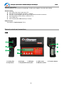
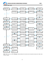
iCharger Synchronous Balance Charger/Discharger 306B Index Specifications ..... ....................................................... ...3 Special Features ... ..........................................................3 Unpack Inspection .. ..........................................................5 External Controls and Connections ...... ......................................5 Warnings and Safety Notes .............. ................................... ...6 Program Flow Chart . ..........................................................7 Keyboard Basics .... ................. ...................................... ...8 Parameter Setup .... ....................................................... ...9 Lithium Battery Program ................ .....................................13 Charging Lithium Battery in BALANCE Mode .................................14 Charging a Lithium Battery in Normal CHARGE Mode .........................15 Fast Charging a Lithium Battery ..........................................15 Pre-charging a Lithium Battery ...........................................16 “Storage” charge/discharge a Lithium Battery ...........................16 Discharging a Lithium Battery.......................................... ...17 Lithium Battery External Expanding Discharge Mode ..................... ...18 Cycle Mode for a Lithium Battery ...................................... ...19 Lithium Battery in Monitoring Mode .................................... ...19 NiCd/NiMH Battery Program ............. .....................................20 Charging a NiCd/NiHM Battery .......................................... ...20 Discharging a NiCd/NiMH Battery ....................................... .. 20 Cycle Mode for a NiCd/NiMH Battery .......................................20 NiCd/NiMH Forming Charge .................................................21 Pb (lead-acid) Battery Program ......... ................................... ..22 Charging a Pb Battery ....................................................22 Discharging a Pb Battery .................................................22 Special Modes Program .................. .....................................23 Electric Motor Drive .................................................. ...23 Foam-Cut Drive ........................................................ ...23 Measuring Internal Resistance of the Battery........................... ...24 Data Save/Load Program ................. .....................................25 Log Files Management....................................................... ..26 General Status Information ............. .....................................27 Warning and Error Information .......... .....................................28 USB Port Interpretation ................ .....................................29 Install USB Driver .......................................................29 Hardware Upgrading Steps .............................................. ...29 Use “logview” for 306B ................................................30 Optional Parts...... ....................................................... ..31 Limited Warranty.... .........................................................32 -2- iCharger Synchronous Balance Charger/Discharger 306B Thank you for purchasing one of the iCharger series. Please read the entire User‘s Manual completely and attentively as it contains a wide variety of specific programming and safety information. Specifications 306B Input voltage range: 4.50 – 38.0VDC Charge current range: 0.05 – 30.0A Discharge current range: 0.05 – 30.0A Maximum charge power capacity: 1000W @ input voltage 23V (500W @ input voltage 12V) Maximum discharge power capacity: 80W Maximum regenerative discharge power capacity:1000W Maximum extern discharge power capacity: 1200W @ 40V/30A Current drain for balancing: <500mA Balance accuracy: <10mV Lithium (LiPo/LiIo/LiFe) battery cell count: 1 – 6 series (In non-balance mode, expand LiFe to 12s) NiCd/NiMH battery cell count: 1 – 25 series Pb battery cell count: 1 – 18 series (2 – 36V) Log Files storage: 16Mbit (31 hours) Battery setup memories: 10 Intelligent temperature control: Yes PC Connect: USB port Weight: 750g Dimensions (L X W X D): 143X123X46mm 5.63‖X4.84‖X1.81‖ Special features High power, high current, high-performance power conversion circuit. The iCharger series uses advanced Synchronous buck-boost DC/DC converter technology with an output conversion efficiency that can reach over 90%. This not only saves power and reduces heat build up but also makes the charger more compact and conveniently mobile. Input power with 4mm bullet connectors butt-welded alligator clips and wide input voltage ranges from 4.5V to 38V. The output power can be adjusted to align with the available input power, thus preventting input current overload and protecting the DC source.The iCharger series can be used with three types of Lithium batteries - LiPo, Lilo, LiFe - and has a fully integrated cell balancer. The fan will start automatically according to the internal temperature and charge/discharge power, and protect the charger if overheated. When the internal temperature is over 55℃(131 oF), the output power is automatically reduced by 25%. If the temperature exceeds 60℃(140 oF) the charge cycle is stopped. Convenient set of 10 battery profile memories that can be saved and loaded by number. 2x16 backlit LCD screen that provides rich information including active mode, current, voltage, total charge (mAh), charging time and temperature etc. Various charging/discharging settings and cycles to meet a wide range of customer needs. For Lithium batteries: balance charging, normal charging, fast charging, storage, discharging, ext-discharging, charge/discharge cycling, and battery monitoring. For NiCd/NiMH batteries: charging-auto, charging-manual, discharging, charge/discharge cycling and forming charge. For Pb batteries: charging and discharging. Up to 1000w unique regenerative discharge capability. Regenerative discharge takes most of the output battery‘s energy and puts it back into the input battery, which is not the same with the traditional methods of discharge to deplete that energy in the form of heat across a transistor. That is, when you discharge your LiPo for storage, you will be re-charging your Lead Acid input battery. The amount of current and voltage that your input battery can accept limit the total amount of power that you can achieve, or 1000W, whichever is lower. Unique Lithium battery expanding discharge program. When you connect the external capacity resistance, you can use it as the maximum discharge power capacity—1200W (@40V/30A). Unique Lithium battery Monitor program. When you use other equipment to charge or discharge a Lithium pack, you can use the iCharger to monitor the per-cell voltages, battery temperature and -3- iCharger Synchronous Balance Charger/Discharger 306B process time. If any individual cell appears over-charged or over-discharged or the pack is too hot or the process has gone on for too long, the iCharger will generate an alarm sound and the related information will blink. Electric motor test mode can be used to run-in electric motors, test motor parameters and performance, check tolerances etc. Foam-cut drive. In this mode, the charger acts as a convenient power supply for a hot wire foam cutter. Battery interior resistance measurement. The iCharger can not only measure the internal resistance of the battery pack, and also can measure the per-cell internal resistance (only available for lithium battery). Perfect protection. The iCharger has protection for reversed polarity (input or output), low input voltage, battery temperature, charging capacity and time overrun. iCharger 306B has a 16Mbit flash storage, which can log offline charge and discharge data in 36 hours. Support upgrading the hardware program by USB port. The iCharger also support the ―logview‖ software and can display, plot and analyze the charge and discharge data by it. (See detail information about logview in the following website: http://www.logview.info) -4- iCharger Synchronous Balance Charger/Discharger 306B Unpack inspection The following items are included in the package. Contact your supplier if any items are missing. Standard items: One copy of the User‘s manual on CD One pair of output alligator clip leads(14AWG) One pair of input alligator clips and input leads with 4mm bullet connectors One temperature sensor lead (0 – 99℃(210 oF)) Four rubber feet One exclusive Mini-USB data line(1.2 meter) Optional items: See details in ―Optional parts‖ (P31) External controls and connections 306B ① ⑥ ② ③ ⑦ ④ ⑧ ⑤ 1. Cooling Fan 6. Output port 2. DC input 3. USB port 7. Temperature sensor port -5- 4. LCD screen 8. Balance socket 5. Function button iCharger Synchronous Balance Charger/Discharger 306B Warnings and Safety notes Keep the charger away from children and pets at all times. Never leave the charger unsupervised when charging or discharging. If you leave, disconnect the battery to prevent any unexpected dangers or damage. Ensure the charger program and settings match the battery pack otherwise the battery will be damaged and a dangerous situation may arise, especially for Lithium batteries, which may cause a fire. Do not mix batteries of different types, different capacities or from different manufacturers. Do not disassemble the charger. Do not place the charger or any battery on a flammable surface or near a combustible material while in use. Do not charge or discharge on a carpet, cluttered workbench, paper, plastic, vinyl, leather or wood, inside an R/C model or inside a full-sized automobile. Never block the air intake holes and never use in a refrigerated or high temperature environment. If used in such an environment, the internal temperature protection may result in abnormal charging/discharging that could be dangerous. Do not allow water, moisture, metal wires or other conductive material into the charger. Never charge or discharge any battery having evidence of leaking, expansion/swelling, damaged outer cover or case, color-change or distortion. Do not try to charge ―non-rechargeable‖ dry cells. Do not exceed the battery manufacturer‘s suggested maximum charge rates. Beware that the external case temperature of the charger will increase during charging/discharging at high power. Carefully follow the battery pack manufacturer‘s recommendations and safety advice. Recommended connecting way: 1. Connect iCharger's input power supply, and turn on it. 2. Connect Li batteries' balance port 3. Connect the main charging port's positive pole to cells' positive pole, and then connect negative pole to cells' negative pole (this will avoid striking fire while connecting Li cells). 4. Start charging and discharging... 5. After finishing charging and discharging, pls disconnect the cell and charger, and then turn off the charger's power supply. Standard battery parameters Nominal voltage Max. charge voltage Storage voltage Allowable fast charge current Min. discharge voltage LiPo 3.7 V/cell 4.2 V/cell 3.85 V/cell ≤ 1C LiIo 3.6 V/cell 4.1 V/cell 3.75 V/cell ≤ 1C LiFe 3.3 V/cell 3.6 V/cell 3.3 V/cell ≤ 4C NiCd NiMH Pb 1.20 V/cell 1.20 V/cell 2.0 V/cell 1.60 V/cell 1.60 V/cell 2.45 V/cell n/a n/a n/a 1C – 2C 1C – 2C ≤ 0.4C ≥ 3.0 V/cell ≥ 2.5 V/cell ≥ 2.0 V/cell ≥ 0.85V/cell ≥ 1.0 V/cell ≥ 1.75V/cell cut-off level cut off level Note: Be very careful to choose the correct voltage for different types of battery otherwise you may cause damage to the batteries. Incorrect settings could cause the cells to vent, burn or explode leading to injury or loss of property. -6- iCharger Synchronous Balance Charger/Discharger 306B Program flow chart PROGRAM SELECT Lithium battery Start Inc LiXX CHARGE Inc LiXX FAST CHARGE Inc LiXX STORAGE Enter LiXX BALANCE CHG X.XA AUTO Dec X.XA XX.XV(XS) Dec X.XA XX.XV(XS) Dec X.XA XX.XV(XS) Inc Dec Batt type Inc Dec Inc LiXX CYCLE LiXX MONITOR X Inc LiXX DCHG+ X.XXV Inc LiXX DCHG X.XXV X.XXV XX.XV(XS) Dec X:X.XXV->X:X.XXV Dec X.XA AUTO Dec X.XA XX.XV(XS) X NiMH FORMING CHG X.XA XX.XV(XS) Inc Start PROGRAM SELECT Enter NiMH battery Batt type Dec Inc Start PROGRAM SELECT Enter NiCd battery Batt type Dec Inc Start PROGRAM Enter Dec SELECT Inc Pb battery Dec Inc NiMH CYCLE NiMH CHARGE Aut Inc NiMH CHARGE Man Inc NiMH DISCHARGE X X.XA CUR LIMIT Dec X.XA CURRENT Dec X.XA XX.XV Dec XXX(XXX)->XXXX Inc NiCd CYCLE NiCd CHARGE Aut Inc NiCd CHARGE Man Inc NiCd DISCHARGE X X.XA CUR LIMIT Dec X.XA CURRENT Dec X.XA XX.XV Dec XXX(XXX)->XXXX X Inc Dec Inc Pb DISCHARGE Pb CHARGE X.XA XX.XV(XS) Dec X.XA XX.XV(XS) NiCd FORMING CHG X.XA XX.XV(XS) Batt type Inc Start Inc Bal.Speed XXXXXX Inc Li Balance ON PROGRAM SELECT Enter Lithium battery Settings -> Check Time XXmin Dec Bal.Trickle XXX Dec XXX Dec Inc Wait Time Dec CHG/DCHG XXmin Inc Dec NiMH/NiCd Check Inc NiCd Sensitivity Inc NiMH Sensitivity Inc NiMH/NiCd/Pb Delay XXmin Dec DeltaV XXmV/Cell Dec DeltaV XXmV/Cell Dec Trickle XXXmA Inc Batt type Dec Inc Dec Inc Safety timer Inc Capacity Cut-Off Inc Input limit XX.X Temp. Cut-Off XXX XX℃ Dec XXX XXXmin Dec XXX XXXXXmAh Dec Cut-Off XX.XXV Inc Back-light XX% Inc Completion Ring Cooling fan XXXX Dec Beep XXX Inc Inc Key Beep Dec Buzzer Dec XXX Inc Watt Limit (W) XXX Dec CHG:XXXX DCHG:XX Dec Discharge reduce Inc Regenerative DSC Inc LiFe Termination Inc Lilo Termination OFF XX% Dec XXX XX.XA XX.XXV Dec Voltage X.XXV Dec Voltage X.XXV Inc Start Inc FOAM PROGRAM SELECT Enter MOTOR DRV XXmin Special modes X.XA XX.XV Dec X.XA Batt type Dec Inc Start PROGRAM SELECT Enter SAVE SETTINGS XX Save settings memoryX Batt type Inc Dec Start PROGRAM SELECT Enter LOAD SETTINGS XX Load settings memoryX CUT XXmin Inc Measure Internal XX.XV Dec resistance Dec LiPo Termination Voltage X.XXV Inc Dec Pb Termination Voltage X.XXV Note: When you turn off the iCharger it will remember the current menu and start from that menu when next turned on again. -7- iCharger Synchronous Balance Charger/Discharger 306B Keyboard basics 1. Go to the main menu, press the Inc button or the Stop/Batt type button to go down, and press the Dec button to go up: press the Start/Enter button to enter a sub-menu. 2. In a sub-menu, press Start/Enter to blink the chosen item, and then alter the value with Inc or Dec. With nothing blinking you can go to the sub-menu below with Inc and above with Dec. Press Stop/Batt type to go back to the previous screen. 3. In some sub-menus, press and hold Start/Enter for more than 3 seconds to start the process, such as starting charging or discharging. 4. During the charging/discharging process you can terminate the process at any time by pressing Stop/Batt type and check the attached information with IncorDec. Press Start/Enter to go back to the main information screen. 5. During the discharge process, press Start/Enter to alter the discharge current. When the discharge current blinks, press Inc to increase it or Dec to decrease it, then press Start/Enter to confirm the change. 6. Press Stop/Batt type for more than 3 seconds to start the display of the active test information as per the following diagram. Present testing information: In this display the output voltage is the idle voltage measured at the output terminals (that is, the voltage of the connected battery pack). Stop/Batt type Pressing Start for 3 seconds to monitor the resistance again. >3 seconds Vi11.94V Int30℃ Vo 8.23V Ext25℃ Output Volt. Input Int. Ext. Volt. Temp. Temp. Inc 1:4.11 4.12 ---4:---- ---- ---7. 1: 21 4: 24 mΩ mΩ Per cell resistance from the balance port. Dec Battery Pack IR 45mΩ Pack cells resistance from the balance port. Individual cell voltage from the balance port. Reset to Defaults function. Press Stop/Batt type and Start/Enter together for more than 3 seconds to obtain this display: Resume defaults? CONFIRM (ENTER) 8. Dec Press Start/Enter to reset all values to the system-default settings. Adjust Current, Temp. Cut-Off, Safety timer, Capacity Cut-Off in course of charging and discharging. Method of Application: When in charging and discharging interface, press Start/Enter for 3 seconds, and current begins blinking. Press IncorDec to adjust current, and press Start/Enter to save changes. If users press Stop/Batt type or without any operation for 1 minute, it will cancel and quit from the changes. Note: Adjustment of current is only effective for charging and discharging, which will not saved as user setting. When in charging and discharging interface, press Dec for several times to see need-to-be changed information interface. Press Start/Enter for 3 seconds, and the value begins blinking. The adjust method is as same as the above. Note: This change can be saved as user setting. -8- iCharger Synchronous Balance Charger/Discharger 306B Parameter setup Users should check the parameter settings and adjust the parameter values according to the specifications of the pack to be charged or discharged. Note: The screen diagram on the left shows the system‘s default setting. PROGRAM SELECT Settings -> Start/Enter Lithium battery Check Time 1min + Dec Inc Dec Inc Bal.Speed Normal Bal.Trickle OFF + Dec Inc Dec Inc Li Balance ON CV phase + Dec Inc Dec Inc Wait Time CHG/DCHG Dec Inc 10min + Dec Inc NiMH/NiCd/Pb Trickle OFF Dec Inc Inc iCharger checks the cell count of Lithium batteries automatically at the beginning of the charge or discharge process in order to detect and avoid erroneous setting by the user. However, deeply discharged batteries can be perceived incorrectly. To avoid this problem you can set an initial time during which to charge the battery at a low current, usually 100mA. Normally 10 minutes is enough to detect the cell count correctly. For batteries of different capacities, you should adjust the time delay. Note: If you set the time delay too long for a low capacity battery then the charging process can be finished within the time delay with an erroneous cell count, which may damage the battery and could be dangerous. Range: 1 – 10 min. (1min, default) For balance charging Lithium batteries. If the Bal. Speed is set to Fast, the CV termination current will be higher, the charging time shorter and the per-cell voltage lower. When set to Slow, the CV termination current will be lower, the charging time longer and the per-cell voltage higher. The default value of Normal is between the Fast and the Slow. If Bal. Trickle is ON, the iCharger won‘t stop charging until the current falls to around 20mA. Bal.Speed: Fast, Normal & Slow, (Normal, default). Bal.Trickle: OFF & ON: (OFF, default) For balance charging Li battery. There are three balance modes options: CV phase, storage voltage and always. If the balance mode is set to CV phase, when any cell‘s voltage reaches the set voltage for CV, it will enable the balancer. When set to ―always‖, the balancer will be enabled from the beginning of the charge process. When set to ―storage voltage‖, the balancer will be enabled when any cell‘s voltage exceeds the default storage voltage for the configured chemistry. Balance mode: CV phase, storage voltage, always (CV phase, default) When running a charge/discharge cycle program for a Lithium, NiMH or NiCd battery the charger will stop for a while before continuing to the next phase. This allows the pack to cool down. Range: 1 – 60 min. (10 min default) You can turn post charge-completion trickle charging. On or Off for NiMH, NiCd or Pb batteries. Range: OFF, 10 – 500mA. (OFF,default) + Dec Inc NiMH Sensitivity DeltaV Default Dec User parameter setup initial display. + Dec Inc Usually, the NiMH battery voltage will drop a little right after reaching full charge. This is known as -△V. You can alter the iCharger‘s delta-peak detection sensitivity. Range: 1 – 20mV/Cell. (4mV/Cell, default) -9- iCharger Synchronous Balance Charger/Discharger Dec Inc + Dec Inc NiMH/NiCd Check Delay 0min Dec Inc + Dec Inc Temp. Cut-Off ON 50℃ + + Dec Inc Dec Inc Dec Inc Safety timer ON 120min + + Dec Inc Dec Inc Dec Inc Capacity Cut-Off ON 5000mAh + + Dec Inc Dec Inc Dec Inc Input limit 50.0 Cut-Off 4.50V Dec + Inc Dec Inc Watt Limit (W) CHG:AUTO DCHG:60 + Dec Inc Dec + Dec Inc Inc Usually, the NiCd battery voltage will drop a little right after reaching full charge. This is known as -△V. You can alter the iCharger‘s delta-peak detection sensitivity. Range: 1 – 20mV/Cell. (8mV/Cell, default) When NiMH&NiCd batteries are deeply discharged or left unused for a long time, they will produce a false -△V which stops charging early. You can disable -△V testing to avoid this problem. Range: 0 – 30min (0, default) Battery upper temperature limit. The battery temperature can be monitored with the attached temperature sensor. In order to protect the battery from damage due to high temperatures the iCharger will stop charging or discharging immediately if the temperature exceeds the cut-off setting. Users can choose ℃ or oF as the temperature unit Range: 20 – 80℃(68 – 176 oF). oF = (9/5)×℃+32. Charging time upper limit. The charging process will stop immediately if it exceeds the set value. Range: 1 – 999min Capacity protection. The charging/discharging process will stop immediately if the calculated charge input/drained exceeds the set value. Range: 100 – 99900mAh Input current limit & Input voltage protection lower limit. The charging/discharging process will stop immediately if the input voltage falls below the set value. Voltage Range: 4.50 – 32.00V (4.50V, default) Current Range: 1.0A – 50.0A(50.0A, default) Note: Current limit is not very accurate, which may be 20% difference, max. Charge/Discharge power limit. The maximum charge/discharge power of iCharger can be adjusted in order to limit internal temperature and to protect the input current from over-loading. When the limit is set to AUTO the iCharger can adjust the output charging power according to the input capability. CHG: 50 –1000W and AUTO. DCHG: 5 –80W(60 W, default) Note: The maximum charge power capacity is also limited by input current. The maximum input current of 306B is about 50A, and Wmax ≈ Imax * Vin * 90%. (For example, when the input voltage is 15V, the maximum charge power capacity ≈50×15×90%=675W). iCharger306B: MAX. OUTPUT POWER vs. INPUT VOLTAGE Max. Output power(W) NiCd Sensitivity DeltaV Default 306B 1000 900 800 700 600 500 400 300 200 100 5 7 9 11 13 15 17 19 21 23 25 27 29 31 33 35 37 Input voltage(V) -10- iCharger Synchronous Balance Charger/Discharger Key Beep Buzzer Dec Key confirmation and alert tone. If the keyboard sound is ON there will be a beep when you press any key. If the buzzer is ON the iCharger will generate an alert tone for certain events. Key Beep: OFF&ON: (ON, default) Buzzer: OFF&ON: (ON, default) ON ON + Dec Inc Inc Process completion tone. Controls the tones generated at end of charging or discharging and the cyclic charging/discharging indication. Options: Beep 5 times, Beep 3 minutes, Beep always (continuous until user presses STOP), Beep OFF (Beep always, default) Completion Ring Beep always Dec + Dec Inc Inc Back-light and cooling fan control. Adjust the LCD backlight brightness. There are three cooling fan modes: ON, OFF, AUTO. In AUTO-Mode, iCharger adjusts the fan automatically to control its internal temperature. Cooling fan: OFF, ON & AUTO (AUTO, default) Back-light 50% Cooling fan AUTO Dec + Dec Inc Inc Discharge reduce setting. When you set it to ―ON‖,If the final voltage target storage voltage is reached, the buzzer will beep for three times, and the left of the second line display "D>>", and the charger enters into the high precision discharge process. The process won‘t stop until the current reaches xx% of the configured discharge current. Reduce: ON, OFF Range: 1 – 99% Discharge reduce OFF 50% + + Delay 0min Dec Inc Dec Inc Dec 306B Inc Regenerative discharge setting. In the second line, these items are set: Regenerative discharge ON/OFF, current limit, voltage limit. Regenerative discharge: OFF, ON (OFF, default) Regenerative current limit: 1 – 30A (1A, default) Regenerative voltage limit: 4.50 – 37.0V (4.50V, default) Regenerative DSC OFF 1.0A 4.50V - + -Delay + + 0min Dec Inc Dec Inc Dec Inc Dec Inc When Regenerative discharge is set to ON, discharging by charger internal consumption turns to charging power supply (current and voltage limit can be set), which is shown in the following graph. + + Power Supper Regenerative DSC: OFF Input - - Output iCharger + + Rechargeable Power Supper Discharge User Batt. Current - - For example: Pb battery etc. Pack Regenerative discharge OFF + + Regenerative DSC: ON Input - - Output iCharger + + Discharge User Batt. Current - - Pack Regenerative discharge ON Note: 1. When in Regenerative discharging, charger‘s power supply needs to be rechargeable. For example, Pb battery can be used for input power supply, but switch power adapter cannot. 2. The setting of regenerative discharge‘s current and voltage limit should be suit for power supply. For example, using 12V Pb battery as power supply, the regenerative current and voltage should not be more than its max charging current and voltage, or it may cause danger. 3. Regenerative discharge max power is the same with charger‘s setting max charging power, not discharging power. (Restricted by setting regenerative discharge current and voltage limit, and discharge current limit.) 4. Regenerative current limit is not very accurate, which may be 20% difference, max. 5. If input power supply voltage is more than setting regenerative limit voltage, charger will not start regenerative discharge and internal discharge instead. -11- iCharger Synchronous Balance Charger/Discharger Dec Inc LiFe Termination Voltage 3.60V + Delay 0min Dec Inc Dec Inc + Dec Inc LiPo Termination Voltage 4.20V Dec Termination voltage for LiFe. Adjust LiFe‘s charge termination voltage. Press Start/Enter for more than 3 seconds to blink the ―Voltage‖ value, then press Dec and Inc to adjust the termination voltage. Range: 3.40V – 3.90V, Step: 0.01V (3.60V, default) Inc Lilo Termination Voltage 4.10V Dec 306B Inc + Dec Inc Pb Termination Voltage 2.40V + Dec Inc Termination voltage for Lilo. Adjust Lilo‘s charge termination voltage. Press Start/Enter for more than 3 seconds to blink the ―Voltage‖ value, then press Dec and Inc to adjust the termination voltage. Range: 3.90V – 4.20V, Step: 0.01V (4.10V, default) Termination voltage for LiPo. Adjust LiPo‘s charge termination voltage. Press Start/Enter for more than 3 seconds to blink the ―Voltage‖ value, then press Dec and Inc to adjust the termination voltage. Range: 4.00V – 4.30V, Step: 0.01V (4.20V, default) Termination voltage for Pb. Adjust Pb‘s charge termination voltage. Press Start/Enter for more than 3 seconds to blink the ―Voltage‖ value, then press Dec and Inc to adjust the termination voltage. Range: 2.20V – 2.50V, Step: 0.01V (2.40V, default) Note: The Termination voltage controls the transition from Constant Current (CC) to Constant Voltage (CV) charging for LiXx and Pb chemistries. It also defines the per-cell limit for cell overvoltage detection. If you change the default termination voltage, the charge and discharge setting screen will note this difference by alternatively blinking battery‘s type and setting voltage value. -12- iCharger Synchronous Balance Charger/Discharger 306B Lithium battery program The iCharger provides a number of Lithium programs including Balance, Normal, Fast and Storage. Only the Balance mode requires the balance lead connected. However, the other modes will provide additional per-cell over-voltage protection if the balance lead is connected compared to running them without it, where they can only utilize the total pack voltage. Balance connector required Yes Balancer active Yes Icv = Icc/10 OR Vout = (cell_count x cell_max_voltage) + Vloss Balance – Fast Yes Yes Icv = Icc/5 OR Vout = (cell_count x cell_max_voltage) + Vloss Balance – Slow Yes Yes Icv = Icc/40 OR Charge Optional No Icv = Icc/10 AND Vout = cell_count x cell_max_voltage Fast Charge Optional No Icv = Icc/5 AND Vout = cell_count x cell_max_voltage Storage Optional No Vout = cell_count x cell_storage_voltage Cycle - charge Optional No Icv = Icc/10 Balance – Normal Charge termination condition Vout = (cell_count x cell_max_voltage)+ Vloss AND Vout = cell_count x cell_max_voltage Cycle - discharge Optional No Vout = cell_count x cell_discharge_voltage Icc = configured charge current for the CC phase Icv = charge current during the CV phase cell_max_voltage = configured termination voltage for the selected chemistry (eg LiPo = 4.2V) cell_storage_voltage = configured per-cell storage voltage for the selected chemistry cell_discharge_voltage = configured per-cell storage voltage for the selected chemistry Icv = charge current during the CV phase Vloss = 0.2 * (1 + Icv/10A); when in balance charging, charging line loss will compensate voltage. Any time the battery‘s balance lead is connected the charger will monitor and display the cell voltages. The balancer is only active during a BALANCE charge (not during the CHARGE or FAST programs) The balance speed setting (Slow, Normal, Fast) controls the end-of-charging current threshold. The CHARGE and FAST modes are identical except for the charge-termination threshold which is 1/10 of the charge current setting for CHARGE and 1/5 of the charge current setting for FAST mode. While the CHARGE and FAST modes do not include any balancing action it is still safer to have the balance lead connected since then the charger will provide per-cell over-voltage protection as described below. In all kinds of charge cycle, if the balance lead is connected and if any cell exceeds the allowable per-cell peak voltage for the configured chemistry, the charge current will be reduced to ensure the voltage does not rise any further. This will slow the charging process and if the charge current falls to 1/10 of the charge current setting this will result in the charge cycle stopping altogether. Note that this is not the normal CC-to-CV transition which would usually occur when all cells approach the nominal peak voltage for the configured chemistry, but is a safety measure to respond to unbalanced cells in any mode or at any time during the charge process. Note: When Li batteries are in balance charging, charger's max output voltage = (cell_count x cell_max_voltage) + Vloss When connecting the Li batteries with main output port and the balance port, the charger will check cell count automatically, and forbid changing cell count setting by user himself. This is useful for all Li batteries‘ charging and discharging mode. -13- iCharger Synchronous Balance Charger/Discharger 306B Charging Lithium battery in BALANCE mode This function is for balancing the voltage of Lithium-polymer battery cells while charging. In the balance mode the battery balance lead must be connected to the balance port on the right side of the iCharger. The pinout of the balance port is shown in the diagram below. Charging in this mode is different from the normal CHARGE mode because the iCharger can monitor the voltage of individual cells and adjust the input current fed into each cell to normalize the voltage (for example: LiPo battery within 4.2V). Balance charging mode of Lithium battery. The left side of the first line set the type of battery (LiPo, Lilo or LiFe). The value on the left side of second line sets the charge current and on the right side of second line, it shows AUTO. The system will check cell count automatically by cell balance port's voltage. Charge current: 0.05 – 30A, Voltage: 1 – 6 series LiPo BALANCE CHG 1.0A AUTO + Dec Inc + Dec Inc Batt type stop Start/Enter >3 seconds Li03 1.0A 12.60V BAL 00993 59m:51 work charged charging State capacity time number charge battery of cells current voltage Lithium BALANCE charging mode. The screen shows the status during the charging process. You can stop charging at any time by pressing Batt type/Stop.Press Inc to display each cell‘s voltage (see the balance voltage information) and press Dec to display the General Status Information. Series Balance port and Individual Cell connection diagram OUTPUT - OUTPUT - - 1S + 2S + 3S + 4S + 5S - 6S + 1S + 2S + 3S + OUTPUT + + Balance port OUTPUT + 306B Notice: Don't plug multiple battery balance sockets into the balance port of 306B, or else it may burn the balance port. If charging the battery pack in series, the balance connector conversion board is a must. ( See P31 ) -14- iCharger Synchronous Balance Charger/Discharger 306B Charging a Lithium battery in normal CHARGE mode The iCharger first charges with constant current (CC) according to the user setting then constant voltage (CV) when the charging voltage reaches the peak point. In the CV phase the current gradually falls. The iCharger will terminate charging when the current falls below than 1/10 of the configured charge current. LiPo CHARGE 1.0A 11.1V(3S) + + Dec Inc Dec Inc + Dec Inc Batt type Start/Enter stop >3 seconds R:02SER S:03SER CONFIRM(ENTER) Batt type Start/Enter stop Battery Charge V-BP Series 1.0A Current12.60V Li03 CHG 00993 59m:51 work charged charging State capacity time number charge battery of cells current voltage The left side of the first line set the type of battery (LiPo, Lilo or LiFe). The value on the left side of second line sets the charge current and the value on the right side of second line sets the cell count and voltage of the battery pack. After setting the current and voltage, press Start/Enter for more than 3 seconds to start the next process. Charge current: 0.05 – 30A, Voltage: 1 – 6 series ( LiFe to 12 series) The number of cells you set and the processor detects. If the checking result is the same, it would enter to the next interface; if not the same, the left side of the first line ‘R:xxSER‘ shows the number of cells detected by the iCharger and the right side of the first line ‘S:xxSER‘ is the number of cells set by the user. Usually, the auto-detect number won‘t exceed the number set by the user. You should make sure that the configured number and the actual number for the battery are the same and then you can start charging by pressing Start/Enter. If not, press Batt type/Stop to go back to the previous screen and adjust the setting. Lithium CHARGE mode. The screen shows the status during the charging process. You can stop charging at any time by pressing Batt type/Stop. Press Inc to display each cell‘s voltage (see the balance voltage information) and press Dec to display the General Status information. Fast charging a Lithium battery The Series iCharger first charges with constant current (CC) according to the user setting then constant voltage (CV) when the charging voltage reaches the peak point. In the CV phase the current gradually falls. The iCharger will terminate charging when the current falls below than 1/5 of the configured charge current. This will result in slightly less than 100% charge but will complete sooner than the Normal charge mode. LiPo FAST CHARGE 1.0A 11.1V(3S) + + Dec Inc Dec Inc + Dec Inc Batt type Start/Enter stop >3 seconds R:02SER S:03SER CONFIRM(ENTER) Batt type Start/Enter stop Battery Charge V-BP Series 1.0A Current12.60V Li03 FST 00993 59m:51 work charged charging State capacity time number charge battery of cells current voltage Series The fast charging mode of Lithium battery. The left side of the first line set the type of battery (LiPo, Lilo or LiFe). The value on the left side of second line sets the charge current and the value on the right side of second line sets the cell count and voltage of the battery pack. After setting the current and voltage, press Start/Enter for more than 3 seconds to start the next process. Charge current: 0.05 – 30A, Voltage: 1 – 6 series ( LiFe to 12 series) The number of cells you set and the processor detects. If the checking result is the same, it would enter to the next interface; if not the same, the left side of the first line ‘R:xxSER‘ shows the number of cells detected by the iCharger and the right side of the first line ‘S:xxSER‘ is the number of cells set by the user. Usually, the auto-detect number won‘t exceed the number set by the user. You should make sure that the configured number and the actual number for the battery are the same and then you can start charging by pressing Start/Enter. If not, press Batt type/Stop to go back to the previous screen and adjust the setting. Lithium FAST charging mode. The screen shows the status during the charging process. You can stop charging at any time by pressing Batt type/Stop. Press Inc to display each cell‘s voltage (see the balance voltage information) and press Dec to display the General Status Information. -15- iCharger Synchronous Balance Charger/Discharger 306B Pre-charging a Lithium battery If the battery is over-discharged and the voltage is too low then in the Normal charge or Fast charge modes the iCharger will notify the user of pre-charging with a low current (100mA). This helps to increase the battery voltage to the within the allowable range for normal charging. The user can set the pre-charging time in the Lithium Check time screen in the User setup. Pre-charging battery Do checking? CONFIRM(ENTER) The following screen is displayed when the charger detects the battery voltage to be too low in the Normal charge or Fast charge modes. Pre-charge lithium battery. Press Start/Enter to start the charging process or press Stop to go back to the previous screen. Batt type Start/Enter stop Status display. The left side of the first line shows the type of battery (LiPo, Lilo or LiFe) and number of cells detected. In the middle is the pre-charge Li03 0.1A 12.40V current (100mA). On the right is the voltage of the battery pack. The second CHK 00001 00m:51 line shows the charging progress with capacity charged (mAh) and charging time. The charger will switch back to the configured charge mode when the work charged charging state capacity time pre-charge time limit is reached. You can stop the pre-charging process at battery of 0.1A battery any time by pressing the Batt type/Stop button. cells test pre-charge current online voltage “Storage” charge/discharge a Lithium battery This mode is for charging/discharging a Lithium battery that is not to be used for an extended period. The program determines whether to charge or discharge the battery based on the configured target voltage and the measured initial voltage of the battery. The nominal target storage voltage depends on the type of Lithium battery: 3.75V/cell for Lilo, 3.85V/cell for LiPo and 3.3V/cell for LiFe. If at the start the battery voltage exceeds the target storage voltage the program will start to discharge rather than charge. LiPo STORAGE 1.0A 11.1V(3S) + Dec Inc + Dec Inc Batt type stop + Dec Inc Start/Enter >3 seconds R:03SER S:03SER CONFIRM(ENTER) Batt type Start/Enter stop Battery Charge V-BP Series 1.0A Current12.60V Li03 STO 00993 59m:51 work charged charging state capacity time number charge battery of cells current voltage Storage of Lithium battery. The left side of the first line set the type of battery (LiPo, Lilo or LiFe). The value on the left side of second line sets the charge/discharge current and the value on the right side of second line sets the cell count and voltage of the battery pack. After setting the current and voltage, press Start/Enter for more than 3 seconds to start the next process. Charge current: 0.05 – 30A, Voltage: 1 – 6 series The number of cells you set and the processor detects. If the checking result is the same, it would enter to the next interface; if not the same, the left side of the first line ‘R:xxSER‘ shows the number of cells detected by the iCharger and the right side of the first line ‘S:xxSER‘ is the number of cells set by the user. You should make sure that the configured number and the actual number for the battery are the same and then you can start charging by pressing Start/Enter. If not, press Batt type/Stop to go back to the previous screen and adjust the setting. Lithium STORAGE charging mode. The screen shows the status during the charging process. You can stop charging at any time by pressing Batt type/Stop. Press Inc to display each cell‘s voltage (see the balance voltage information) and press Dec to display the General Status information. eries -16- iCharger Synchronous Balance Charger/Discharger 306B Discharging a Lithium battery In this mode, you can set the target per-cell voltage and hence the final voltage (final voltage=cell voltage*number of cells). The lowest allowable cell voltage depends on the type of Lithium battery: 2.50V for Lilo, 3.00V for LiPo and 2.00V for LiFe per cell. If the battery is connected to the balance port, the iCharger can monitor the individual cell voltages. The discharge will stop immediately if any cell falls below the configured final voltage. LiPo DCHG 3.30V 1.0A 11.1V(3S) + Dec Inc + Dec Inc Batt type stop + Dec Inc Start/Enter >3 seconds R:04SER S:03SER CONFIRM(ENTER) Batt type Start/Enter stop Battery Charge Discharge Lithium battery. The left side of the first line set the type of battery (LiPo, Lilo or LiFe) and the value on the right side shows the final discharge voltage of each cell. The value on the left side of second line sets the charge current and the value on the right side of second line sets the cell count and voltage of the battery pack. After setting the current and voltage, press Start/Enter for more than 3 seconds to start the next process. Per-cell final voltage: LiPo (3.00 – 4.20V), Lilo (2.50 – 4.10V), LiFe (2.00 – 3.60V) Discharge current: 0.05 – 30A , Cell count: 1 – 6S The number of cells you set and the processor detects. If the checking result is the same, it would enter to the next interface; if not the same, the left side of the first line ‘R:xxSER‘ shows the number of cells detected by the iCharger and the right side of the first line ‘S:xxSER‘ is the number of cells set by the user. Usually, the auto-detect number won‘t lower than the number set by the user. You should make sure that the configured number and the actual number for the battery are the same and then you can start charging by pressing Start/Enter. If not, press Batt type/Stop to go back to the previous screen and adjust the setting. V-BP Series 1.0A Current12.60V Li03 DSC 00993 59m:51 work discharge discharging state capacity time number discharge battery voltage of cells current Discharge process. The iCharger allow its user to alter the discharging current during the process. Press Start/Enter to make the discharge current blink then press Inc to increase or press Dec to decrease the value and press Start/Enter to confirm the alteration. You can stop discharging at any time by pressing Batt type/Stop. Press Inc to display each cell‘s voltage (see the balance voltage information) and press Dec to display the General Status information. Note: If you connect the balance port at the beginning of the discharging process, then the balance port will Series monitor each cell‘s voltage, if one of these cells‘ voltage reaches the termination voltage then the process will terminate with ―balance port low cel vol‖. For example in LiPo mode, if one cell‘s voltage reaches 3.0V the process will stop. If you want to avoid this ―balance port low cell vol‖ message, then you can connect the balance port after the discharge process has started. In that case the process won‘t monitor each cell‘s voltage, just the pack‘s voltage and the discharge process will terminate when the pack voltage reaches the termination voltage (= target_cell_voltage x number_of_cells). For example in LiPo mode, the discharge process won‘t terminate until the pack‘s voltage reach N*3.0V. -17- iCharger Synchronous Balance Charger/Discharger 306B Lithium battery external expanding discharge mode You can expand the iCharger‘s discharge power capacity by connecting the external capacity resistance. What should pay special attention is that, when expanding discharge, the balance port must connect to the battery and the expanding capacity resistance R should be series connected to the positive pole (See in the following diagram) Output iCharger + R - Lixx Batt. + Pack Bal. port LiPo DCHG+ 3.30V 1.0A AUTO + Dec Inc + Dec Inc Batt type stop Start/Enter >3 seconds Li03 1.0A 12.60V DSC 00993 59m:51 work discharge discharging state capacity time number discharge battery of cells current voltage Discharge Lithium battery. The left side of the first line set the type of battery (LiPo, Lilo or LiFe) and the value on the right side shows the final discharge voltage of each cell. The value on the left side of second line sets the discharge current and on the right side of second line, it shows AUTO. The system will check cell count automatically by cell balance port's voltage. Per-cell final voltage: LiPo (3.00 – 4.20V), Lilo (2.50 – 4.10V), LiFe (2.00 – 3.60V) Discharge current: 0.05 – 30A, Cell count: 1 – 6S Discharge process. The iCharger allow its user to alter the discharging current during the process. Press Start/Enter to make the discharge current blink then press Inc to increase or press Dec to decrease the value and press Start/Enter to confirm the alteration. You can stop discharging at any time by pressing Batt type/Stop. Press Inc to display each cell‘s voltage (see the balance voltage information) and press Dec to display the General Status information. Series In this mode, the lithium battery discharges through iCharger and R, P = Pi + Pr, (Pi is charger‘s wasted power capacity; Pr is wasted power capacity by resistance). Pi is limited by the set charger‘s maximum discharge power capacity(<80W). But in the first 30 seconds of discharge startup, Pi can be reached 150W. This characteristic is tend to active some resistance loads which shows a remarkably increase in resistance value along with increase of the temperature, such as bulbs. In Expanding Discharging Mode, if starts Regenerative discharge at the same time( see details in Page 11), the above stated Pi restrict will alter less than 1000W. External capacity resistance‟s setting: R = Vbat / Iset; P = Vbat * Iset; R:The value of the external capacity resistance P:Rating capacity of the external capacity resistance For example: discharge a pack of 20V lithium battery at 7A R = 20V / 7A = 2.85Ω P = 20V×7A = 140W -18- iCharger Synchronous Balance Charger/Discharger 306B Charge-to-discharge & Discharge-to-charge cycle mode for a Lithium battery LiPo CYCLE 3 C:4.20V->D:3.00V + Dec Inc + Dec Inc + Dec Inc Batt type Start/Enter stop >3 seconds R:02SER S:03SER CONFIRM(ENTER) Batt type Start/Enter stop Battery Charge V-BP Series 1.0A Current12.60V Li03 C>D 00993 59m:51 work cycle cycle state capacity time number cycle battery of cells current voltage Charging/discharging cycle mode of Lithium battery. The left side of the first line sets the type of battery (LiPo, Lilo or LiFe) and the right side shows the cycle number. The second line shows the cycle direction you selected: (C: x.xxV->D: x.xxV) or (D: x.xxV->C: x.xxV), the value of the second line sets the final charge/discharge voltage. Press Start/Enter button for more than 3 seconds with a sound ‖Di‖ to start the next process. Cycle number: 1 – 999 (only last 10 times cycle information will be displayed) Voltage: LiPo (3.00 – 4.20V), Lilo (2.50 – 4.10V), LiFe (2.00 – 3.60V) The number of cells you set and the processor detects. If the checking result is the same, it would enter to the next interface; if not the same, the left side of the first line ‘R: xxSER‘ shows the number of cells detected by the iCharger and the right side of the first line ‘S:xxSER‘ is the number of cells set by the user. You should make sure that the configured number and the actual number for the battery are the same and then you can start charging by pressing Start/Enter. If not, press Batt type/Stop to go back to the previous screen and adjust the setting. Charging/discharging cycle mode of Lithium battery. In this process, you can stop the cycle at any time by pressing the Batt type/Stop button. In the process of C>D or D>C, the blink ―C‖ indicates charging, while ―D‖ indicates discharging. Press Inc button to display each cell‘s voltage and its past cycling current (see the balance voltage information& cycling information) and press Dec button to display the General Status information. During the waiting time of discharge-to-charge cycle mode, you can stop the waiting process with pressing ―Start" button for three seconds! Series Lithium battery in monitoring mode When you use other devices to charge or discharge Lithium pack, the iCharger can monitor each cell‘s voltage, battery temperature, charge time and so on, if one of the batteries appears over-charged, over-discharged, over-hot, over-capacity or over-time ,the iCharger will alarm with noise “Di…..” and blink the raleted information. LiPo MONITOR 3.0V 11.1V(3S) + + Dec Dec Inc - Inc + Dec Inc Batt type Start/Enter stop >3 seconds Battery Charge V-BP Series 50℃ Current12.60V Li03 Monitor 50m:43 run work time state number Ext. battery of cells temperature voltage Monitor mode of Lithium battery. The left side of the first line sets the type of battery (LiPo, Lilo or LiFe). The value on the right side of the second line sets the low limit of voltage and the battery pack number. After setting the current and voltage press Start/Enter button for more than 3 seconds with a sound ‖Di‖ to start the next process. Individual alarm low-Vt: final discharging voltage to the highest charging voltage (such as: LiPo 3.0V – 4.2V), Battery series: 1 – 10 series The monitor information, in this process; you can stop monitoring process at any time by pressing Batt type/Stop button. Press Inc button to display each cell‘s voltage (see the balance voltage information), the iCharger will alarm with noise “Di….”when any errors appear. Note: when in Li monitor Mode, no need connecting the main port if connecting the balance port. Series -19- iCharger Synchronous Balance Charger/Discharger 306B NiCd/NiMH battery program Charging a NiCd/NiHM battery NiMH CHARGE Aut 1.0A CUR LIMIT + Dec Inc Batt type Start/Enter stop >3 seconds NiMH 1.0A 10.45V CHG 00993 59m:51 The left side of the first line displays the type of battery (NiCd/NiMH) and the second line allows you to set the current limit. The iCharger offers two charging modes for NiCd/NiMH., ‗CHARGE Aut‘ and ‗CHARGE Manual‘. In ‗Aut‘ mode the user sets the upper limit for the charging current. The iCharger will charge with about 1C automatically but no higher than the configured current. In ‗Manual‘ mode it will charge at the configured current. Press Start/Enter for more than 3 seconds to start charging. Current for Aut: 0.05 – 30A; Current for Manual: 0.05 – 30A Charge status. You can stop the process at any time by pressing Batt type/Stop. Press Dec to display the General Status information. work charged charging state capacity time NiMH charge battery NiCd current voltage Discharging a NiCd/NiMH battery NiMH DISCHARGE 1.0A 7.0V + + Dec Inc Dec Inc Batt type Start/Enter stop >3 seconds NiMH 1.0A 10.21V DCH 00973 57m:21 The left side of the first line shows the type of battery (NiCd/NiMH). The value in the second line sets the discharge current on the left and final voltage on the right. Press Start/Enter for more than 3 seconds to start discharging. Discharge current: 0.05 – 30A Final voltage: 0.1 – 40.0V Discharge status. You can stop the process at any time by pressing Batt type/Stop. Press Dec to display the General Status information. work discharged discharging state capacity time NiMH discharge battery NiCd current voltage Charge-to-Discharge & Discharge-to-Charge cycle mode for a NiCd/NiMH battery NiMH CYCLE 3 DCHG->CHG(Aut) + 4- + Dec Inc Dec Inc Batt type Start/Enter stop >3 seconds NiMH 1.0A 10.45V C>D 00993 59m:51 work cycle cycle state capacity time cycle battery NiMH current voltage NiCd The left side of the first line shows the type of battery (NiCd/NiMH) and the right shows the cycle number. The second line shows the cycle direction you selected: (CHG(xxx)->DCHG)or DCHG->CHG(xxx)). You can set the charge mode as ―Charge Auto‖ or ―Charge Manual‖. The discharge parameters are those set in NiCd/NiMH discharge screen. Press Start/Enter for more than 3 seconds to start the cycling. Cycle number: 1–999 (only last 10 times cycle information will be displayed) Cycle charge mode: „Aut‟ or „Man‟ The screen displays the NiCd/NiMH cycle mode. On the left side of the second line, in the process is identified as either C>D or D>C. A blinking ―C‖ indicates charging, while a blinking ―D‖ indicates discharging. You can stop the cycling process at any time by pressing Batt type/Stop. Press Inc to display the cycle history (see the balance voltage information & cyclic information) and press Dec to display the General Status information. During the waiting time of discharge-to-charge cycle mode, you can stop the waiting process by pressing ―Start" button for three seconds! -20- iCharger Synchronous Balance Charger/Discharger 306B NiCd/NiMH forming charge This forming charge program aims to eliminate capacity imbalance between cells in a battery. The iCharger first charges with constant current (CC=1C) according to the user setting. When the charging voltage reaches the peak threshold (1.48V/cell) it switches to the CV phase. In the CV phase the current gradually falls. When the current drops to C/4 the iCharger will charge another 25% Capacity at C/10 current and then terminate the process. NiMH Forming CHG 1.0Ah 7.2V(6S) + + Dec Inc Dec Inc Batt type Start/Enter stop >3 seconds NiMH 1.0A 10.45V FRM 00993 59m:51 work forming forming state capacity time forming battery NiMH current voltage NiCd The left side of the first line shows the type of battery (NiCd/NiMH). The value on the left side of second line sets the cell capacity and the value on the right side of second line sets the cell count and nominal voltage of the battery pack. Press Start/Enter for more than 3 seconds to start charging. Forming capacity: 0.1 – 9.9Ah Cell count: 1 – 25S Forming status. You can stop the process at any time by pressing Batt type/Stop, and display the General Status information by pressing Dec button. Note: In the first period (CV charging), it displays‖CHG‖/‖FRM‖ alternately in Work State. It will display‖FRM‖ when in the second period (CC charging). -21- iCharger Synchronous Balance Charger/Discharger 306B Pb (lead-acid) battery program This program is for charging Pb (lead-acid) batteries with nominal voltages from 2 to 36V. Lead-acid, VRLA or Gel batteries are totally different from NiCd or NiMH. They can only deliver relatively lower current compared to their capacity and charging can only be done at relatively low rates compared to other chemistries. The optimal charge current 01.C. Pb batteries must not be charged rapidly. Always follow the instructions supplied by the battery manufacturer. Charging a Pb battery Pb CHARGE 1.0A 12.0V(6P) + + Dec Inc Dec Inc Batt type Start/Enter Stop >3 seconds Pb06 1.0A 10.45V CHG 00993 59m:51 Charge Pb battery. The left side of the first line shows the type of battery (Pb). The second line shows the charge current and number of cells you selected. After setting the current and voltage press Start/Enter for more than 3 seconds to start the charging. Charge current: 0.05 – 30A Battery cells: 1 – 18P (2 – 36V) Status display. You can stop the charging process at any time by pressing Batt type/Stop. Press Dec to display the General Status information. work charge charging state capacity time battery battery charge of cell current voltage Note: iCharger306B can support Pb (lead-acid) foaming charge. First, you should start the setting of ―Trickle‖ in ―NiMH/NiCd/PbTrickle‖. It won‘t foam charge until the voltage is less than 2.25V/cell. Discharging a Pb battery Pb DISCHARGE 1.0A 12.0V(6P) + + Dec Inc Dec Inc Batt type Start/Enter Stop >3 seconds Pb06 1.0A 10.45V DSC 00993 59m:51 work dischargedischarging state capacity time battery discharge battery of cell current voltage Discharging Pb battery. The left side of the first line shows the type of battery (Pb). The second line shows the charge current on the left and number of cells on the right. After setting the current and voltage press Start/Enter for more than 3 seconds to start the discharging. Charge current: 0.05 – 30A Battery cells: 1 – 18P (2 – 36V) Status display. Press Start/Enter to adjust the discharge current And press Inc or Dec to increase or decrease the charge current. Store the new value by pressing Start/Enter again. You can stop the process at any time by pressing Batt type/Stop. Press Dec to display the General Status information. -22- iCharger Synchronous Balance Charger/Discharger 306B Special modes program Electric motor drive You can easily break-in new brushed electric motors using a variable voltage and running time. Note that the iCharger cannot directly drive brushless DC motors and that brushless motors do require or benefit from a breaking-in process. With this function you also check the motor performance to optimize your power-train. The break-in process is essential for maximizing the power of a new brushed motor. New motors have square brushes which press up against the curved commutator. The goal for the break-in process is to gentle shape the brushes so that they develop a curved surface that fits snugly against the commutator giving greater conducting surface area and hence lower losses and higher efficiency. MOTOR DRV 8.0A The value on the right side of the first line sets the test duration in minutes. The second line shows the upper limit of current on the left and drive voltage on the right. After setting the current and voltage press Start/Enter for more than 3 seconds to start the next process. A beep tone will sound. Test time: 1 – 240 min, Current: 0.05 – 30A, Test voltage: 1 – 15V 10min 2.0V + + Dec Inc Dec Inc Batt type Start/Enter Stop >3 seconds MOTO 1.9A DRV 00310 Status display. The top line shows the drive current and voltage. The second line shows the output capacity (mAh) and in the lower right corner alternately displays the output power or total run time. You can stop the test at any time by pressing Batt type/Stop. 2.05V 3.8W work drive power state capacity or time drive drive motor current voltage test Foam-Cut drive In this mode, the charger acts as a convenient power supply for a hot wire foam cutter. FOAM CUT 5.0A The value on the right side of the first line sets the run duration in minutes. The second line shows the upper limit of current on the left and foam cut voltage on the right. After setting the current and voltage press Start/Enter for more than 3 seconds to start the process. A beep tone will sound. Runing time: 0– 240 min(0 refers to stopping the process by yourself ) Current: 0.05 – 30A, voltage: 1 – 42V 10min 10.0V + + Dec Inc Dec Inc Batt type Start/Enter Stop >3 seconds Status display. The top line shows the foam cut current and voltage. The second line shows the state and in the lower right corner alternately displays the output power or total run time. You can stop the test at any time by pressing Batt type/Stop. FOAM 5.0A 8.00V CUT RUN>> 01m:10 Foam state or power cut set voltage or time drive drive current voltage Schematic Diagram Work statement diagram Ext- switch Output Foam cut Hot wire iCharger OFF/ON (Buzzer beeps every 10 seconds) FOAM 5.0A 8.00V CUT RUN>> 001:10 *Press START to toggle *Running time over *Press START to toggle FOAM 0.0A 0.00V CUT STOP 000:00 *Ext-switch: OFF *Connect: OFF *Ext-switch: ON *Connect: ON (Voltage falls to around 0.5V) FOAM 0.0A 0.50V CUT DOWN 000:00 *Press INC/DEC *No operation for 3 sec FOAM 5.0A 8.00V CUT 8.1V 001:10 (Voltage step size: 0.1V) -23- iCharger Synchronous Balance Charger/Discharger 306B Measuring internal resistance of the battery In general, the internal resistance of a battery is not a fixed value. It varies over time as the battery loses energy and also varies depending on the load, or how much current is drawn from the battery. One of the urgent requirements of a battery is low internal resistance. Measured in milliohms, the internal resistance is the gatekeeper that, to a large extent, determines the runtime. The lower the resistance, the less restriction the battery encounters in delivering the needed power spikes. The iCharger can not only measure the internal resistance of the battery pack, and also can measure the per-cell internal resistance(only available for lithium battery). Measure Internal Resistance Batt type Start/Enter Stop >3 seconds 1: 21 4: 18 24 26 19mΩ 16mΩ Measure internal resistance. You can press Start/Enter for more than 3 seconds to start the process and stop at any time by pressing Batt type/Stop. The two lines show the first to the sixth cell‘s internal resistance, which is only available for the lithium battery. Press Inc or Dec to display more information of the seventh to the tenth cell‘s internal resistance. Press Start/Enter to measure it again, and press Batt type/Stop to return to the main menu. Inc Dec Battery Pack IR 202mΩ Status display. This screen displays the battery pack internal resistance. Press Inc or Dec to display the General Status information. Press Start/Enter to measure it again, and press Batt type/Stop to return to the main menu. Note: You can check the internal resistance by Present testing information; see detail information in Page 8. -24- iCharger Synchronous Balance Charger/Discharger 306B Data save/load program The iCharger has a storage and load program for your convenience. This feature can store up to 10 battery datasets by number. Each dataset represent your settings for a particular set of batteries. Datasets can be reloaded for charging or discharging to save having to re-enter all the parameter values again by hand. Data save program PROGRAM SELECT Save settings Batt type stop Start/Enter SAVE SETTINGS 00 memory0_ Start/Enter >3 seconds + Dec Inc Save... This screen displays the data save program. You can press Dec & Start/Enter button for 3 seconds to enter this interface directly. In the first line, number ―00‖ refers to the target memory number the user wants to choose. In the second line, the ―memory0_‖ refers to the character the user wants to input. Press Inc / Dec button to walk letters, and then press Start/Enter button to confirm the chosen letter and moves to the nest letter position, when you finish the character, press Start/Enter button twice to confirm the character. You can delete a wrong chosen letter by pressing Batt type/Stop button. Hold Start/Enter button for more than 3 seconds to save the currently displayed name. Hold Batt type/Stop button to exit without saving changes done. Storage number: 00 – 09 Storing all of the current data into the specified memory location. Data load program PROGRAM SELECT Load settings Batt type stop Start/Enter LOAD SETTINGS 00 memory0 Start/Enter >3 seconds Load... This screen displays the data load program. You can press Inc & Start/Enter button for 3 seconds to enter this interface directly. + Dec Inc In the second line, ―memory0‖ refers to the source memory number the user wants to choose. Press Start/Enter for more than 3 seconds to start the process. Memory location number: 00 – 09 Load all parameters values from the selected location. Note: As for the ―LOAD SETTING‖ program. You can load in any of the numbers you have saved in the ―SAVE SETTING‖ from ―00-09‖, for example, when you finish the last setting of NiMH FORMING CHG 1.0Ah 7.2V (6S) then you save it as 01 in the saving settings, and in the load setting, when you set ―memory 01‖ and press ‖Start‖ button to load, and then the interface will display the NiMH FORMING CHG 1.0Ah 7.2V (6S) And use the current information directly. -25- iCharger Synchronous Balance Charger/Discharger 306B Log Files Management iCharger 306B has a 16Mbit flash storage, which can log offline charge and discharge data in 31 hours. The users can transfer these data to logview for analyzing and plotting when it is necessary. PROGRAM SELECT Log files 2016Kb Batt type stop Free Capacity &Free Time Start/Enter Select[0/2] Logs OFF Dec Inc Inc >3 seconds Log files management. The value showed on the left side of the second line is Free Capacity / Free Logging Time alternatively. Manage the file. The first line shows‖Select[X/Y] nnnnn‖ (X: the sequence number of the current selected file; Y: total number of the files; nnnnn: the log number included in files). The second line shows the selected file name. File Select: Press Inc or Dec to select. Note: The number 0 means ―Logs OFF‖, if you select this item, it will turn off Log File function. File Create: Hold Inc for more than 3 seconds, the user can set up at most 8 files. File Transfer: Press Start/Enter for more than 3 seconds. File Empty: Press Dec and Inc for more than 3 seconds. File Delete: Press Batt type/Stop and Dec for more than 3 seconds. File Create LogFile3_ User-defined the files name. (Name setting method: Press Inc orDec to choose the letter, press Start/Enter to confirm your selection and move to the next one, press Batt type/Stop to delete the character.) After input, press Start/Enter Start/Enter 2 times for confirmation, or press Start/Enter >3 seconds for more than 3 seconds with a sound ―Di‖, iCharger takes in the user setting to set up the files. iCharger transfers the logging data to Logview software via USB. The second line shows the two values are‖ have transferred logging number/ the total logging number‖. In the course of transferring, you can press Batt type/Stop to stop it. Note: The connecting steps of the receiving the data operation into Logview is the same as iCharger charges and discharges. See details in “Using logview for 306B” (P30) Start/Enter >3 seconds File Transfer... 00050/01000 Dec&Inc >3 seconds File Empty? CONFIRM(ENTER) Press Start/Enter to empty the file, and press Batt type/Stop to cancel it. Stop&Dec >3 seconds File Delete? CONFIRM(ENTER) Press Start/Enter to delete the file, and press Batt type/Stop to cancel it. Batt type stop -26- iCharger Synchronous Balance Charger/Discharger 306B General Status information General Status Information Voltage of Balance Port Dec Inc End Voltage 16.80V Dec Capacity Cut-Off ON 5000mAh Dec Safety timer ON 120min Dec Temp Cut-Off OFF 50℃ Start/Enter >3 seconds Change the value Start/Enter >3 seconds Change the value Start/Enter >3 seconds Change the value Dec Ext.Temp Int.Temp 1:4.01 4.03 4.07 4:4.02 4.05 4.04 30℃ 40℃ Cycle Information Inc CHG 1 DCHG 1 00213mAh 00199mAh Inc Dec CHG 2 DCHG 2 Input power 3A Voltage 11.80V 00203mAh 00197mAh 。 。 。 Note: Toggle back to the last viewed parameter via the Dec button, press Dec again to move to the next parameter. Warning and error in formation The iCharger incorporates a wide range of protection and alarm functions to monitor the operation of the charger. This includes verifying the internal state and the condition of its electronics. In the case of any error being detected the screen displays the error cause and the charger generates 3 beeps. If the error occurs during a charging, discharging or cycling process the error message and termination data will appear alternately. Termination at -01245mAh 01h:32 Termination power Termination time When an error has been reported press Batt type/Stop to return to the main menu. Press Inc or Dec to check the parameter value related to the error. For example in the case of a temperature error you can check the temperature that triggered the error. Press Start/Enter to return to the error message screen. Expression ―-‖ refers to the discharged capacity to packs -27- iCharger Synchronous Balance Charger/Discharger 306B Error messages REVERSE POLARITY CHECK CONNECTION CONNECTION BREAK DOWN The output is connected to a battery with incorrect polarity This will be displayed when an interruption of the connection between battery and the charger output has been detected during charging or discharging. SHORT ERROR BREAK DOWN A short-circuit at output. Please check the charging leads. INPUT VOLTAGE LOW VOLTAGE The input voltage is below the limit set in the USER SET menu. INPUT VOLTAGE OVER VOLTAGE The input voltage is over the limit (38V). BALANCE PORT CELL LOW VOL The voltage of one of the cells in the Lithium battery pack is too low. Please check the cell voltages one by one. BALANCE PORT CELL HIGH VOL The voltage of one of the cells in the Lithium battery pack is too high. Please check the cell voltages one by one. BALANCE PORT NOT CONNECT In Balance charge mode, no battery is connected to the charger‘s balance port. BATTERY CHECK LOW VOLTAGE Without using the balance port, the cell count detected by the charger is less than that set by the user. Please check the cell count of the battery pack. BATTERY CHECK OVER VOLTAGE Without using the balance port, the cell count detected by the charger is higher than that set by the user. Please check the cell count of the battery pack. Int. TEMP OVER CHG STOPPED The internal temperature is over 60℃(140 oF). Cool down the unit. Ext. TEMP OVER CHG STOPPED The external temperature sensor detects (battery) temperature above the limit. CAPACITY OVER STOPPED The capacity (mAh) charged or discharged reached the configured protection limit. SAFETY TIME OUT STOPPED The charge or discharge time reached the configured protection limit. -28- iCharger Synchronous Balance Charger/Discharger 306B USB port interpretation Install USB driver This release of the USB driver is contained on the iCharger 306B software CD-ROM. To install the USB driver, run the program X:\USB driver\iChargerUSBInstaller.exe (where X is the drive letter designator for your CD-ROM drive.) Charger firmware upgrade steps Install the iCharger USB driver Run the program X:\Upgrader\Upgrader.exe (you can download the Upgrader.exe software from the following website: http://www.jun-si.com/UploadFiles/Upgrader.rar ). Connect the iCharger to the PC using the supplied USB cable, choose ―Device‖ in ―Device List‖, then select the upgrade file (you can download the latest file). The progress bar will appear after you click ―Update…‖ Note: You must only ever use the supplied USB cable provided with your iCharger as this is a custom cable with internal differences from other USB cables. -29- iCharger Synchronous Balance Charger/Discharger 306B Use logview for 306B First, gratitude to the development team of logview: http://www.logview.info Communication steps: To install the software logview, start the procedure of X:\ logview \ LogViewInstaller.exe (here X is the drive letter designator for the CD-ROM drive.) Connect the iCharger with PC (USB driver has been installed) Start logview , then follow the instructions in pictures 1) Please choose language first, since the default language is German. (Showed in picture 1) 2) Click DeviceChoose device and port . (Showed in picture 2) 3) (1) (2) Choose iCharger306B in the following options, and then choose the correct communication Port. (Showed in picture 3) Start recording (3) 4) Start iCharger‘s charge or discharge mode, then click ―Start recording‖ to record data. See other functions of this software on ―Help‖. -30- iCharger Synchronous Balance Charger/Discharger 306B Optional parts Balance Connector Conversion Board CB1010-XH CB1010-EH 70 X 44mm 70 X 44mm For Align/Dualshy pack etc. For Kokam/Graupher pack etc. CB1010-AQP CB1010-TP 68 X 51mm 70 X 44mm For Polyquest/Hyperion pack etc. For Thunder power/Flight power packs etc. Wire BW-1111 TW-2 100mm 300mm Balance board connector 11-11 Temperature sensor with magnet OW-JST OW-T 18AWG 300mm 16AWG 300mm 4mm banana gold plug to JST output wire 4mm banana gold plug to T plug output wire Power supply Specifications: S1200 50A 1200W -31- Input Voltage Range: Input Frequency: Output Voltage: Output Current: Operating Temperature: Storage Temperature: Dimension(L X W X H) : Weight: 90-265VAC 50/60Hz 11.5-24.5VDC(ADJ.) 0-50A -10-45℃ -40-70℃ 286 X 145 X 68mm 2.3Kg iCharger Synchronous Balance Charger/Discharger 306B Limited warranty iCharger are guaranteed to be free from defects in material and workmanship for a period of one calendar year from date of purchase. Your selling dealer is your first point of contact for warranty issues. Return postage costs are the responsibility of the user in all cases. Submit copy of original receipt with the return. Damage due to physical shock (dropping on the floor, etc), inappropriate power supply (automotive battery charger, etc), water, moisture, and humidity are specifically NOT covered by warranty. It is better checking your charger carefully before considering returning it as problems in setup, cabling, or power supply are much more common than defects in the charger. If there is damage stemming from these causes within the stated warranty period, the company will, at its option, repair or replace the charger for a service charge not greater than 50% of its then current retail list price. Date of purchase/delivery: Dealer: Note: The manufacturer requires the user to be notified of any change or modification made to this device. Enjoy the power! V1.6 -32-