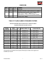
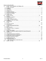
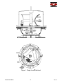
1
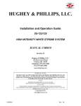
HU
UGH
HEY & PHIL
P LLIIPS, LLC
C.
Ins
stallatiion and Operation Guide
e
FL
LASHG
GUARD 2000B
FL
LASHG
GUARD 3000B
12
20/240//480, 50
0/60HZ
MED
DIUM INTE
ENSITY WHITE,
W
R
RED
AND DUAL LIIGHTING SYSTEM
MS
E
EPM-00
000000
02-001
Re
evision D
Hughey
y & Phillips, LLC.
L
136 Ea
ast Court Stre
eet
Urban
na, OH 4307
78
Telephon
ne (937) 652--3500
Fax (9
937) 652-350
08
www.o
oblighting.co
om
PROPR
RIETARY NOTIC
CE
THIS DOCUM
MENT AND THE
E INFORMATION
N DISCLOSED HEREIN
H
ARE PR
ROPRIETARY DA
ATA OF
HUGHEY & PHILLIPS INC. NEITHER THIS
S DOCUMENT NOR
N
THE INFOR
RMATION CONT
TAINED
LL BE REPROD
DUCED, USED, OR
O DISCLOSED
D TO OTHERS WITHOUT
W
THE WRITTEN
W
HEREIN SHAL
AUT
THORIZATION OF
O HUGHEY & PHILLIPS
P
INC.
NOTICE
FREE
EDOM OF INFOR
RMATION ACT (5 USC 552) AND
D
DISCLOSU
URE OF CONFID
DENCE INFORM
MATION GENER
RALLY
(18 USC 1905)
THIS DO
OCUMENT IS BE
EING FURNISHE
ED IN CONFIDEN
NCE BY HUGHE
EY & PHILLIPS INC.
THE INFORMA
ATION DISCLOSED HEREIN FAL
LLS WITHIN EXE
EMPTION (b) (4) OF 5 USC 552 AND THE
PROHIBITIO
ONS OF 18 USC
C 1905.
Copyright 2010
2
Honeyw
well Inc.
All Rig
ghts Reserve
ed
EPM-00000002-001
Rev. D
REV
VISIONS
S
REV
DATE
ECO
COMMEN
NT
A
4/21/04
3871
Initial Issu
ue
B
5/14/04
4242
Add spare
e Flashhead o-rings to
o spare parts list, page
e 48.
C
9/17/08
Updated document
d
f
formatting,
table of con
ntent, list off
figures, Figure 3, Fig
gure 6, Add
ded Figure 9 -13,
Updated Section
S
7.0
0 Part List, GPS
G
system
m installatio
on
D
4/1/10
Companyy Name Cha
ange
TABLE OF FLA
ASH GUA
ARD ST
TANDAR
RD SYST
TEMS
FG2000B
B SYSTEMS ARE
A
SINGLE
E RED NIGHT
T ONLY OR WHITE
W
DAY/N
NIGHT
FG3000B
B SYSTEMS ARE DUAL NIGHT
N
AND DAY
MODEL
R
NUMBER
IN
NPUT
VOL
LTAGE
Hz.
PO
OWER SUP
PPLY P/N
F
FG2000B-00
04
120/240VAC
60
40000681-023
*277-5047
7W (white)
F
FG2001B-00
04
240/4
480VAC
50
40000681-021
*277-5047
7W (white)
F
FG2002B-00
04
240/4
480VAC
60
40000681-024
*277-5047
7W (white)
F
FG2006B-00
04
240/4
480VAC
50
40000681-021
*277-5047
7R (red)
F
FG2007B-00
04
240/4
480VAC
60
40000681-024
*277-5047
7R (red)
F
FG2009B-00
04
120/240VAC
60
40000681-027
*277-5047
7R (red)
F
FG3000B-00
04
120/240VAC
60
40000681-033
*277-5004
4RW (red and
a white)
F
FG3001B-00
04
240/4
480VAC
50
40000681-031
*277-5004
4RW (red and
a white)
F
FG3002B-00
04
240/4
480VAC
60
40000681-034
*277-5004
4RW (red and
a white)
F
FG3004B-00
04
240/4
480VAC
60
40000681-035
*277-5004
4RW (red and
a white)
F
FG3005B-00
04
240/4
480VAC
50
40000681-032
*277-5004
4RW (red and
a white)
FLA
ASH HEAD P/N
This manuall covers the
T
e above listed systemss. Manual(ss) for otherss custom syystems are
available upon request.
EPM00000002
2-001
i
Rev. D
TABLE OF CONTENTS
T
C
S
1.0 SAFE
ETY AND GENERAL
G
INFORMAT
TION ............................................................... 4 1.1 1.2 1.3 1.4 1.5 1.6 1.7 1.8 1.9 Equipm
ment Descripttion ....................................................................................................................................... 4 Flashh
heads ........................................................................................................................................................ 4 Powerr Supply ..................................................................................................................................................... 4 Safetyy Notice ...................................................................................................................................................... 8 Safetyy Summary ................................................................................................................................................ 9 Electro
ostatic Discha
arge ...................................................................................................................................... 9 Powerr Tools and Hand Tools .......................................................................................................................... 10 Mainte
enance Philos
sophy .................................................................................................................................. 10 Refere
ence Data ................................................................................................................................................ 12 2.1 2.2 2.3 2.4 2.5 2.6 Unpaccking ........................................................................................................................................................ 14 Mounting and Prepa
aration................................................................................................................................ 14 Installa
ation Wiring............................................................................................................................................. 19 GPS Sync
S
Wiring (O
OPTIONAL) ....................................................................................................................... 20 GPS Sync
S
Installation (OPTIONA
AL) ................................................................................................................ 20 Final Check
C
...................................................................................................................................................... 27 2.0 3.0 INSTA
ALLATION ...................................................................................................... 14 OPER
RATION ........................................................................................................... 28 3.1 Generral ............................................................................................................................................................ 28 3.2 Operating Procedurres ...................................................................................................................................... 28 3.3 Statuss Indicators .............................................................................................................................................. 28 4.0 FUNC
CTIONAL DESCRIPTI
D
ION................................................................................ 30 4.1 4.2 4.3 4.4 4.5 Generral ............................................................................................................................................................ 30 Major Assemblies
A
............................................................................................................................................. 30 Functio
onal Descripttion of Subsysstems............................................................................................................. 30 GPS SYNC
S
...................................................................................................................................................... 37 System
m Failure (Ala
arms) .................................................................................................................................. 37 5.1 5.2 5.3 5.4 5.5 5.6 5.7 5.8 5.9 5.10 Generral ............................................................................................................................................................ 39 Tools Required ................................................................................................................................................. 39 Troubleshooting Pro
ocedures and
d Tables ......................................................................................................... 39 ............................................................................ 40 Flashh
head (Strobe)) Problems Lo
ogic Diagram.....................
.
Multiplle Strobe Problems Logic Diagram
D
........................................................................................................ 45 Side Light
L
Problems
s Logic Diagrram ................................................................................................................ 47 Flashh
head Isolation
n Test .................................................................................................................................. 48 Powerr Supply Isola
ation Test ............................................................................................................................ 49 Flashh
head Maintenance................................................................................................................................... 50 Pow
wer Supply an
nd Light Senssor Maintenan
nce ........................................................................................... 52 5.0 6.0 TROU
UBLESHOO
OTING AND
D CORREC
CTIVE MAINTENANCE ................................ 39 PART
TS LISTING
G ..................................................................................................... 53 EPM00000002
2-001
ii
Rev. D
LIST OF
O FIGUR
RES
FIGURE 1. SINGLE LE
F
EVEL FLAS
SHHEAD ......................................................................... 6 F
FIGURE
2. DUAL LEV
VEL FLASH
HHEAD ............................................................................. 7 F
FIGURE
3. LIGHTING
G SYSTEM POWER SUPPLY ........................................................... 8 F
FIGURE
4. SINGLE LE
EVEL FLAS
SHHEAD OUTLINE
O
DRAWING ..................................... 16 F
FIGURE
5. DUAL LEV
VEL FLASH
HHEAD OUT
TLINE DRA
AWING ........................................ 17 F
FIGURE
6. LIGHTING
G SYSTEM POWER SUPPLY OU
UTLINE DRAWING ...................... 18 F
FIGURE
7. SYSTEM
S
WIRING
W
DIA
AGRAM ......................................................................... 22 F
FIGURE
8. SYSTEM WIRING
W
DIA
AGRAM FO
OR MASTE
ER / SLAVE
E UNITS ...................... 23 F
FIGURE
9. SYSTEM
S
WIRING
W
DIA
AGRAM FO
OR UNIT WITH
W
GPS ..................................... 23
F
FIGURE
10.. INTERNA
AL WIRING DIAGRAM FOR UNIT
T WITH GPS ................................ 24
F
FIGURE
11.. GPS FLAS
SH RATE DIP
D SWITC
CH POSITIO
ONS ............................................. 25
F
FIGURE
12.. GPS POLE MOUNT (OPTIONA
AL) ................................................................ 26
F
FIGURE
13.. GPS UNIT
T (OPTIONAL) ............................................................................... 27
F
FIGURE
14.. FG3000B LIGHTING
G SYSTEM SCHEMAT
TIC DIAGRA
AM.............................. 32 F
FIGURE
15.. FG2000B LIGHTING
G SYSTEM SCHEMAT
TIC DIAGRA
AM.............................. 33 F
FIGURE
16.. FG3000B TRIGGER CONTROL
L SWITCH SETTINGS
S ................................. 35 F
FIGURE
17.. FG2000B TRIGGER CONTROL
L SWITCH SETTINGS
S ................................. 35 F
FIGURE
18.. FG2009B TRIGGER CONTROL
L SWITCH SETTINGS
S ................................. 35 F
FIGURE
19.. SYNC/MO
ONITOR SW
WITCH SET
TTINGS ........................................................ 36 F
FIGURE
20.. FG3000B SYNC/MO
ONITOR SW
WITCH SET
TTINGS ........................................ 37 F
FIGURE
21.. FG2000B SYNC/MO
ONITOR SW
WITCH SET
TTINGS ........................................ 37 F
FIGURE
22.. FG2009B SYNC/MO
ONITOR SW
WITCH SET
TTINGS ........................................ 37 F
FIGURE
23.. GPS SYNC SWITCH
H SETTING
GS .................................................................. 38
F
FIGURE
24.. FLASHTU
UBE ASSEM
MBLY WITH
H FERRITE
E BEADS ..................................... 52
F
FIGURE
25.. ATTACHM
MENT OF FERRITE
F
B
BEADS
WIT
TH QUICK--ON CONN
NECTIONS . 52 F
FIGURE
26.. FLASHTU
UBE INSER
RTION............................................................................ 53 LIST OF
O TABL
LES
TABLE 1.
T
T
TABLE
2.
T
TABLE
3.
T
TABLE
4.
T
TABLE
5.
T
TABLE
6.
T
TABLE
7.
T
TABLE
8.
LIMITATION
L
NS OF MAINTENANC
CE .................................................................. 11 M
MAINTENAN
NCE WORK REQUIR
REMENTS ..................................................... 11 E
EQUIPMEN
T SPECIFICATIONS ..................................................................... 12 L
LED
STATU
US INDICAT
TORS ............................................................................ 29 S
SIDE
LIGHT
T ALARM MODULE
M
FA
AULT INDICATORS..................................... 38 F
FLASHHEA
AD (STROBE) PROBLEMS CORR
RECTIVE MAINTENA
M
ANCE.......... 41 M
MULTIPLE
STROBE
S
P
PROBLEMS
S CORREC
CTIVE MAIN
NTENANCE
E ................ 46 S
SIDE
LIGHT
T PROBLEM
MS CORRE
ECTIVE MA
AINTENANCE ............................. 47 EPM00000002
2-001
iii
Rev. D
1.0
SAFETY AND
D GENERA
AL INFOR
RMATION
N
1.1 Equipment Des
scription
pacitor disccharge, xen
non flash strobe light system
s
The liighting systtem is a cap
manu
ufactured to
o comply with Federal Aviation Ad
dministratio
on (FAA) Ad
dvisory Circcular
150/5
5345-43E. Each
E
system
m consists of an omni-directionall flashhead, associated power
supply with integ
grated controls, ambie
ent light sen
nsor (photoccell), and an interconn
necting
cable
e. System componentss are shown
n in Figuress 1, 2 and 3.
3 Modificatiions may be made
to suit different applications
a
s.
1.2 Flash
hheads
1.2.1 Single Le
evel (Red orr Clear)
The flashhead, Figure 1, consissts of one acrylic
a
lens assembly (red
(
or clea
ar)
d base. Included within
n the flashh
head is the flashtube
attached to a hinged
y, an interlock switch, trigger
t
transsformer and the termin
nal block where
w
the
assembly
interconnecting cable terminate
es.
el (Red and
d Clear)
1.2.2 Dual Leve
The flashhead, Figure 2, consissts of two acrylic
a
lens assembliess (red and clear)
c
attached to a hinged
d base. Included within
n the flashh
head are the
e two flashttube
assemblie
es (one for the red and
d one for th
he white), an interlock switch, two
o trigger
transform
mer and the terminal block where the interconnecting ca
able termina
ates.
er Supply
1.3 Powe
The power
p
supp
ply contains power con
ntrol circuitss (relays, fu
uses, switch
hes) for both strobe
and auxiliary
a
sid
de lights, a high-voltag
h
e circuit (po
ower transfformer, recttifiers, enerrgy
storag
ge capacito
ors, discharrge circuits)), flash interval and tim
ming circuitss, dual mon
nitor
circuits, intensity
y selection controls, an
nd a triggerr generator. Also attacched to (or remotely
r
locate
ed from) the
e power supply is the ambient light sensor (photocell).
Optio
onal items may
m include
e a Power Line
L
Filter and/or
a
alarm
m lockout module
m
(K6-K7)
depen
nding on re
equired systtem. Modifications ma
ay be made to suit diffe
erent appliccations.
EPM00000002
2-001
4
Rev. D
Figure 1. Single Level Flashhead
EPM00000002
2-001
5
Rev. D
Fig
gure 2. Du
ual Level Flashhead
EPM00000002
2-001
6
Rev. D
Figure 3. Lighting System Power Sup
pply
(su
upplied powerr supply may be
b different)
EPM00000002
2-001
7
Rev. D
1.4 Safety Notice
1.4.1 Voltages
The Indiv
vidual contro
ol cabinet contains
c
voltages of 1,000 VDC and
a constitu
utes a
personne
el safety hazzard. Perso
onnel must observe sa
afety regula
ations at all times.
1.4.2 Interlocks
s
The Indiv
vidual Contrrol Cabinet contains in
nterlocks forr your prote
ection. To ensure
e
safety, alw
ways removve power frrom the equ
uipment prior to opening any acccess
panel or door.
d
Do no
ot depend on
o the interllocks or door switchess for person
nnel
protection
n when worrking with th
he equipme
ent. Do not short-circuit or tamper with
any acces
ss gate, door, or otherr safety inte
erlock switcch. Ground capacitors with a
grounding
g rod prior to
t touching any compo
onent. Whe
en it is abso
olutely mandatory
that an interlock be bypassed
b
in
n order to trace a faultt or correct a malfunction
authorized maintena
ance person
nnel may pe
erform the bypass for the specificc test to
be perform
med.
1.4.3 Keep Awa
ay From Livve Circuits
Operating
g and mainttenance pe
ersonnel mu
ust observe
e all safety regulations
r
at all
times. Do
o not change “Plug-In” componen
nts or make adjustmen
nts inside th
he
equipmen
nt with the high
h
voltage
e power control circuitts in the ON
N position. Under
U
certain co
onditions, dangerous voltage
v
pote
entials mayy exist in cirrcuits with the
Power Co
ontrols in th
he OFF possition due to
o the charge
es retained
d by the flassh
capacitors
s. To avoid
d casualtiess, always re
emove the power,
p
wait one (1) minute,
and then discharge the
t flash ca
apacitors, C1,
C C2, and
d C3, by tou
uching a gro
ounding
rod to the
e capacitor terminals,
t
p
prior
to toucching any component.
c
.
1.4.4 Resuscita
ation
Maintenance person
nnel shall fa
amiliarize th
hemselves with
w the tecchnique for
o First Aid Instruction
ns.
resuscitattion found in manual on
onary Notice
e for Semicconductor and
a Integratted Circuitss
1.4.5 Precautio
This equipment conttains semicconductor devices / inttegrated circuits. Take
e the
necessary
y ESD preccautions priior to attem
mpting any service
s
work.
EPM00000002
2-001
8
Rev. D
1.5 Safety Summarry
The following
f
is
s a summarry of warnin
ngs containe
ed within th
his technica
al manual:
W
WARNING!
!
Thiis system us
ses lethal volltages in botth the powerr supply
and
d the flashhe
ead. Do not attempt
a
to se
ervice or adju
ust the
equ
uipment with
h line power applied.
Inte
erlock switch
hes are prov
vided in both
h the flashhea
ad and
pow
wer supply enclosures
e
to
o interrupt main
m
power to
o the
pow
wer supply. These switch
hes are activ
vated when the
t power
sup
pply door orr flashhead le
ens assemblly is opened in a
con
nventional manner.
m
No in
nterlock is prrovided whe
en other
me
eans of acces
ss are used. Never tampe
er with (remo
ove, short
circ
cuit) the inte
erlocks in any
y way.
W
WARNING
Lin
ne voltage is still presentt when interlo
ocks are acttivated.
Dis
sconnect pow
wer before in
nspecting orr servicing
W
WARNING
Ens
sure that the
e power is OF
FF and the capacitor
c
ban
nk has
bee
en discharge
ed before op
pening the fla
ashhead.
W
WARNING
Ins
stalling contrrol boards th
hat are incorrrectly config
gured may
cau
use damage and system failure.
W
WARNING
Letthal voltages
s are presentt in the cond
ductors betw
ween the
pow
wer supply and
a flashhea
ad. There sho
ould be one continuous
c
run
n of cable fro
om flashhead
d to power su
upply. Underr no
circ
cumstance should
s
these
e conductors
s be spliced.
1.6 Electtrostatic Dis
scharge
The componentts inside yo
our system are
a extremely sensitivve to static electricity,
e
a
also
know
wn as electrrostatic disccharge (ES
SD). Static electricity
e
ca
an cause irrreparable damage
d
to yo
our system; however, if you follow
w these prevventative measures
m
and precautiions, you
shou
uld prevent such dama
age.
a)
Static Ele
ectricity Prevention:
EPM00000002
2-001
9
Rev. D
b)
1.
We
ear a groun
nding wrist strap
s
(available at mosst electronic stores).
2.
Turn off the system pow
wer.
3.
Un
nplug all corrds from the
e wall outle
et.
4.
Re
emove the case
c
cover..
Static Ele
ectricity Precautions:
1.
If you're
y
repla
acing or add
ding parts, remove the
e parts from
m their antisstatic
bags only when you are ready to usse them. Do not lay pa
arts on the outside
of antistatic bags since only
o
the insside provide
es antistaticc protection.
2.
Av
void static-ccausing surffaces, such
h as plastic and Styroffoam in you
ur work
are
ea.
3.
Alw
ways hold cards
c
by the
eir edges and
a their me
etal mountin
ng bracket. Avoid
tou
uching com
mponents on
n the cards and the ed
dge connectors that co
onnect to
expansion slo
ots.
4.
Ne
ever slide ca
ards or othe
er parts ove
er any surfa
ace.
1.7 Powe
er Tools an
nd Hand To
ools
Prop
per safety procedures shall
s
be observed whe
en using po
ower tools or
o hand tools.
1.8 Main
ntenance Ph
hilosophy
Docu
umentation reflects ma
aintenance philosophyy and suppo
orts equipm
ment to this extent.
Funcctional theo
ory of opera
ation and flo
ow-charts fo
or field troubleshooting
g support field
main
ntenance. Parts
P
listing reflect onlyy items thatt can be rem
moved or re
eplaced by field
main
ntenance pe
ersonnel. Parts
P
and co
omponents that are no
ot suited forr field repairr or
repla
acement are
e not includ
ded in the te
echnical ma
anual.
Refe
er to Table 1 for a desccription of th
he limitation
n of mainte
enance.
Refe
er to Table 2 for mainte
enance worrk requirem
ments and established
e
limitations for field
and supplier.
s
EPM00000002
2-001
10
Rev. D
Table
e 1. Limita
ations of Maintenanc
M
ce
Field
•
Periodic check
ks of equipme
ent
Performance.
•
V
Visual
inspections
•
C
Cleaning
of system elements
•
Servicing of sp
pecified itemss
•
Assembly/suba
A
assembly rem
moval and
re
eplacement.
•
Scheduled maintenance req
quiring
eq
quipment disa
assembly and
d assembly
(liimited to majo
or assembliess and
su
ubassemblies
s).
S
Supplier
Comple
ete overhaul, rebuilding, an
nd
perform
mance testing of assemblie
es,
subassemblies, and component replacement.
r
Note::
Field maintenance is limited to removal
r
and replacement
r
of the followin
ng items:
M
assembllies
• Major
• Predetermined
d subassembllies
d circuit card assemblies
a
• Predetermined
• Fuses
nterconnecting
g cables
• In
• Bulbs
ens covers
• Le
Table 2.. Maintena
ance Work Requirem
ments
Crite
eria
Field Maintenance
Supplier Main
ntenance
Done
e where?
At the operational siite or where
ever
the prime
e equipmen
nt is located
d.
Specialized re
epair activity
or manufactur
m
rer’s plant.
Done
e by
whom
m?
System/e
equipment operating
o
personne
el.
Supplier facilitty personne
el
or manufactur
m
rer’s
pro
oduction personnel.
On whose
w
equip
pment?
Using org
ganization’ss system.
Equivalent Ho
oneywell
sysstem.
Type
e of work
Visual insspection
acco
omplished? Operation
nal checkou
ut
Minor serrvicing
External adjustment
a
ts
Removal and replaccement of some
s
compone
ents.
EPM00000002
2-001
11
Complicated factory
f
adjjustments.
Complex equiipment
rep
pair and mo
odifications..
Ovverhaul and rebuild
Detailed calibration
ntenance
Sofftware main
(de
etailed modifications).
Supply suppo
ort
Rev. D
1.9 Refe
erence Data
a
Referr to Table 3 for a listing
g of the equ
uipment spe
ecificationss.
Table 3. Equip
pment Spe
ecifications
s
Item
Specifica
ation
Light Outtput
Day Intensity
20,0
000 ±25% effe
ective candela
as, single flassh
Nightt Intensity
2,00
00 ±25% effecctive candelass, burst of flasshes
Beam
m Pattern
360ºº horizontally; 3º min. verticcally; Maximu
um intensity of
o 3% of peak @ –10°
Flash
h Rate
Da
ay
40 flashes per minute (FPM) - single white flash
f
Nig
ght
20–4
40 FPM red flash burst
Maste
er/Slave Operation
Up to
o 4 slave unitts may share a common syync and photo
ocell circuit
Side Lights
1 to 4 type L-810 lights steadyy burn night on
nly
Electrical Input
I
Powe
er Supply
120, 240, 480 VA
AC 50 or 60 Hz
Side Lights
1 to 4 type L-810,, 120V LED or
o 116 W, 120
0 V incandesccent
Me
echanical Prroperties
Flash
hhead
We
eight
34 pounds
p
Dim
mensions (inc
ches)
16.5
5 wide X 23 hiigh
Su
urface area
1.98
8 ft/2
Wind Load
105 pounds @ 15
50 mph
Powe
er Supply
We
eight
65 pounds
p
Dim
mensions (inc
ches)
21 wide
w
X 16.5 hiigh 10.5 deep
p
Op
perating Environment
Temp
perature
–55ººC to +55ºC
Humiidity
95%
% relative
Status Indic
cators
Neon
n Lamps
Pow
wer line and hiigh voltage indicators
LED
Sync//Monitor PCB
B
Syncc out, master (red); fault re
elay (green)
Trigger Control PC
CB
Syncc line active (g
green); red LED on (red)
Fault
Strrobe
Rela
ay closure, co
ontact ratings 3 A @ 120 VAC
V
Inccandescent/LED
Rela
ay closure(s), contact rating
gs 3 A @ 120
0 VAC
EPM00000002
2-001
12
Rev. D
Item
Specificattion
Electrical input
GPS
Inp
put Power
Fla
ash Rate Settings
Day
Nite
Nite Enable Input
I
Ca
able Length (fe
eet)
100–132 VAC/ 50 or 60 Hz, 10 watts Max
F
40 FPM
24, 30, 40, 60 FP
PM
100–132 VAC/ 50-60 Hz
25, 50, 100, 150,, 350 available
Mec
chanical Pro
operties
We
eight
Dim
mensions (inc
ches)
3.6 pounds
7.37
74 wide X 6.2
25 high
Ope
erating Environment
Tem
mperature
Humidity
–40ºC to +55ºC
95%
% relative
S
Status
Indica
ators
LED
G
Green
Y
Yellow
R (Flashing
Red
g)
EPM00000002
2-001
wer On
Pow
GPS
S Lock
Syn
nc
13
Rev. D
2
2.0
INST
TALLATIO
ON
2.1 Unpa
acking
Care
efully unpac
ck each item
m and remo
ove any inte
ernal packin
ng material from the power
supp
ply and flash
hhead. Exa
amine each item for ob
bvious physsical damag
ge. Report any
a
claim
ms to the ca
arrier immed
diately. Perrtinent data such as installation drawings,
sche
ematics, inte
erconnectio
on drawingss, and operration manu
uals are included in the
e power
supp
ply carton. The
T flashtub
be is packa
aged inside the flashhe
ead.
2.2 Moun
nting and Preparation
P
2.2.1 General
Th
his section contains
c
de
etailed draw
wings for mo
ounting the flashhead and
power supplyy. See Figurres 4, 5 and
d 6.
S
Flasshhead
2.2.2 Lighting System
No
ormally the flashhead is
i mounted at the uppermost poin
nt on the sttructure.
It must
m
be mo
ounted leve
el to assure proper ligh
ht output.
2.2
2.2.1
Insta
allation Reccommendations for AM
M Towers
Fo
or AM towerrs, an isolattion device must be ussed for the tower lighting
sys
stem. There
e are three options avvailable: Iso
olation transsformer, tow
wer
ligh
hting choke
es, and cusstom isolatio
on inductors.
Fo
or mechaniccal incandescent red lighting conttrols, isolatiion transforrmers
and tower ligh
hting choke
es provide a reliable means
m
of supplying AC
C power
wers, an isolation transsformer
to the tower liighting conttrol. For some AM tow
ay be the be
etter choice
e as they prrovide high RF impeda
ance betwe
een
ma
tow
wer and gro
ound. With either of the
ese devices, the tower lighting co
ontrol is
mo
ounted to th
he tower. If possible, th
he lighting control sho
ould not be located
at a high RF current
c
poin
nt. Isolation
n transforme
ers and tow
wer lighting chokes
are
e not recom
mmended fo
or solid-statte red lighting controlss or for strob
be
ligh
hting system
ms.
Cu
ustom isolattion inducto
ors are the preferred choice
c
for so
olid-state re
ed
ligh
hting contro
ols and stro
obe lighting systems. Custom
C
isolation inducctors
pro
ovide isolattion betwee
en the tower lighting co
ontrol/powe
er supply an
nd the
tow
wer lighting fixtures. The conducttors betwee
en the tower lighting fixxtures
and the lightin
ng controls are would through a copper
c
indu
uctor, allowing the
ligh
hting contro
ol/power su
upply to be mounted att ground po
otential. Use
e of the
Cu
ustom Isolattion Inducto
or provides several ad
dvantages: The lighting
g
controls or strrobe powerr supplies are
a kept outt of the RF field,
f
and can
c be
orked on witthout shuttiing down th
he transmittter. Also, th
he lighting alarm
a
wo
contacts are easily
e
available for rem
mote monito
oring.
EPM00000002
2-001
14
Rev. D
Figure 4. Single Leve
el Flashhea
ad Outline Drawing
EPM00000002
2-001
15
Rev. D
Figure 5. Dual Level Flashhead
d Outline Drawing
EPM00000002
2-001
16
Rev. D
HUGHEY & PHILLIPS
Figurre 6. Lighting System
m Power Supply Outlline Drawin
ng
EPM00000002
2-001
17
Rev. D
Fo
or any lightin
ng system on
o AM towe
ers, the ligh
hting condu
uctors or ca
ables
sho
ould be installed in ga
alvanized stteel conduitt. The cond
duit system should
be bonded to each towe
er section with
w a bondin
ng strap. If the tower is
painted, the paint
p
should
d be scrape
ed off before
e installing the bonding kits.
Aftter pulling the wires through the conduit
c
system, an inssulation testt using a
me
egger should be performed betwe
een every conductor-t
c
o-conducto
or, and
between everry conducto
or-to-conduit system. Installation Recommen
ndations
forr FM towerss:
ARNING
WA
Lethal volttages are pre
esent in the conductors
c
b
between
the power supply and
flashhead.
f
Th
here should be one contiinuous run of
o cable from
m flashhead to
t power
supply
y. Under no circumstance
c
e should the
ese conducto
ors be spliced.
Fo
or strobe lighting systems on FM towers,
t
carre should be
e taken nott to
expose strobe
e cable to high
h
FM RF
F fields. Gen
nerally this is done by running
e strobe cab
ble in conduit through the aperture of the FM
M antenna. Conduit
the
sho
ould be installed from 15 feet bellow the botttom bay of the FM anttenna to
15 feet above
e the top ba
ay. The conduit should
d be bonded
d to the tow
wer using
a bonding
b
kit every 5 fee
et. If the tow
wer is painted, the pain
nt should be
scrraped off be
efore installing the bon
nding kit.
2.2.3 Lighting System
S
Pow
wer Supply
Th
he power su
upply is con
nnected to its flashhea
ad via the ca
able provided by
Ho
oneywell. Th
he length of
o this cable
e determine
es how far frrom the flasshhead
the
e power sup
pply can be
e mounted.
Th
he user should determine that the
e power line
e voltage se
elector, loca
ated on
the
e transformer board inside the po
ower supplyy enclosure is set to th
he main
voltage being
g used.
L
Senso
or
2.2.4 Ambient Light
Th
he ambient light sensor, when sup
pplied with the system
m, should be
e
mo
ounted upright, away from
f
artificia
al light (e.g., floodlightts), and in a
loc
cation that will
w enable its sensor window
w
to have
h
an uno
obstructed view of
the
e polar sky (e.g., pointted north in the Northe
ern Hemisphere). Typ
pical
ins
stallation is done by ussing ½” rigid
d conduit and #14-AW
WG wire to remotely
r
mo
ount the photocell.
EPM00000002
2-001
18
Rev. D
2.3 Insta
allation Wiring
Perfo
orm the following proccedures for installing in
nterconnectting wiring (see
(
Figure
e 7 for
stand
d-alone installation and Figure 8 for master//slave insta
allation):
a) Conne
ect all wiring between the flashhe
ead and the
e power sup
pply using
Honey
ywell suppliied cable P/N
P *77-4017-4. The wires
w
in this cable are color
c
coded
d and conne
ect to the numbered te
erminals of flashhead TB1
T
corressponding
numbe
ered termin
nals of the power
p
supp
ply TB2.
b) Conne
ect all wiring that intercconnects between the
e steady burning red side lights
and po
ower supplyy using the
e Honeywell supplied cable
c
WC23
3012CL0T or
WC23
3012DL0T or
o equivalen
nt #12 AWG
G cord (colo
or coding may
m be diffe
erent
than liisted below
w). The wire
es in this cable are con
nnected to the
t numberred
termin
nals of TB1 as follows::
1. Black Wire
e of Cable to
t TB1-11, 120VAC Liine out to Sidelight
S
Level 1
2. Orange Wire
W of Cable to TB1-12
2, 120VAC Line out to
o Sidelight Level
L
2
3. Red Wire of Cable to
o TB1-10, Neutral
N
return from Sid
delight Leve
el(s)
4. Blue Wire of Cable to
o TB1-Grou
und Lug
c) Conne
ect wiring between
b
the
e external photocell
p
an
nd the powe
er supply ussing #12
AWG wire. The wires
w
in thiss cable are connected from TB1, as follows:
1. Black wire
e of the pho
otocell to TB
B1-2
2. Red wire of
o the photo
ocell to TB1
1-1
3. White wire
e of the pho
otocell to TB
B1-Ground lug
he wiring be
etween the master
d) For structures with 2 or morre systems,, connect th
powerr supply and
d slave pow
wer supply using Hone
eywell cable
e *77-4231. This
cable has a total of 10 cond
ductors and can be use
ed to distrib
bute power and
timing
g pulses and
d consolida
ates alarm functions
f
to
o and from slave
s
powe
er
supplies. For dettails consultt Honeywelll Tech Sup
pport at 805
5-581-5593.
EPM00000002
2-001
19
Rev. D
2.4 GPS
S Sync Wirin
ng (OPTION
NAL)
Perfo
orm the following proccedures for installing in
nterconnectting wiring (see
(
Figure
e 9 for
Syste
em installattion and Fig
gure 10 for Power Sup
pply interna
al GPS wirin
ng installation):
a) Conne
ect all wiring between the flashhe
ead and the
e power sup
pply using
Honey
ywell suppliied cable P/N
P *77-4017-4. The wires
w
in this cable are color
c
coded
d and conne
ect to the numbered te
erminals of flashhead TB1
T
corressponding
numbe
ered termin
nals of the power
p
supp
ply TB2.
b) Conne
ect all wiring that intercconnects between the
e steady burning red side lights
and po
ower supplyy using the
e Honeywell supplied cable
c
WC23
3012CL0T or
WC23
3012DL0T or
o equivalen
nt #12 AWG
G cord (colo
or coding may
m be diffe
erent
than liisted below
w). The wire
es in this cable are con
nnected to the
t numberred
termin
nals of TB1 as follows::
1. Black Wire
e of Cable to
t TB1-11, 120VAC Liine out to Sidelight
S
Level 1
2. Orange Wire
W of Cable to TB1-12
2, 120VAC Line out to
o Sidelight Level
L
2
3. Red Wire of Cable to
o TB1-10, Neutral
N
return from Sid
delight Leve
el(s)
4. Blue Wire of Cable to
o TB1-Grou
und Lug
c) Conne
ect all wiring between the GPS Sync
S
and the
e power supply using
Honey
ywell suppliied cable P/N
P 4000207
74-( ) for GPS
G
connecctor location
n (see
Figure
e 6).
2.5 GPS
S Sync Insta
allation (OP
PTIONAL)
The GPS (part number 400
002075) un
nit should be mounted outdoors with
w a clear view of
the South
S
sky. A 25 to 350
0-feet GPS cable can be
b ordered as needed
d. Nearby
obstrructions to the South should
s
be avoided.
a
Th
he unit shou
uld be moun
nted on a flat
verticcal surface or a pole (ssee Figure 12).
h S1-4 on th
he Sync/Mo
onitor Boarrd should be
e in the ON
N (slave) po
osition for
a) Switch
all GP
PS-controlle
ed units.
b) Typica
ally requiress one of the
e following photocells (sold separrately). Imp
portant: If
photoc
cell is not re
equired, so
ocket cover must be left in place to
t prevent water
w
entry into
i
GPS unit.
1. Photocell 77-3258-00
01 (for Red Beacons, 35–58 fc)
2. Photocell 77-3759-00
01 (for Whitte or Dual Beacons,
B
1–3 fc)
EPM00000002
2-001
20
Rev. D
W
WARNING
Lethal high
h
voltages are present in the
e conducto
ors betwee
en the
pow
wer supply
y and the fllashhead. There should be one
e
continuo
ous run of cable from
m flashhea
ad to power supply. Under
U
no circumstan
c
nces shoulld these co
onductors be spliced
d.
Fig
gure 7. Sys
stem Wiring
g Diagram
EPM00000002
2-001
21
Rev. D
W
WARNING
Lethal high
h
voltages are present in the
e conducto
ors betwee
en the
pow
wer supply
y and the fllashhead. There should be one
e
continuo
ous run of cable from
m flashhea
ad to power supply. Under
U
no circumstan
c
nces shoulld these co
onductors be spliced
d.
Figurre 8. Syste
em Wiring Diagram fo
or Master / Slave Uniits
EPM00000002
2-001
22
Rev. D
Fig
gure 9. Sys
stem Wirin
ng Diagram
m for Units with GPS
EPM00000002
2-001
23
Rev. D
Fig
gure 10. In
nternal Wiriing Diagra
am for Unit with GPS
EPM00000002
2-001
24
Rev. D
Figure 11. GPS Flash
h Rate Dip
p Switch Po
ositions
EPM00000002
2-001
25
Rev. D
Figure
e 12. GPS Pole Mount (Optional)
EPM00000002
2-001
26
Rev. D
Figure 13. GPS
G
Unit (O
Optional)
2.6 Finall Check
Before applying
g power to the
t equipment, check all relays and
a printed circuit boarrds
(PCB
Bs) to ensure that theyy are properly seated in
i their sockets. Checkk to ensure
e that any
user--installed wiring
w
does not interferre with relayy operation when cove
ers are clossed.
EPM00000002
2-001
27
Rev. D
3
3.0
OPE
ERATION
3.1 Gene
eral
This section pro
ovides inforrmation for operating the lighting system durring normall
operating conditions.
3.2 Operrating Proce
edures
Afterr the system
m has been wired acco
ording to the instructio
ons in Sectio
on 3, it is re
eady for
norm
mal operatio
on. The flasshhead asse
embly shou
uld be close
ed and secu
ured. When
n the
cove
er of the pow
wer supply is closed so that the in
nterlock sw
witch is enga
aged and power
p
is
appliied, the sys
stem will be
egin to operrate. If there
e is sufficient light and
d the ambient light
senssor is mounted correctly, the syste
em will auto
omatically switch
s
to the correct mode
m
after a 1 to 2 minute delay. The delayy protects against
a
unw
warranted sw
witching du
ue to
mom
mentary cha
anges in the
e light reach
hing the sen
nsor. If a GPS
G
sync un
nit is used the
t GPS
syncc indicator should
s
begin flashing at
a power-up
p, but allow 20 minutess for full syn
nc
operation. The built-in ante
enna requirres clear vie
ew of the so
outh horizo
on (in the no
orthern
p to 5 degre
ees elevatio
on (position the antenn
na straight up).
u
hemiisphere) up
3.3 Statu
us Indicatorrs
Refe
er to Table 4 LED statu
us indicatorrs.
EPM00000002
2-001
28
Rev. D
Ta
able 4. LED
D Status In
ndicators
Indic
cator
D
Description
n
C
Control
pow
wer ON
Located on the contrrol panel (top
p center), this
indicator is illuminate
ed wheneverr input powe
er is
present and
a the power supply intterlock switcch is
engaged.
H
High
Voltage
e Neon Lam
mp
Located on the high voltage circu
uit (top) board, this
lamp indiicates that th
he high volta
age circuits are
a
active.
ould be used if the neon lamp is
Extreme caution sho
on.
F
Flashhead
A
Alarm
Status
s LED
Located on the sync//monitor (middle) board,, this
LED will be green wh
hen the flash
hhead is ope
erating
correctly.
If the LED
D is off, the system is in alarm mode
e.
S
Sync
Out LE
ED
Located on the sync//monitor (middle) board,, this
LED blinkks red to ind
dicate that a sync signal has
been gen
nerated.
In a multiple flashhea
ad system, only
o
the
sync/mon
nitor board that is set ass the master will blink
this LED
S
Sync
In LED
D
Located on the trigge
er/control (bo
ottom) board
d, this
LED blinkks green to indicate thatt a sync sign
nal has
been recceived from the
t sync/monitor board.
F
Flashtube
Status LED
Located on the trigge
er/control (bo
ottom) board
d, this
LED is re
ed if the red flashtubes are
a in operattion.
If the whiite flashtube
es are being used, the LE
ED is
off.
S
Side
light Fa
ailure LED(s)
Located on the alarm
m card (AC) inside the lid
d of
power su
upply, these LEDs turn red to indicatte a side
light lamp
p failure.
This LED
D is green wh
hen the side
elights are op
perating
properly. LED2 will be
b lit RED du
uring night operation
ght level is in use.
when onlly one sidelig
Located on the botto
om of the GP
PS sync unit (Refer
to Figure
e 13), this LE
ED will turn green
g
when power is
on.
om of the GP
PS sync unit (Refer
Located on the botto
e 13), this LE
ED will turn yellow
y
when unit has
to Figure
locked on
nto a satellitte signal.
Located on the botto
om of the GP
PS sync unit (Refer
e 13), This LE
ED will flash
h red with ea
ach sync
to Figure
pulse.
G
GPS
SYNC Green LED
G
GPS
SYNC Yellow LED
D
G
GPS
SYNC Red LED
EPM00000002
2-001
29
Rev. D
4
4.0
FUNCTIONAL
L DESCR
RIPTION
4.1 Gene
eral
The purpose
p
of Section
S
5 iss to provide
e a general overall desscription of how the eq
quipment
comp
ponents function with relation
r
to each
e
other (equipment
(
t as a whole
e) and funcctional
descrription of ho
ow individua
al units or subassemb
s
blies of the equipment
e
function.
4.2 Majo
or Assemblies
The AC
A main po
ower input to the powe
er supply is converted to approxim
mately 1,00
00 VDC
to bia
as the flashttubes in the
e flashhead
d and to cha
arge the en
nergy storag
ge capacito
ors. The
ambie
ent light sen
nsor sends correct control signals to the pow
wer supply to automattically
chang
ge the inten
nsity of the flashhead and
a controll the red inccandescentt side lightss.
The main
m
powerr to the pow
wer supply is applied to
o the contro
ol and logicc circuitry, th
hereby
activa
ating relays
s that determ
mine the inttensity of th
he flashhea
ad. Logic cirrcuits in the
e power
supply generate a timing signal that co
ontrols the rate of flash. The GPS
S sync sign
nal
disab
bles the inte
ernal clock circuit.
c
The flash occurs at the sa
ame time ass the sync signal.
s
Test switch
s
located on the switch pane
el allows th
he system to
o operate in
n either dayy or
night mode. This
s switch sho
ould be leftt in the AUT
TO position for photocell operatio
on.
4.3 Funcctional Desc
cription of Subsystems
S
s
4.3.1 Lighting System
S
Flasshhead and
d Power Su
upply
Th
he main AC input powe
er is transfo
ormed to hig
gh voltage DC and sto
ored in
capacitors. Th
he trigger circuit
c
fires the
t flashtub
be, in paralllel with the
capacitors. Th
his discharg
ges the cap
pacitors, pro
oducing a flash
f
of light.
Ch
hanging the
e capacity fo
or energy stored
s
between flashess varies the
e
intensity of the light. The
e flashtube extinguishe
es when cu
urrent from the
t
t low to support
s
the arc. The power supplly short circcuit
capacitors is too
ube currentt to preventt continuouss
current is set below the minimum tu
T capacito
ors then reccharge for the
t next fla
ash.
conduction. The
put power iss applied to
o the primarry of the ferrroresonantt power tran
nsformer
Inp
(T1
1) when the
e flashhead
d and coverr interlocks are closed. The high voltage
v
output of T1 is rectified and
a charges the energ
gy storage capacitors.
c
In the day mo
ode, normall operation has the interlock relayy (K1) enerrgized
hile the day//night relayy K2 is de-e
energized. Capacitors
C
C2 and C3 in the
wh
hig
gh voltage circuit
c
are kept
k
charge
ed. With thiss amount off capacitance in the
circuit and DC
C voltage provided, su
ufficient ene
ergy is disch
harged thro
ough
shtube to produce
p
an effective in
ntensity of 20,000
2
cand
delas ( ±25%).
flas
In the night mode
m
(low in
ntensity), 12
20 VAC is supplied
s
fro
om the phottocell
o the power supply (on
n TB1-1) an
nd to the da
ay/night rela
ay (K2).
and applied to
Wh
hen K2 is energized,
e
itts contacts will remove
e C2 from the
t high-energy
circuit and disscharge it th
hrough R2 and R4. No
ow only C3, with R3 in
n series,
EPM00000002
2-001
30
Rev. D
is in
i the tube circuit. Thiss provides the
t energy required to
o produce th
he
efffective inten
nsity of app
proximately 2000 cand
delas. Conccurrently, 12
20 VAC
Figurre 14. FG30
000B Lightting System
m Schema
atic Diagram
EPM00000002
2-001
31
Rev. D
Figurre 15. FG20
000B Lightting System
m Schema
atic Diagram
EPM00000002
2-001
32
Rev. D
is applied
a
to pin
p 8 of the trigger con
ntrol PCB, switching
s
lo
ogic from sin
ngle
sho
ot to burst mode.
m
The AC voltage
e is also ap
pplied to pin
n 32 of the
syn
nc/monitor PCB, estab
blishing the
e number off red FPM.
4.3.2 Side Ligh
hts
Th
he AC night control voltage at TB1
1-1 operate
es a red ligh
ht control module
m
consisting of a SPDT rellay and an alarm card. These com
mponents power
p
and monitor any
a red obsstruction lights used in conjunction with the lighting
sys
stem, indica
ating the lo
oss of any in
ncandescen
nt bulb or LED
L
fixture. The
mo
odule will co
ontrol up to
o two levels of four 120
0 V steady burning sid
delights.
4.3.3 High Voltage PCB
Th
he high volta
age PCB co
onsists of a three-diod
de-per-leg bridge
b
and two
t
3dio
ode circuits. High volta
age AC from
m the powe
er transform
mer is provid
ded to
the
e HV PCB connector.
c
This high AC
A voltage is full wave
e bridge recctified by
the
e bridge. Ne
eon lamp, LP1,
L
lights whenever
w
h
high
voltage
e is present.
4.3.4 Trigger Control
C
PCB
B
Th
he function of
o the Trigg
ger Control PCB is to provide
p
a syynchronized trigger
pulse to the primary
p
of a trigger tran
nsformer lo
ocated in the flashhead
d. A
sin
ngle pulse in
n the day mode
m
and a burst in the night mod
de. DIP switches
sett the burst flashes
f
individually forr red, SW1,, and white operation, SW2.
EPM00000002
2-001
33
Rev. D
SW
W1
1
2
3
4
5
OFF
0
0
0
0
0
ON
1
2
4
8
16
SW
W2
1
2
3
4
5
6
0
32
6
OF
FF
ON
0
1
0
2
0
4
0
8
able
E
Enable
Disa
Day Mode
M
Da
ay Mode
Not Use
ed
- settingss per shaded areas
a
Fig
gure 16. FG
G3000B Trigger Conttrol Switch
h Settings
W1
SW
1
2
3
4
5
OFF
0
0
0
0
0
ON
1
2
4
8
16
SW
W2
1
2
3
4
5
6
0
32
6
OF
FF
ON
0
1
0
2
0
4
0
8
able
E
Enable
Disa
Day Mode
M
Da
ay Mode
Not Use
ed
- settingss per shaded areas
a
Fig
gure 17. FG
G2000B Trigger Conttrol Switch
h Settings
SW
W1
1
2
3
4
5
OFF
0
0
0
0
0
ON
1
2
4
8
16
SW
W2
1
2
3
4
5
6
0
32
6
OF
FF
ON
0
1
0
2
0
4
0
8
Disa
able
E
Enable
Day Mode
M
Da
ay Mode
Not Use
ed
- settingss per shaded areas
a
Fig
gure 18. FG
G2009B Trigger Conttrol Switch
h Settings
EPM00000002
2-001
34
Rev. D
4.3.5 Sync/Mon
nitor PCB
The functtion of the Sync/Monito
S
or Board is to generate a sync pu
ulse for the trigger
control bo
oard; to sele
ect AC 50 or
o 60 Hz orr DC input power,
p
masster or slave
e
operation
n; and to detect faulty operation
o
o the lightin
of
ng system such
s
as misssing or
out of syn
nc flashes.
The Day Mode flash
h rate is set at 40 FPM per FAA re
equirementts and cann
not be
changed.
The Nite Mode flash
h rate can be
b adjusted between 20–40 FPM per FAA
requireme
ents. Switch
h S2 allowss for field ad
djustment of
o the nite fllash rate. See
S
Figure 19
9 for switch settings.
Field adju
ustment can
n also be made
m
at Swiitch S1 for the
t followin
ng:
• AC or DC voltage
• 50 Hz or 60
6 Hz
• Night Ligh
ht (White orr Red)
• Master or Slave
hes per min
nute (FPM)) for the re
ed night sysstem can be
b field adjusted by
The flash
setting S2
2 to equal the numberr in the FPM
M table:
Flashes Per Minutte
F
FPM
Power
Line Freq
q.
Hz
DC
50
60
20
125
125
150
30
100
100
120
40
4
7
75
7
75
9
90
Figure 19. Sync/M
Monitor Sw
witch Settin
ngs
The switc
ch settings shown in Figures
F
20,, 21, and 22
2 represen
nt the units with the
following characterisstics
Inp
put Phase – AC
A
Inp
put Frequencyy – 60 Hz
Sta
and-alone (i.e. Master)
Same uniits may havve different settings. If the your model
m
does not match the
t units
shown he
ere, please contact Ho
oneywell Te
echnical Support at 805-581-5591
1 for
specific switch settin
ngs.
EPM00000002
2-001
35
Rev. D
S1
1
2
3
4
OF
FF
AC
C
50 Hz
H
White Light @ Night
Master Syync Card
ON
O
D
DC
60
0 Hz
Red Ligh
ht @ Night
Slave Sync Card
S2
OFF
ON
0
1
1
0
2
2
0
4
3
0
8
4
0
16
5
0
32
6
0
64
7
0
128
8
- settingss per shaded areas
a
Figure 20. FG3000B
F
S
Sync/Monit
tor Switch Settings
S1
1
2
3
4
OF
FF
AC
C
50 Hz
H
White Light @ Night
Master Syync Card
ON
O
D
DC
60
0 Hz
Red Ligh
ht @ Night
Slave Sync Card
S2
OFF
ON
0
1
1
0
2
2
0
4
3
0
8
4
0
16
5
0
32
6
0
64
7
0
128
8
- settingss per shaded areas
a
F
S
Sync/Monit
tor Switch Settings
Figure 21. FG2000B
S1
1
2
3
4
OF
FF
AC
C
50 Hz
H
White Light @ Night
Master Syync Card
S2
1
2
3
4
5
6
7
8
OFF
0
0
0
0
0
0
0
0
ON
O
D
DC
60
0 Hz
Red Ligh
ht @ Night
Slave Sync Card
ON
1
2
4
8
16
32
64
128
- settingss per shaded areas
a
Figure 22. FG2009B
F
S
Sync/Monit
tor Switch Settings
EPM00000002
2-001
36
Rev. D
4.4 GPS
S SYNC
The function
f
of the GPS syync is to ge
enerate a syync pulse fo
or the trigge
er control board.
b
The Day Mode flash rate iss set at 40 FPM per FA
AA requirements and cannot be
chan
nged.
The Nite Mode flash rate can
c be set for
f 24, 30, 40
4 or 60 FP
PM. Switch S1 on the GPS
G
unit
allow
ws for field adjustment
a
of the nigh
ht flash rate. See Figurre 11 for sw
witch positio
ons and
Figurre 23 for the flash rate
e settings.
GPS UN
NIT S1
0 = Open
1 = Closed
FPM
0
0
24
0
1
30
1
0
40
1
1
60
Figurre 23. GPS Sync Swittch Setting
gs
•
h S1-4 on th
he Sync/Mo
onitor Boarrd should be
e in the ON
N (slave) po
osition for
Switch
all GP
PS-controlle
ed units.
4.5 Syste
em Failure (Alarms)
4.5.1 Strobe Fa
ailure
Fail detec
ction during
g the day op
peration causes fault relay
r
K1 on the Sync/M
Monitor
board to open
o
10 seconds afterr the last no
ormal flash. Occasiona
al missed fllashes
will go un
ndetected. The
T fault relay closes whenever
w
n
normal
operation is resstored (a
go condition).
ction during
g night operration in add
dition to op
pening the fault
f
relay (ffail
Fail detec
condition)), establishes operatin
ng condition
ns for white/night flash
htube opera
ation.
White/nig
ght operation only occu
urs whenevver red operration fails, and beginss 10
seconds after
a
the lasst flash of the red lamp
p. The presset white/nig
ght flashing
g
conditions
s are: 40 FPM giving an
a equivale
ent light outtput of 2,000 candelass.
Operation
n in this mo
ode continue
es until dayy mode is called
c
for, orr power is
interrupte
ed. When da
ay operatio
on is called for by the photocell,
p
th
he fail detecction
system ve
erifies proper day operation, clossing the fail relay K1.
A test buttton switch is located on
o the top edge
e
of the PCB. Thiss switch gro
ounds out
the flash signal when
n held close
ed, thus sim
mulating fla
ash failure. To
T operate, hold
ed for longe
er than 10 seconds.
the test button close
ole double-tthrow relay contacts are available
e (12E0004
45-002) for
Single-po
closed whiile TB1-6
monitoring. Continuity between
n TB1-7 and
d TB1-8 is maintained
m
o
as a go
g condition
n. Continuityy between TB1-6 and 8 represen
nts a
and 8 is open
fault cond
dition, while
e TB1-7 and
d 8 is open..
EPM00000002
2-001
37
Rev. D
4.5.2 Alarm Ca
ard (AC)
The side light alarm provides fa
ault indicato
ors when on
ne or more incandesce
ent
lamps or LED fixture
es fail. Whe
en a lamp fa
ails, a decre
ease in currrent is senssed and
m card transfers to the alarm mode
e. This is re
eflected in two
t
ways. The
T red
the alarm
LED lights
s and the re
elay transfe
ers to provid
de an open
n circuit betw
ween the common
c
(wiper) an
nd the norm
mally closed
d contacts and
a a close
ed circuit be
etween the wiper
and the normally
n
ope
en contact. Replacement of a failed lamp re
esets the ala
arm
output an
nd extinguisshes the LE
ED. During the
t day mode when th
he red lightss are not
on, the module
m
doess not report an alarm.
STATUS
ODE
MO
DAY
D
NIGHT
O
OK
AL
LARM
RELAY1
C
C1-NC1
C1
1-NO1
LED
D1
G
GREEN
RE
ED
RELAY2
C
C1-NC1
C1
1-NO1
LED
D2
G
GREEN
RE
ED
RE
ELAY1
C
C1-NC1
C1
1-NO1
LED
D1
G
GREEN
RE
ED
RE
ELAY2
C
C1-NC1
C1
1-NO1
LED
D2
G
GREEN
RE
ED
(
(RED
IF UNUSED
D)
Ta
able 5. Sid
de Light Allarm Modu
ule Fault In
ndicators
EPM00000002
2-001
38
Rev. D
5
5.0
TRO
OUBLESH
HOOTING AND CO
ORRECTIV
VE MAINT
TENANCE
E
5.1 Gene
eral
The purpose
p
of Section
S
6 iss to provide
e procedure
es that enab
ble the trou
ubleshooterr to
isolate and corre
ect the causses of malfunctions. Such
S
correcctive action may be in the
t form
of an immediate fix of a pro
oblem or ma
ay direct the troublesh
hooter to a corrective
c
mainttenance pro
ocedure forr adjustmen
nt or repair.
5.2 Toolss Required
•
Flat head
d screwdrivver
•
5/16 nut driver to op
pen flashhe
ead
•
oves to use
e when changing flash
htubes
Clean glo
•
Digital multimeter
m
w Ohm read
w/
ding and 50
00 VDC cap
pacity
•
NE2 neo
on light, HO
ONEYWELL
L part numb
ber *77-2342
•
Short pie
ece of wire for jumper (Approx. #1
12 wire gau
uge)
g Procedure
es and Tab
bles
5.3 Troubleshooting
Logicc diagrams direct main
ntenance personnel to
o associated
d tables listting the
malfu
unction, tes
st, and corre
ective main
ntenance acction to perrform.
EPM00000002
2-001
39
Rev. D
5.4 Flash
hhead (Stro
obe) Proble
ems Logic Diagram
D
Utilizze the follow
wing logic diagram
d
to determine
d
t most co
the
orrect coursse of mainte
enance
actio
on to perform
m to trouble
eshoot the flashhead when
w
strobe problemss occur. Utillize
Table
e 6 in conju
unction with
h the logic diagram.
d
EPM00000002
2-001
40
Rev. D
Table 6. Flashhea
ad (Strobe)) Problems
s Correctiv
ve Maintenance
Malfunction
T
Test
Corrective Action
S
Section
1 Flashhead does
d
not operate
o
in any
a mode, no LEDs on.
o
In
nput power incorrect.
Me
easure inpu
ut power – it
sh
hould be witth ±10% of
req
quired volta
age.
Sup
pply correct input pow
wer.
Power supply interlock
P
sw
witch not engaged.
Prress the pow
wer supply
intterlock switch and hold
d it
do
own.
Clo
ose the unit – the syste
em
sho
ould operate
e properly.
Blown F1 (6 Amp) fuse
B
e, or
trransformer (630mA) fu
use.
Re
emove all th
hree PCBs and
ch
heck for dam
mage. Rem
move
the
e photocell wiring from
m
TB
B1-1 and TB
B1-2. Perfo
orm
fla
ashhead iso
olation test and
ch
heck for imp
proper
ressistances. Leave
L
the
fla
ashhead cable
dissconnected
d, replace th
he
fusse and app
ply power.
Re
eplace the strobe
s
cable,
the
e photocell wiring, and
d the
PC
CBs one byy one to
de
etermine wh
hich one will
blo
ow the fuse
e.
Rep
place the defective
com
mponent.
Section 2
S
Flashhea
ad does no
ot operate in any mod
de, controll power ind
dicator on,,
high-voltage neon lam
mp off.
Flashhead in
F
nterlock sw
witch
not engaged
d.
Re
emove the flashhead
f
w
wires
TB
B2-5 and TB
B2-6 (gray and
wh
hite), and measure
m
ressistance be
etween them
m - it
sh
hould be lesss than 5Ω.
Re--seat the fla
ashhead co
over,
making sure th
he interlockk
swiitch engage
es when the
e
covver is closed
d. If the sysstem
stilll does not have
h
continuity
bettween TB2--5 and TB2--6,
rep
place the fla
ashhead
inte
erlock switcch and inspe
ect
the strobe cab
ble for dama
age.
R
Relay
K1 no
ot energizing.
When the inte
erlock switcches
are
e engaged,, the K1 rela
ay
sh
hould energize. If not,
me
easure for 120
1 VAC accross
the
e relay coil.. Alternative
ely,
rem
move the connectors
c
a
and
ch
heck resista
ance acrosss the
K1
1 coil – it sh
hould be 30
00Ω.
Rep
place the K1
K relay.
EPM00000002
2-001
41
Rev. D
F
Faulty
high-vvoltage PCB.
Vissually checck the traces on
the
e high-volta
age PCB. Check
C
forr any shorte
ed diodes. Use
dio
ode check function
f
on
mu
ultimeter if available.
place the high-voltage
e
Rep
PCB.
Section 3
S
Flashhea
ad does no
ot operate in any mod
de, controll power ind
dicator on,,
high-voltage neon lam
mp on.
Trigger control PCB
T
defective or incorrect DIP
D
sw
witch settin
ng.
Pe
erform flash
hhead isolation
tesst and powe
er supply
iso
olation test.. Compare
trig
gger PCB DIP
D switch
se
ettings with default setttings
in technical manual.
m
Sett DIP switch
hes according
to specificatio
s
ns. If no trig
gger
is observed
o
when perform
ming
Trig
gger Test, replace
r
the
trigger control PCB.
In
nsufficient trigger
t
volta
age to
th
he flashhea
ad.
If tower
t
heigh
ht is greaterr than Lea
ave the con
nnector at E14.
E
34
40 feet, rem
move the
co
onnector at terminal E1
13 on
the
e motherbo
oard, and
co
onnect it to E14. This will
w
bo
oost the volttage to the
fla
ashhead by approxima
ately
10
0%.
Section 4
S
Flashhea
ad operates
s properly
y in day mo
ode, but at night goes
s into whitte
b
backup
night mode an
nd trips the strobe alarm.
Red flashtub
R
be/ red trigg
ger
trransformer faulty.
Sw
wap the wirres between
n
TB
B2-3 and TB
B2-4. Put th
he
un
nit in night mode.
m
Affter this testt return the
wires to their original
ositions.
po
If system flash
hes red nigh
ht
mode through the white
h the strobe
e
flasshtube, with
alarm off, replace the red
d
flasshtube and//or red trigg
ger
tran
nsformer. Green
G
LED on
Syn
nc Board = ON
T
Trigger
control PCB fau
ulty.
Pe
erform powe
er supply
iso
olation test to check fo
or
trig
gger pulsess.
Rep
place the trrigger contrrol
PCB.
D
Diode
PCB DB1
D
faulty.
Re
emove the two
t
mounting
sccrews on the
e control pa
anel.
Disconnect DB1,
D
and
me
easure resistance both
h
wa
ays across each diode
e.
Ma
ake sure no
o diodes ha
ave
sh
horts. If shorted, DB1 iss
fau
ulty. Note: The diode PCB
DB
B1 is locate
ed under the
e
co
ontrol panel where the test
sw
witches are..
place DB1.
Rep
Section 5
S
Flashhea
ad operates
s properly
y in night mode,
m
strob
be alarm is
s off. No fla
ash
in
n day mode
e, strobe alarm
a
is on
n.
EPM00000002
2-001
42
Rev. D
Day Enable switch SW
D
W2-5 on Se
et SW2-5 on the trigge
er
th
he trigger co
ontrol PCB set to co
ontrol PCB to
t ON, then
n test
O
OFF.
the
e unit in day mode.
ave SW2-5 ON.
Lea
White flashtu
W
ube and/or white
trrigger transformer faulty.
Sw
wap the wirres on TB2--3
an
nd TB2-4 Pu
ut the unit in day
mo
ode.
Affter perform
ming this tesst
retturn the wirres to their
oriiginal positiion.
hes day mo
ode
If system flash
ough the re
ed flashtube
e,
thro
with
h the strobe
e alarm off,
rep
place the wh
hite flashtub
be
and
d / or white trigger
tran
nsformer. Green
G
LED on
Syn
nc Board = ON.
T
Trigger
control PCB fau
ulty.
Pe
erform powe
er supply
iso
olation test to check fo
or
trig
gger pulsess.
place the trrigger contrrol
Rep
PCB if test faills.
D
Diode
PCB DB1
D
faulty.
Re
emove the two
t
mounting
sccrews on the
e control pa
anel.
Disconnect DB1,
D
and
me
easure resistance acro
oss
ea
ach diode. Replace
R
DB
B1 if
an
ny diodes ha
ave shorted
d.
No
ote: The dio
ode PCB DB1 is
loccated under the contro
ol
pa
anel where the test
sw
witches are..
place DB1.
Rep
S
Section
6 System
S
willl not switch
h between day and night
n
mode
es correctly
y.
Mode switch
M
hes in wrong
position.
EPM00000002
2-001
Pu
ut rocker sw
witch (S2) in
n
Au
uto position. Illuminate
e the
ph
hotocell for a minute orr so
to approxima
ate daytime
onditions. The system
co
sh
hould go into
o day mode
e.
Co
over the photocell with
ha
thiick, dark, opaque mate
erial,
to approxima
ate nighttime
e
co
onditions. Wait
W for a minute
or so. The syystem shoulld go
intto night mode. If the
syystem does not respon
nd
co
orrectly to th
he photocelll, try
ch
hanging modes by usin
ng
the
e rocker sw
witch on the
e
co
ontrol panel.
43
If th
he system responds
r
to
o the
swiitch change
es, but not to
t
the photocell, replace the
e
pho
otocell.
Rev. D
K2 mode relay
K
ng.
m
malfunctioni
Se
et the day mode
m
switch
h to
Re
emote, nigh
ht mode to Test.
T
Th
he K2 relay should
en
nergize. If not, measurre for
12
20 VAC acro
oss the rela
ay
co
oil. Alternatively, removve
the
e connectors and checck
ressistance accross the K2
2 coil
– iti should be
e at 300Ω.
Rep
place the K2
K relay.
Section 7
S
System operates
o
properly in day mode, but at nig
ght goes in
nto white
b
backup
night mode, no
n strobe alarm.
a
Sync PCB switch S1-3 set to
S
w
white
night mode
m
– OFF
position.
Se
et S1-3 to re
ed night mo
ode – ON position.
p
Section 8. Flashhead
S
d flashing slow
s
(<20 FPM),
F
in ba
ackup mod
de at night, and strob
be
alarm on.
Not configurred or defec
N
ctive
syync monitor PCB.
En
nsure the DIP
D switchess on
the
e sync mon
nitor PCB are
se
et correctly per the manual.
Vissually verifyy that the re
ed
LE
ED on the sync
s
monito
or
PC
CB is pulsin
ng at 40 FP
PM.
If th
he DIP swittch settingss are
corrrect, and th
he red LED is
nott pulsing at 40 FPM,
rep
place the syync monitorr
PCB.
Current sensse transform
C
mer
w
wires
are cro
ossed, or current
se
ense transfformer is
defective.
Th
he brown wire should
co
onnect to the capacitorr side
of the currentt sense
tra
ansformer, the
t purple wire
w
tow
wards TB2..
he transform
mer wires are
a
If th
corrrect, replacce the curre
ent
sen
nse transforrmer.
D
Defective
GP
PS Sync un
nit
Sw
wap with a known good unit Rep
place the GPS
G
sync unit.
S
Section
9 Night
N
mode
e very brigh
ht, red, no alarms.
R
Relay
K2 op
pen.
EPM00000002
2-001
Pu
ut the syste
em in night
mo
ode. Checkk for 120 VA
AC
accross the co
oil of the K2
2
rellay. Alterna
atively, remo
ove
the
e connectors and checck
ressistance accross the K2
2 coil
– iti should be
e @ 300Ω.
44
Rep
place the K2
K relay.
Rev. D
5.5 Multiiple Strobe Problems Logic
L
Diagrram
Utilize
e the follow
wing logic diiagram to determine
d
th
he most corrrect course
e of mainte
enance
action
n to perform
m and to tro
oubleshoot the flashhe
ead when multiple
m
stro
obe problem
ms occur.
Utilize
e Table 7 and
a the secttion listed in
n the logic diagram.
d
EPM00000002
2-001
45
Rev. D
Table 7. Multiple Strobe Problems
P
C
Corrective
Maintenan
nce
Malfunction
T
Test
Corrective Action
Section 1
S
Flashhea
ads are ope
erating, bu
ut out of sy
ync. At nig
ght, slave units
u
in white
b
backup
night mode in
nstead of normal
n
red.
Sync monito
S
or PCB on the
t
m
master
powe
er supply no
ot
co
onfigured as
a master.
DIP switch S1-4 in the master
m
unit should be set
s to OFF..
In
nterconnectting wire
between ma
aster and slave
power supplies missing
g.
Insspect wiring
g between
po
ower supplie
es. TB1 possition
ed
3 should
s
be daisy-chain
d
be
etween each power supply,
pe
er the installation wiring
g
dia
agram.
Insttall intercon
nnecting wiring.
Sync/Monito
S
or S1-4 is OFF,
O
G
GPS
Sync Unit
U Defectiv
ve or
In
ncorrectly wired.
w
Ch
heck S1-4 position.
p
Insspect
wiring. Swap the GPS Sync
S
nit with know
wn good un
nit.
Un
Turrn ON S1-4
4. Correct
wiriing. Replacce the GPS
S
Syn
nc Unit.
Section 2 All
S
A lights arre in sync, but there is a double
e-flash, or flashing fa
aster than 40
F
FPM.
More than one sync mo
M
onitor
P
PCB
is set as
a master.
Insspect the DIP
D switchess on
ea
ach sync mo
onitor PCB. In
the
e master po
ower supplyy,
DIP switch S1-4 should be
se
et to OFF, which
w
is the
ma
aster positio
on. In all th
he
oth
her power supplies,
s
th
his
sw
witch 4 shou
uld be set to
o
ON
N, which is the slave
po
osition
Recconfigure sync
s
monito
or
PCBs. Refer to the manu
ual
for correct possitions.
Section 3 Master
S
M
unit switches to
t night mode at night, but slav
ve units re
emain in da
ay
m
mode.
In
nterconnectting wire
between ma
aster and slave
power supplies missing
g.
EPM00000002
2-001
g between
Insspect wiring
po
ower supplie
es. TB1 possition
ed
1 should
s
be daisy-chain
d
be
etween each power supply,
pe
er the installation wiring
g
dia
agram for multiple
m
unitts.
46
Insttall intercon
nnecting wiring.
Rev. D
5.6 Side Light Problems Logicc Diagram
Utilize
e the follow
wing logic diiagram to determine
d
th
he most corrrect course
e of mainte
enance
action
n to perform
m and to tro
oubleshoot the flashhe
ead when siide light pro
oblems occcur.
Utilize
e Table 8 and
a the secttion listed in
n the logic diagram.
d
Tab
ble 8. Side
e Light Problems Corrrective Ma
aintenance
e
Malfunction
T
Test
Corrective Action
S
Section
1 Side
S
lights not operatting at nigh
ht.
Verify correcct wiring pe
V
er installatio
on diagram. On system
ms with morre than one
e power sup
pply,
note that eacch side ligh
ht module should
s
run two levels of
o side lightss
F fuse open.
F3
Re
emove the F3 fuse. Ch
heck
forr continuity.
Resseat / Repla
ace.
Power supply rocker sw
P
witch
iss in the wrong position
n.
Ma
ake sure ro
ocker switch
h is in the Auto
A
position, and that the
ph
hotocell is not
n illuminatted (if necessary, temp
porarily covver it
to simulate nighttime).
S
Section
2 Side
S
lights in alarm
S
Side
light lam
mp burned out.
On
n the alarm card (AC1) set Rep
place burne
ed out side
the
e DIP switcches to mon
nitor
ligh
ht.
1 (one)
(
less side
s
light th
han
the
e current nu
umber
(re
eference sw
witch setting
g
po
ositions in manual).
m
Altternatively, measure the
cu
urrent going
g out to your side
lights though the wire on
n
TB
B1-11 or TB
B1-12. Com
mpare
yo
our current reading
r
to the
t
no
ominal (expected) currrent
levvel to see how
h
many side
s
lights you havve operatin
ng.
Wrong DIP switch
W
s
setting on
th
he side light alarm module.
atch DIP sw
witch setting
g on AC1 at
a switch(ess) SW1 or SW2
S
Ma
witth the actua
al number of
o side lightts to monito
or.
Low input vo
oltage.
Ch
heck input voltage
v
– it
sh
hould with ±10%
±
of req
quired
vo
oltage.
EPM00000002
2-001
47
Increase inputt voltage.
Rev. D
5.7 Flash
hhead Isola
ation Test
Turn off the inpu
ut voltage at
a the circuiit breaker to
o the power supply. Disconnect the
t
seve
en conducto
or cable from
m power su
upply at term
minal blockk TB2. Using an Ohmm
meter,
checck the resisttance betwe
een the con
nductors off the discon
nnected flasshhead cab
ble, and
comp
pare to the expected values:
v
5.7.1 FG200B Single
S
Flasshhead Rea
adings (cab
ble disconne
ected from power supp
ply)
•
#1 Red: Open
O
to all conductors
c
•
#2 Brown:: Open to all
a conducto
ors
•
#3 Black: < 5Ω to blu
ue, open to all others
•
#4 Blue: < 5Ω to blacck, open to all others
•
#5 White: < 5Ω to gra
ay, open to all others
•
#6 Gray: < 5Ω to white, open to all others
•
#7 ground
d: Open to all
a conducto
ors
5.7.2 FG3000B
B Dual Flash
hhead Rea
adings (cablle disconne
ected from power
p
supp
ply)
•
#1 Red: Open
O
to all conductors
c
•
#2 Brown:: < 5Ω to blue & black,, open to alll others
•
#3 Black: < 5Ω to bro
own & blue,, open to alll others
•
wn & black,, open to alll others
#4 Blue: < 5Ω to brow
•
#5 White: < 5Ω to gra
ay, open to all others
•
#6 Gray: < 5Ω to white, open to all others
•
#7 ground
d: Open to all
a conducto
ors
Flashhead Test Ressults
orrect readin
ngs do not ensure tha
at the flashh
head and ca
able are go
ood, but
a) Co
this
s is a quickk check for obvious pro
oblems.
b) If the
t readings above are
e correct, proceed
p
to the
t Power Supply
S
Isola
ation
Te
est.
c) If the
t resistan
nce between #5 (gray) and #6 (wh
hite) is grea
ater than 5Ω
Ω, or is
open, suspecct that the flashhead in
nterlock switch is not depressed.
d
EPM00000002
2-001
48
Rev. D
d) Fo
or other inco
onsistencies with the above
a
chartt, the proba
able causess are
inc
correct wirin
ng, or conductors shorrted and/or opened. If possible,
dis
sconnect the flashhead
d cable at both
b
ends and
a perform
m a Meggerr test
witth a Megoh
hm Meter.
5.8 Powe
er Supply Is
solation Te
est
Leavve the seven conducto
or strobe ca
able disconn
nected from
m the powerr supply at terminal
blockk TB2. Insta
all a jumperr wire betwe
een termina
als 5 and 6 to simulate
e the interlo
ock
switcch being de
epressed. In
nstall a neo
on lamp (HO
ONEYWELL
L Part # 77-2342) acro
oss the
trigge
er output. For
F the Dayy Mode, insttall the neo
on lamp in te
erminals 2 and 4 on TB2.
T
For
the Night
N
Mode, install the neon lamp
p in termina
als 2 and 3 on
o TB2. Ap
pply power to
t the
syste
em and insu
ure the follo
owing:
5.8.1 Voltage Measureme
M
ents
Using a voltmeter,
v
m
measure
the
e voltages of
o the conductors to grround terminal 7.
Check the
e measurem
ments in bo
oth day and
d night modes, and com
mpare to th
he
expected values:
upply Measurements
Power Su
#1, Red: +500 VDC to ground
# Blue: –5
#4,
500 VDC to ground
#2, Brown
n: –500 VD
DC to ground
# Gray: 12
#5,
20 VAC to ground
g
#3 See Below
# White: 120 VAC to ground
#6,
If either th
he red or th
he brown co
onductor do
oes not havve +500 VD
DC or –500 VDC
V
respective
ely, there iss most likelyy a problem
m in the T1 transforme
er, the high voltage
board, or a capacitor has failed
d. Check the
e input and output volttage of the
transform
mer. Check the
t high vo
oltage board
d for bad dio
odes. Checck each cap
pacitor
for the pro
oper value.. If your me
eter will not measure capacitance (Farads) th
hen
check the
e capacitorss for opens or shorts.
mp Flash Rate
R
5.8.2 Neon Lam
With the power
p
supp
ply in day mode,
m
you should
s
see one
o quick flash
f
at a fla
ash rate
of 40 FPM
M. When the system iss put into niight mode, you should
d see a long
g burst of
flashes fo
or a few secconds. Then the lamp should beg
gin flashing short burstts of
flashes. This
T
happen
ns because
e the powerr supply can
n tell that th
he red flash
htubes
are not op
perating, so
o it tries to go
g into backup white night
n
mode.
If the neo
on tube will never flash
h, you mostt likely have
e a problem
m with the trrigger
board. Ch
heck the DIP switch se
ettings with those in th
he manual, and replace
e the
board if necessary.
n
If the neo
on tube flash
hes slowly, you most likely
l
have a problem with the sync
board. Ch
heck the DIP switch se
ettings with those in th
he manual, and replace
e the
board if necessary.
n
EPM00000002
2-001
49
Rev. D
If the neo
on lamp is fllashing corrrectly, and the voltage
es are corre
ect, the pow
wer
supply is probably working,
w
and
d the proble
em is likely in the flash
hhead or the
e strobe
cable.
n
lamp & jumper frrom TB2 be
efore recon
nnecting the
e flashhead.
Remove neon
5.9 Flash
hhead Main
ntenance
No special or prreventive maintenance
m
e is required for the fla
ashhead, bu
ut only thatt which
can be
b performe
ed on an ass-needed basis.
b
Should it becom
me necessarry to replacce the
flash
htubes, the following in
nstructions must be ad
dhered to:
W
WARNING
Ensure that th
he power is
s OFF and the capacitor bank has
h been discharged
d
d before
open
ning the fla
ashhead.
a) Lo
oosen the eight
e
(8) bollts securing
g the globe only enoug
gh to turn th
he black rettainers.
Th
he bolts will fall out if they are loo
osened exce
essively.
b) Affter turning the black retainer’s 90
0 degrees, lift the glob
be approxim
mately twelvve
incches. When
n the top exxtent is reached, rotate
e the globe
e slightly (co
ounterclockkwise) to
move the lift guide into its
i support position.
EPM00000002
2-001
50
Rev. D
c) Th
he two strin
ngs of three
e flashtubess are attach
hed at both ends to socckets with
co
onnectors. See
S Figure 24. Discon
nnect both ends
e
of the flashtube assembly
a
to
o be
re
eplaced.
F
A
Assembly
Fiigure 24. Flashtube
with Ferritte Beads
d) Ge
ently remov
ve each flasshtube from
m its supports, being careful
c
not to
t break it. See
S
Figure 25. Diisconnect fe
errite supprressors from
m quick-on fasteners.
Figure 25
5. Attachm
ment of Ferrrite Beads
s with Quic
ck-On Fastteners
EPM00000002
2-001
51
Rev. D
CA
AUTION
Us
se a clean pair of glo
oves to han
ndle the fla
ashtubes.
Fingerprin
nts or conttamination
n on the gla
ass will
advers
sely affect reliability of
o flashtub
bes.
e) Re
emove the new flashtu
ubes from their
t
contain
ner and con
nnect the re
ed-marked lead to
the red socke
et. See Figu
ure 26. Carrefully conn
nect ferrite suppressor
s
rs to their quick-on
fastener grou
unding lugss.
Working counterclockwiise from the
e red socke
et, insert ea
ach flashtub
be into its pair of
f) W
su
upports. Apply equal pressure
p
TO
O THE MET
TAL END CAPS
C
ONLY
Y (as shown
n in the
illu
ustration be
elow) so tha
at the ends of each fla
ashtube are
e simultaneo
ously snapp
ped into
pla
ace. THE FLASHTUB
F
BE ASSEMB
BLY IS EXT
TREMELY FRAGILE, especially at
a the
junction betw
ween glass and metal. Handle the
e flashtubess in a mann
ner that avo
oids
s critical sea
al.
stressing this
Fiigure 26. Flashtube
F
Insertion
g) Co
onnect the black-markked lead to the black socket.
s
h) Ro
otate the gllobe slightlyy (clockwise
e) to realign
n the lift guide in its ve
ertical trave
el slot.
Pu
ush down on
o the globe
e to re-seatt it on the gasket.
i) Tu
urn each black retaine
er back 90 degrees
d
and
d tighten th
he bolts.
5.10
Power Su
upply and Light
L
Senso
or Maintenance
The power
p
supp
ply and amb
bient light se
ensor require no speccial mainten
nance. The light
senso
or should be checked and cleane
ed periodica
ally because too much
h dirt on the
e window
can cause
c
it to malfunction
m
.
EPM00000002
2-001
52
Rev. D
6
6.0
PAR
RTS LISTING
The purpose
T
e of Section
n 7 is to pro
ovide parts information
n for the dissassembly, repair,
re
eplacementt, and reass
sembly of th
he equipme
ent reflectin
ng the main
ntenance ph
hilosophy. Not
N all
possible spa
are parts arre listed for all variation
ns of the FllashGuard series unitss.
Descriptiion
Part Numb
ber
Ref. Designator
D
r
Fllashhead
Flashtu
ube Assemb
bly
12S00602
2
FT
T1, FT2
Holder, Flashtube
77-4026
6
Switch, FH Interloc
ck
77-2644
4
S1
Transfo
ormer, Trigg
ger, White
77-4040W
W
T1
Transfo
ormer, Trigg
ger, Red
77-4040R
R
T2
O-Ring, Upper
AS568A-383
N/A
O-Ring, Lower
AS568A-380
N/A
Pow
wer Supply
y
Capacittor, 70μF
C
CA706A441
1EK
C
C2A-F
Capacittor, 4μF
77-3911
C3
Capacittor, 7μF
CA505B661C
CDG
C1
Fuse, 6A
6 (120VAC
C)
77-1167
7
F1
Fuse, 4A
4 (220VAC
C, 50/60 Hz))
DP-1020
0
F F2
F1,
Fuse, 2A
2 (480VAC,, 50/60 Hz )
DP-1021
1
F F2
F1,
Fuse, 6A
6 (Sideligh
ht Fuse)
77-1167
7
F3
Fuse, 630mA
6
SB
DP-1019
9
T
T1-F1
PCB, Diode
D
277-3939
9
-----
PCB, High
H
Voltage
e
277-3937
7
-----
PCB, Sync/
S
Monito
or
277-4163
3
-----
PCB, Trigger/
T
Con
ntrol
2
277-5014-0
003
-----
PCB, Motherboard
M
d
2
277-5016-0
001
-----
77-2013
3
K K2
K1,
Relay, Mother
M
Boa
ard
KA
A025DC10
0S2N
K3
Relay, Sidelight
S
Po
ower
K
KA121AV05
522C
K4
Relay
EPM00000002
2-001
53
Rev. D
Power Supply
S
(con
nt’d.)
Sidelight Level(s)
L
Ala
arm Card
(Incandesscent Lamps
s only)
B7C23P
PAA
AC
Sidelight Level(s)
L
Ala
arm Card
(LED Fixtures only)
B7C23LA
AA-001
AC
XZLM1
111
AC-U1
XZ14011
1BCL
AC-U4
XZ14049UBAL
AC-U5
77-2759
R R3, R4
R2,
Resistor, 1.5kΩ, 50W
W
40000683
3-001
R5
Resistor, 50kΩ, 50W
W
RW50RB0
0502GF
R6, R7
Resistor, 50Ω, 55W
RW50RB0
0500GF
R1
Transform
mer, 120/24
40V, 60Hz
77-5002
T1
Transform
mer, 240/48
80V, 60Hz
77-5066
T1
Transform
mer, 240/48
80V, 50Hz
77-5067
T1
Transform
mer, Curren
nt Sensing
40000679
9-001
T2
Interlock Switch
S
Ass
sembly
40000676
6-001
-----
77-4017-4
-----
12E00045-002
-----
IC, Voltag
ge Compara
ator
IC, Quad NAND Gate
e
IC, Inverte
er Buffer
Resistor, 20Ω, 40W
Cable, Intterconnect
Single-po
ole double-tthrow relay
GPS
S
GPS Sync Unit
40002075
5-001
-----
GPS Sync Unit Cablle, 25 ft
40002074
4-001
-----
GPS Sync Unit Cablle, 50 ft
40002074
4-002
-----
GPS Sync Unit Cablle, 100 ft
40002074
4-003
-----
GPS Sync Unit Cablle, 150 ft
40002074
4-004
-----
GPS Sync Unit Cablle, 350 ft
40002074
4-005
-----
Bracket, Pole-Mount
P
t
40002082
2-001
GPS Con
nnector Ass
sembly
(Internal to
t Power Supply)
SMISC230
-----
Photoc
cell
Photocell (Red Night Only)
77-3258
8-001
-----
Photocell (White or Dual
D
Lightin
ng
Systems))
77-3259
9-001
-----
EPM00000002
2-001
54
Rev. D