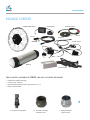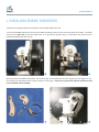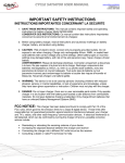
1
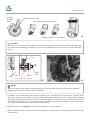
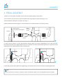
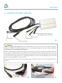
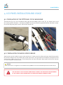
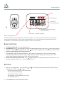
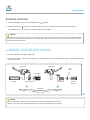
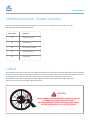
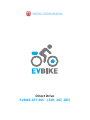
INSTALLATION MANUAL
Direct Drive
EVBIKE-SET-36V - (26R, 26F, 28F)
www.EVBIKE.cz
Dear Customer,
Congratulations on purchasing your EVBIKE. We believe that you will be fully satisfied with its operation.
The electric bike is one of the most economical means of transport with minimal operating costs. Mounting kit
EVBIKE is designed for converting your existing wheel bike to ebike.
EVBIKE kit is compatible with almost every mass produced bike. We always recommended, before installation, to
consult compatibility and amount of any adjustments, with your nearest EVBIKE service partner. The current
partners list can be found on the website www.evbike.cz, section "Partners".
It may happen that you dislike the product, or you have found in the manual a fact, which prevent you using of kit.
In that case please return kit before installing back, in original undamaged packaging.
For actual warranty terms and conditions and the possibility of returning, please contact your reseller who will
advise you on how to proceed. In case you do not do so, warranty defects resulting from improper use will not be
accepted.
We wish you many happy kilometers!
CAUTION
EVBIKE SET IS SOLD AS THE CONVERSION KIT. SAFETY AND COMPLIANCE WITH LEGISLATIVE
REQUIREMENTS OF THE FINAL PRODUCT IS FULLY GUARANTEED BY THE OPERATOR OF A BIKE
OR WHOEVER BUILT AND THAN SOLD THE CONVERSED BIKE. WE RECOMMEND THAT YOU
ENTRUST CONVERSION OF THE BIKE TO AN AUTHORIZED SERVICE CENTER.
PLEASE READ CAREFULLY THIS INSTALLATION MANUAL BEFORE YOU WILL START EVBIKE
CONVERSION.
www.EVBIKE.cz
TABLE OF CONTENTS
1. Changing of rim with motor
2. Pedal assistant
3. Controller and cabling
4. LCD panel instalation and usage
5. Brakes, accelerator, handle
6. Diagnostic of malfunctions and service
7. Usage
8. Maintenance
SPECIFICATIONS
Motor power:
Motor weight:
Maximum speed:
Driving range:
up to 500 W / 36 V (limited to 250 W)*
6,6 Kg
up to 30 km/h with pedal assistence (limited to 25 km/h)*
30 - 70 km - depending on pedalling intensity, nature of the terrain and used battery
type
Size and material of rim: 26" or 28" x 1,75", Alluminium alloy 6061, (double wall)
Maximum rim load:
50 - 70 kg, total bicycle load up to 120 kg must not be exceeded (includes the weight
of the rider, bike and EVBIKE set)
Drive:
front/rear
*Due to European laws for electric bikes, maximum speed is limited to 25 km/h. The limitation can be set off for
running at private roads etc.
www.EVBIKE.cz
PACKAGE CONTENT
EVBIKE HUB motor
LCD display
Sensor
Pedal assistant
Sensor
Magnet
Magnet
Brake levers
Accelerator
Battery
Controll unit
For succesful assembly of EVBIKE, you will also need following:
— ribbons for cables fastening
— screws, nuts, washers
— special bottom bracket tools (see pictures a, b, c)
— basic technical skills
1
a - Compact Crank Puller
b - Cassette Lockring
Remover Tool
c - Bottom bracket
remover tool
www.EVBIKE.cz
1. INSTALLING EVIBIKE HUB MOTOR
1) Remove the original wheel and swap tire to the EVBIKE HUB motor rim.
2) Insert the EVBIKE HUB motor into the fork. When installing, make sure the correct direction of rotation. The cable
come out on right side of the fork when bike is in the normal position (Fig. 3). Otherwise the wheel will run
backwards against direction of way.
2
3
Mounting of the rim differs bike to bike. For all bike types we recommend to use the torque arm. See Figures 2, 4, 5.
The torque arm will eliminate the reaction torque on axe (Fig. 6). Torque arm is partof the optional accessories and
is not included in basic package.
4
5
www.EVBIKE.cz
Direction
of engine
torque
Reaction torque on axle
Axle spinout and spread dropouts
Example of torque arm installation
6
CAUTION
In any case, it is necessary to ensure tight connection nuts, washers and fork surface. Insufficient nut tightening
may cause wheel dropping out of the fork. The connection between wheel and fork must be firm and stable
(Fig. 7).
Fork
Motor
Matice
spring washer (not included)
Engine
shaft
7
8
NOTICE
When you install the hub motor to the rear wheel (Fig. 8), proceed the same way. There are only following
differences between front and rear wheel installation.
●
In addition, you must dismount the freewheel shimano gears. To dismount the freewheel use a special pinion
puller (Fig. 1b). The rear hub motor is ready for mounting freewheel with screw pinion. For most bikes equipped
with 7 gears shimano wheel is a screw pinion. For bikes with 8 gears or more gears is not recommended to use the
rear hub motor because here is a potential of many complications during the installation. For bikes with 8 and
more gears we recommend to use the front wheel hub motor.
●
The cable come out on left side of rear fork when the bike is in normal position.
●
After installation the hub motor you will need to adjust the sorting of gears. Its needed to avoid a collision with
the hub motor.
www.EVBIKE.cz
2. PEDAL ASSISTANT
1) When you start pedal, the pedal assistant will automatically adjust motor power.
2) To install this part, you have to remove spindle. Removing requires special tools (Fig. 1a, 1c).
3) Disassemble the bike parts as shown at the Fig. 9.
4) Mout plastic wheel with magnets in correct direction of rotation (shown on wheel by arrows).
pedal assistant
plastic wheel with magnets
Crankset
spindle
pedal
assistant
sensor
pedal
bike frame
removable
ring
9
5) There must be about 2-5 mm space between plastic wheel and sensor. Depending on the type of bicycle,
the distance between the magnet wheel and sensor could be too small respectively large. Sensor ring sleeve can be
rotated and sensor bolted from the other side (Fig. 10).
2-5 mm
2-5 mm
10
6) Assembly all parts back. Before final tightening you should check the correct function of pedaling detection.
TIP
If you mount kit on a scooter, or operate it only in accelerator mode, you can skip pedal assistant assembly.
www.EVBIKE.cz
3. CONTROLLER AND CABLING
Main wire for control elements
(LCD display, brakes, accelerator)
Speed sensor
Pedal assistant
Battery power
11
Motor connector
WARNING
Make sure proper cable connection! Conectors have different colors so risk of incorrect connection is minimised
(Fig. 11). In addition, they have locks against turn over. Use adequate strength to connect connectors. If you use
excessive force, you may damage the connectors!
Before connecting cables to the controller, make sure that all the pins inside the connectors are properly seated. All
pins must be in straight direction to the opposite connector body. Before cable connecting, check the contacts and
make adjustments to ensure perfect contact pins with the opposite connector pins. Wrong cables or pins connecting
can cause serious damage of bike parts - especially the battery, motor and controller. Damages due the incorrect
cable or pins connecting will void your warranty
When connecting the motor connector and controller, make sure that the arrows on the connectors facing each other
(Fig. 13).
brake
accelerator
LCD displey
brake
12
13
www.EVBIKE.cz
4. LCD PANEL INSTALLATION AND USAGE
4.1. Installation of the LCD panel to the handlebar
The LCD panel (Fig. 18) can be installed on both sides of the handlebar (left or right, Fig. 14). Please have in mind
the correct position of buttons – the lettering "MODE" must be read from the perspective of the rider. After installation of the LCD panel please connect cable to the control unit.
m
14
m
2-5
15
4.2. Installation the wheel speed sensor
Speed sensor must be installed as near to the control unit. In most cases this will be to the rear wheel. Sensor attach
to the frame. Magnet must be installed close to the speed sensor. The optimal distance between the magnet and the
speed sensor is about 5 mm (Fig. 15). If the display does not show information about speed and distance, the error
is in the installation of speed sensor.
NOTICE
If the speed sensor or magnet are not installed correctly EVBIKE set turns off automatically 10 minutes after startup.
THE LCD PANEL IS FULLY FACTORY CONFIGURED TO MEET THE LEGISLATIVE REQUIREMENTS
OF THE E BIKES. SPEED IS REDUCED TO 25 KM/H AND ENGINE POWER TO 250W.
www.EVBIKE.cz
Timer
Actual speed
Power assist
up to 6 km/h (walk)
16
Daily ride distance (km per day)/
Total ride distance
Power level - the pedal assistantce
Battery voltage indicator
The battery indicator shows the approximate value of the voltage, not the capacity of the battery! When driving, battery
voltage changes and indicator can show a fully discharged battery. This is a normal phenomenon which depends on type
of the battery. For the real status of the battery voltage is necessary to stop the bike.
Basic functions
1. Turning the display ON - Press the MODE button.
and the display will show the MAX speed during this ride. Hold
again and the display
2. Speed Display. Hold
will show the AVG speed during this ride. Hold
again and the display will turn to the current speed display.
3. Distance Display (Riding Distance/Total Distance)
Press MODE for single trip and accumulate trip. This function is convenient for users to check the riding
distance (TRIP) and the total distance (ODO). Daily kilometers (TRIP) is always reset when you turn off the
display. Total kilometers (ODO) remain in the memory of LCD panel.
or change motor output power. Power level from 1 to 5, 1 is
4. Switch power and select speed mode. Press
lowest 5 is highest, default is 1, 0 - motor assistance is off.
Settings
and
1. Enter to the settings menu - press and hold
MODE button. Values set by and .
- You can set the curent time - hours and minutes
- The motor speed limit setting
- Units setting - MPH or Km/H
- Size od wheel in inches (default value is 26“).
- LCD backlight intensity
2. Press MODE again to leave the settings menu.
on the LCD controller. Swith between values pressing
www.EVBIKE.cz
Advanced functions:
1. The LCD backlight - press and hold MODE and
together
button will activate engine speed of 6 km/h. This feature can be used to start
2. Longer holding the
the EVBIKE in case you have not installed accelerator (throttle).
NOTICE
Activation of the LCD panel is required to operate the bike. After switching on the battery, press and hold the "MODE"
button that will display information on the LCD panel and the bike can be used. If you set engine power level to 0,
the pedal assistant is inactive.
5. BRAKES, ACCELERATOR, HANDLE
●
First disassemble the original equipment.
●
Controls assemble in this order see Figure 17. Accelerator and LCD can be installed on left or right side according
to user preference.
brake lever
brake lever
ring
spacer
LCD display
handle
accelerator
LCD controller
shorten
handle
handlebar
17
NOTICE
If you operate bike in pedal assistant mode you can skip the installation of accelerator.
Unused connector on the combined wiring harness must be insulated against moisture.
www.EVBIKE.cz
6 ERROR DIAGNOSTICS - TROUBLE SHOOTING
If there is something wrong with the electronic control system, the display will show the error code
automatically. Please the following table:
Code number
Definition
21
Abnormal current
22
Throttle fault
23
Motor phase problem
24
Motor Hall defect
25
Brake failed
7 USAGE
The product can be used in the rain, but should not be exposed to continuous contact with water. If you are driving
in the rain never disconnect connectors and do not use LCD controller. Don’t leave the main unit exposed to direct
sunlight when not riding the bike. Store the product in a dry place with a temperature of 15-25 °C.
Keep product clean. Don’t use thinner, alcohol or benzene. Wash with clean water using a damp cloth.
Do not concentrate on meter while riding. Safety first!
CAUTION
NEVER HANDLE WITH MOVING PARTS WHEN THE BATTERY
IS CONNECTED. RISK OF SERIOUSLY INJURY!
BEFORE HANDLING TURN OFF LCD DISPLAY, DISCONNECT
BATTERY AND REMOVE IT OUT OF THE HOLDER.
www.EVBIKE.cz
8 MAINTENANCE
It might seem that the EVBIKE set is almost maintenance free. Main care will definetely require your battery.
Please check separate battery user manual for more infromation. In this manual you can find only basic guidelines
how to use lithium batteries. If you follow this guidelines, you will ensure longer life of your battery.
The following principles apply to most types of lithium batteries.
Proper charging
Lithium cells which contain EVBIKE batteries can be recharged at any level of charge or discharge - these batteries
have no memory effect. We recommend always after the ride, to recharge the battery so you can immediately
enjoy full power and a long driving range. After recharge always unplug the battery from the charger.
Proper discharging
Recharge the battery to full capacity after the the first disconnection of protective controller. Never try to reuse
the battery after protective disconnection! Deep discharge of some cells and their unrepairable damage may
happen! Such battery usage may also cause unbalance of battery cells voltage and decrease their capacity.
In extreme cases, the battery can not be recharged again. This kind of damage can be easily diagnosed and will
result in avoiding your warranty.
Storage
If you do not use the bike for more than 1 hour, always disconnect the battery using its power switch. If you do not
use the bike for more than 24 hours, always remove the battery, recharge it and store in a safe dry place at room
temperature. Beware of short-circuit the battery terminals (contacts) when storing and handling. For long-term
storage, such as off-season, it is also necessary check battery every 14 days (using LEDs) and after 1 month
recharge the battery to its full capacity. If you do not perform this maintenance deep discharge of the battery cells
will occur. This irreparable battery damage is not covered by warranty.
BEFORE THE FIRST RIDE CHECK THE TIGHTNESS OF ALL BOLTS
AND FUNCTIONALITY OF ALL SYSTEMS INCLUDING WHEEL BRAKES.
Global World Logistic Ltd.,EU-VAT ID: CZ682998344, as legal entity authorized by manufacturer for EU, hereby
declares, that the device is in compliance with basic requirements and further relevant provisions of directive LOW
VOLTAGE DIRECTIVE 2006/95/EC which sets technical requirements for electric devices of low voltage.
This declaration is issued on documents provided by Manufacturer.
www.EVBIKE.cz