1
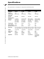
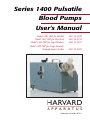
Series 1400 Pulsatile
Blood Pumps
User's Manual
Model 1405 PBP for Rabbits
Model 1407 PBP for Mice/Rats
Model 1421 PBP for Dogs/Monkeys
Model 1423 PBP for Large Animals;
Hemodynamic Studies
MA1 55-1838
MA1 52-9552
MA1 55-3321
MA1 55-3305
Publication 5413-001-REV-C
WEEE/RoHS Compliance Statement
EU Directives WEEE and RoHS
To Our Valued Customers:
We are committed to being a good corporate citizen. As part of that commitment,
we strive to maintain an environmentally conscious manufacturing operation. The
European Union (EU) has enacted two Directives, the first on product recycling
(Waste Electrical and Electronic Equipment, WEEE) and the second limiting the use
of certain substances (Restriction on the use of Hazardous Substances, RoHS).
Over time, these Directives will be implemented in the national laws of each EU
Member State.
Once the final national regulations have been put into place, recycling will be offered
for our products which are within the scope of the WEEE Directive. Products falling
under the scope of the WEEE Directive available for sale after August 13, 2005 will
be identified with a “wheelie bin” symbol.
Two Categories of products covered by the WEEE Directive are currently exempt
from the RoHS Directive – Category 8, medical devices (with the exception of
implanted or infected products) and Category 9, monitoring and control instruments.
Most of our products fall into either Category 8 or 9 and are currently exempt from
the RoHS Directive. We will continue to monitor the application of the RoHS
Directive to its products and will comply with any changes as they apply.
• Do Not Dispose Product with Municipal Waste
• Special Collection/Disposal Required
Table of Contents
Harvard Apparatus Series 1400 Pulsatile Blood Pumps User's Manual
1
SUBJECT
PAGE NO.
Warranty and Repair Information ........................2
Theory of Operation ..............................................3
Specifications ........................................................4
Operation:
Installing the Pump ............................................5
Operation for All Pumps ....................................5
Operating Controls:
Stroke Volume Adjustment ............................6
Rate Adjustment ............................................6
Output Phase Ratio........................................6
Dual Phase Rate Compensation Chart ..............7
Models 1405 & 1407:
Pumping Head ..............................................8
Cleaning and Sterilization ..............................8
Lubrication ....................................................8
Valves ............................................................8
Pump Mechanism ..........................................8
Models 1421 & 1423:
Pumping Head ..............................................9
Cleaning and Sterilization ..............................9
Lubrication ....................................................9
Valves ............................................................9
Pump Mechanism ..........................................9
Control ..........................................................9
Drawing and Parts List ..................................10-13
Diagrams ........................................................14-15
Data ......................................................................16
Publication 5413-001-REV-C
Warranty and Repair Information
2
Harvard Apparatus Series 1400 Pulsatile Blood Pumps User's Manual
Serial Numbers
All inquires concerning our product should refer to the serial number of the unit(s).
W a rr a n t y
Harvard Apparatus warranties the instrument(s) for a period of two years from date
of purchase.At its option, Harvard Apparatus will repair or replace the unit(s) if it is
found to be defective as to workmanship or material.
This warranty does not extend to damage resulting from misuse, neglect or abuse,
normal wear and tear, or accident.
This warranty extends only to the original customer purchaser.
IN NO EVENT SHALL HARVARD APPARATUS BE LIABLE FOR INCIDENTAL OR
CONSEQUENTIAL DAMAGES. Some states do not allow exclusion or limitation of
incidental or consequential damages so the above limitation or exclusion may not
apply to you. THERE ARE NO IMPLIED WARRANTIES OF MERCHANTABILITY,
OR FITNESS FOR A PARTICULAR USE, OR OF ANY OTHER NATURE. Some states
do not allow this limitation on an implied warranty, so the above limitation may not
apply to you.
If a defect arises within the two-year warranty period, promptly contact Harvard
Apparatus, Inc. 84 October Hill Road, Holliston, Massachusetts 01746-1371
using our U.S. only toll free number 1-800-272-2775 or dial (508) 893-8999. Goods
will not be accepted for return unless an RMA (returned materials authorization)
number has been issued by our customer service department. The customer is
responsible for shipping charges. Please allow a reasonable period of time for completion of repairs, replacement and return. If the unit is replaced, the replacement
unit is covered only for the remainder of the original warranty period dating from the
purchase of the original device.
This warranty gives you specific rights, and you may also have other rights which vary
from state to state.
R e p a i r F a c i l i t i e s a n d P a rt s
Harvard Apparatus stocks replacement and repair parts. When ordering, please
describe parts as completely as possible, preferably using our part numbers. If practical, enclose a sample or drawing.We offer a complete reconditioning service.
CAUTION: Not for clinical use on human patients.
Publication 5413-001-REV-C
Theory of Operation
Harvard Apparatus Series 1400 Pulsatile Blood Pumps User's Manual
3
This family of four pumps, all similar in concept but differing in capacity, are intended to pump blood with minimum damage to blood cells. All pumps feature a mechanically activated piston moving back and forth in a transparent cylinder. The geometry
of the piston actuation is such that the piston travels to the very end of the cylinder
regardless of the stroke volume selected. This feature insures that blood is completely
emptied from the cylinder at each stroke.
The valve cages and liquid pathway have been carefully designed to provide a streamlined flow with no sharp edge to minimize hemolysis.
All parts of the liquid pathway can be disassembled for cleaning and sterilization. In
all pumps the volume per stroke and the strokes per minute can be adjusted while
the pumps are running.
The two smaller pumps #1405 and #1407 have mechanically fixed systole/diastole
ratios of .33, that is, diastole lasts twice as long as systole. The larger pumps #1421
and #1423 have electronically variable ratios in which systole can be adjusted to be
25 to 50% of the total pumping cycle.
Publication 5413-001-REV-C
Specifications
4
Harvard Apparatus Series 1400 Pulsatile Blood Pumps User's Manual
The specifications of all pumps are compared in the following chart.
Harvard Pulsatile Blood Pump Comparison Chart
Catalog No.
52-9552
55-1838
55-3321
55-3305
Model No.
1407
1405
1421
1423
Stroke Volume
0.05 to 1.0 ml
0.5 to 10.0 ml
4 to 30 ml
15 to 100 ml
Stroke Rate
(per min)
20 to 200
20 to 200
20 to 200
10 to 100
Minimum Volume
(vol x rate)
1 to 200 ml
5 ml to 2.0 liters
80 ml to 6 liters
150 ml to 10 liters
Phasing
Fixed Phase
35% systole
65% diastole
Fixed Phase
35% systole
65% diastole
Adjustable Phase
35 to 50%
of total cycle
Adjustable Phase
35 to 50%
of total cycle
Tube Size (ID)
5/16 in
5/16 in
1/2 in
5/8 in
Piston Diameter
1/4 in
3/4 in
1-1/8 in
2 in
5/16 in
1/2 in
5/8 in
Ball Valve Diameter 5/16 in
Dimensions
312 x 156 x 250 mm 312 x 156 x 250 mm 500 x 212 x 337 mm 500 x 212 x 337 mm
(12.5 x 6.25 x 10 in) (12.5 x 6.25 x 10 in) (20 x 8.5 x 13.5 in) (20 x 8.5 x 13.5 in)
Weight
7.3 kg (16 lb)
7.3 kg (16 lb)
13.6 kg (30 lb)
14.5 kg (32 lb)
Power Used
50 W
50 W
85 W
85 W
Voltage
115/230 V
50-60 Hz
115/230 V
50-60 Hz
115 V
50-60 Hz
115 V
50-60 Hz
Application
Mice/Rats
Rabbits
Dogs/Monkeys
Large Animals;
Hemodynamic
Studies
Publication 5413-001-REV-C
Operation
5
Harvard Apparatus Series 1400 Pulsatile Blood Pumps User's Manual
Installing the Pump
Both of the smaller pumps #1405 and #1407 are equipped with a voltage selector
switch for either 120 or 220 volt usage. BE SURE THIS SWITCH IS SET FOR YOUR
VOLTAGE.
For 220 volt operation the American line cord plug must be cut-off and an appropriate plug installed. The line cord is color coded in International standard colors.
Brown – High
Blue – Neutral
Green – Ground
Observe these polarities. PUMPS ARE NOT EXPLOSION PROOF.
Operation for All Pumps
The inlet nozzle is always at the bottom of the pump head. Pumps are self-priming
and will lift liquids from reservoirs up to 50 centimeters below the inlet.
Since the valves of the pump are passive ball valves liquid will flow thru the pump
without the pump running if –
1.
2.
3.
The inlet reservoir is above the outlet
The inlet pressure is higher than the outlet pressure
The outlet tubing is below the inlet, this can cause siphoning or gravity
induced flow
The volume pumped per minute is called the “minute volume”. It is the product of
the stroke volume times the stroke rate. This is only valid if there is a normal amount
of back pressure or resistance to flow. Since the pumped liquid has inertia, liquid will
continue to flow even in the filling cycle. This can be prevented by having adequate
resistance in the output circuit.
Publication 5413-001-REV-C
Operation
6
Harvard Apparatus Series 1400 Pulsatile Blood Pumps User's Manual
O p e r a t i n g C o n t ro l s
Stroke Volume Adjustment
On smaller pumps the volume is set by turning the stroke volume control located at
the top of the pump. Volume is read from the decal fastened to the pump cylinder.
Volume is determined by watching the excursion of one “O” ring. Volume should be
adjusted while the pump is running. A thumb screw is built-in to the volume control
to provide positive locking once the volume is set.
On larger pumps the volume control is at the top while the actual volume is read
from a calibrated plate on the side of the pump. A locking knob next to the volume
pointer provides positive locking.
Rate Adjustment (strokes per min)
On small pumps the rate control is at the top of the pump, on large pumps the rate
control is at the end of the pump opposite the pump head.
Output Phase Ratio
The larger pumps are equipped with a control to adjust the ratio of systole to diastole. This control is located adjacent to the rate control. The control is continuously
variable from 25/75 to 50/50. In the 25/75 position, systole takes place in 25% of the
cardiac cycle while diastole takes place in 75%. This is observed by watching the piston/cylinder eject liquid quickly and fill slowly in the 25/75 position. In the 50/50
position the piston speed is the same in filling and emptying.
The phase ratio has an affect on the rate control (see figure 1 on next page). The
observed stroke rate varies considerably from the set rate as the phase ratio reaches
its outer limits.
Publication 5413-001-REV-C
Operation
50
50/50
45/55
40/60
35/65
30/70
40
Actual rate in strokes per min
Harvard Apparatus Series 1400 Pulsatile Blood Pumps User's Manual
7
25/75
30
20
10
0
0
10
20
30
40
50
Rate on strokes per min dial
Figure 1. Dual Phase Rate Compensation Chart.
Phase ratio (% systole); typical plot of actual stroke rate at various
ratios and strokes.
Publication 5413-001-REV-C
Operation: Models 1405 & 1407
8
Harvard Apparatus Series 1400 Pulsatile Blood Pumps User's Manual
C a re a n d M a i n t e n a n c e
Disconnect from the power source before performing any motor maintenance.
Pumping Head
The Pumping Head is easily removed for cleaning, sterilization and lubrication. Refer
to the diagram for part designation on the Standard 10 cc #1405 Pumping Head.
Follow the instructions below for removing the Head:
1.
2.
3.
4.
5.
Using the Stroke Rate and Stroke Volume Controls allow the Piston to recede to
the furthest end of its travel. (Note:The stroke volume control should be set for
maximum volume delivery).
Remove the thumbscrews attaching the cylinder and the valve head.
Gently pull the Cylinder away from the black plate until it clears the short binding posts extending from this plate.
Slide the Head and Cylinder assembly off the piston.
If Piston removal is desired, hold the Piston in one hand and use a small openend wrench to loosen the hex Coupling. The Piston can then be unscrewed
from the Coupling.
Cleaning and Sterilization
For non-sterile applications, clean parts from all residues with water and a damp
cloth. Flush the head and valves before reassembly to make sure that all cloth fibers
and other materials are cleared. For sterile applications, either gas or cold sterilization agents can be used.
Lubrication
Apply a light coating of the silicone grease provided to the Piston and the inside of
the Cylinder.
Valves
The Valves are easily disassembled for cleaning. The ‘O’ rings can be removed for
cleaning and replacement. Refer to the drawing when the components are to be
reassembled.
Pump Mechanism
The entire pump mechanism is available for inspection and lubrication by removing
the bottom cover and the control panel assembly. The bottom cover is removed by
loosening the screws within the four rubber feet. The control panel assembly is
removed by (1) loosening the set screw on the Stroke Volume Control and removing
the knob, (2) removing the eight Phillips-type screws connecting the panel assembly
to the housing, and (3) lifting the panel assembly clear of the stroke control shaft.
IMPORTANT: Make sure that the wires remain connected to their appropriate terminals. All bearings and points of frictional contact should be lubricated every 30
days with a light machine oil (Harvard Part No. 0606-060).
Publication 5413-001-REV-C
Operation: Models 1421 & 1423
9
Harvard Apparatus Series 1400 Pulsatile Blood Pumps User's Manual
C a re a n d M a i n t e n a n c e
Disconnect from the power source before performing any motor maintenance.
Pumping Head
The Pump Head is easily removed for cleaning, sterilization, and lubrication. Refer to
diagrams for part designation on the #1421 and #1423 Pumping Heads, respectively.
Follow the instructions below for removing the head:
1.
2.
3.
Using the spanner wrench provided, insert the wrench-pin into one of the holes
in the Nut-Coupling, apply pressure, and loosen. The coupling can now be easily removed from the cylinder.
Using the same wrench, insert the wrench-pin into one of the holes on the cylinder, apply pressure, and loosen. Proceed to unscrew the cylinder manually.
To remove the Piston, insert the wrench-pin into one of the holes on the Piston,
apply pressure, and loosen. Remove the Piston manually.
Cleaning and Sterilization
For non-sterile applications, clean parts from all residues with water and a damp
cloth. Make certain that all cloth fibers are cleared from the system before it is
reassembled. For sterile applications, either gas or cold sterilization agents can be
used.
Lubrication
Apply a light coating of the silicone grease provided to the Piston and the inside of
the Cylinder.
Valves
The Valves are easily disassembled for cleaning. The ‘O’ rings can be removed for
cleaning and replacement. Refer to the drawing when the components are to be
reassembled.
Pump Mechanism
The entire Pump Mechanism is available for inspection and lubrication by removing
the blank side panel. All bearings and points of frictional contact should be lubricated every 30 days with a light machine oil (Harvard Part No. 0606-060).
Control
The solid state dual phase Motor Control needs no special attention. If a problem
seems to exist in the motor control, the unit should only be examined by a qualified
technician. A safety fuse (1 amp. slo-blo type) is provided for overload protection. DO
NOT REPLACE with a higher rated fuse.
Publication 5413-001-REV-C
Drawing and Parts List (1 cc)
10
Harvard Apparatus Series 1400 Pulsatile Blood Pumps User's Manual
1 c c S t a n d a rd P u m p i n g H e a d / 5 2 - 9 5 5 2 / 1 4 0 7
1405-046
5013-034
1405-043
1407-012
1407-013
1405-044
0
.5
1
0680-067
5013-016
5011-019
1405-045
Publication 5413-001-REV-C
Part No.
Replacement Part
0680-067
Coupling
1407-013
Piston
1405-044
Body–Valve
1405-045
Nozzle–Suction
1407-012
Cylinder
1405-046
Nozzle–Discharge
5011-019
Ball–SS Bearing, Hard
5013-016
O Ring, Parker #0125-070
5013-019
O Ring, Parker #2-13
1405-043
Head
Drawing and Parts List (10 cc)
11
Harvard Apparatus Series 1400 Pulsatile Blood Pumps User's Manual
1 0 c c S t a n d a rd P u m p i n g H e a d / 5 5 - 1 8 3 8 / 1 4 0 5
1405-046
5013-034
1405-042
1405-011
1405-010
1405-044
0
.5
10
0680-067
5013-018
5011-019
1405-045
Publication 5413-001-REV-C
Part No.
Replacement Part
0680-067
Coupling
1405-010
Piston
1405-044
Body–Valve
1405-045
Nozzle–Suction
1405-046
Nozzle–Discharge
1405-042
Assy–Valve HD & Cylinder
5011-019
Ball–SS Bearing, Hard
5013-018
O Ring, Parker #2-16
5013-019
O Ring, Parker #2-13
Drawing and Parts List (30 cc)
12
Harvard Apparatus Series 1400 Pulsatile Blood Pumps User's Manual
3 0 c c S t a n d a rd P u m p i n g H e a d / 5 5 - 3 3 2 1 / 1 4 2 1
1401-033
5013-021
1401-010
5013-014
1401-014
5115-011
1401-032
1401-030
1401-015
1401-008
5124-001
1401-031
Publication 5413-001-REV-C
5013-032
Part No.
Replacement Part
1401-008
Cylinder
1401-030
Head–Valve
1401-010
Nut–Coupling
1401-031
Nozzle–Suction
1401-032
Body–Valve
1401-033
Nozzle–Discharge
1401-014
Piston
1401-015
Shaft–Connecting
5013-014
O Ring, Parker #2-126
5013-021
O Ring, Parker #2-18
5013-032
O Ring, Parker #2-119
5115-011
Set Screw #8, 32 x 3/16
5124-001
Sphere, 1/2 D
Drawing and Parts List (100 cc)
13
Harvard Apparatus Series 1400 Pulsatile Blood Pumps User's Manual
1 0 0 c c S t a n d a rd P u m p i n g H e a d / 5 5 - 3 3 0 5 / 1 4 2 3
1403-022
5013-037
1403-010
5013-028
1403-014
5115-011
1403-021
1403-019
1403-015
1403-008
5013-029
5124-002
1403-020
Publication 5413-001-REV-C
Part No.
Replacement Part
1403-008
Cylinder
1403-019
Head–Valve
1403-010
Nut–Coupling
1403-020
Nozzle–Suction
1403-021
Body–Valve
1403-022
Nozzle–Discharge
1403-014
Piston
1401-015
Shaft–Connecting
5013-028
O Ring, Parker #2-140
5013-029
O Ring, Parker #2-133
5013-037
O Ring, Parker #2-24
5115-011
Set Screw #8, 32 x 3/16
5124-002
Sphere, 3/4 D
Diagrams
14
Harvard Apparatus Series 1400 Pulsatile Blood Pumps User's Manual
Ty p i c a l P u m p H e a d
Output
Polycarbonate
Nozzle
Transparent Acrylic
Valvecage
Teflon Coated
Piston
Transparent
Acrylic Chamber
Transparent
Acrylic Cylinder
Silicone
Ball-Check
Valves
Fluoro Elastomer
“O” Rings
Aluminum
Coupling Nut
Input
Publication 5413-001-REV-C
Publication 5413-001-REV-C
Model No.
1405
1421
1421A
1423
1423A
1407
55-1838
55-3321
55-3339
55-3305
55-3313
52-9552
GROUND LUG
MAIN CHASIS
BLUE #18
Catalog No.
GROUND LUG
FRONT PANEL
GREEN #18
GREEN/YELLOW #18
W1
PLUG AC MALE
BROWN #18
F1
FUSE SLOW BLOW
WHITE #18
115/240 VAC, 50–60 Hz (1 AMP)
240 VAC, 50 Hz (1/2 AMP)
115 VAC, 60 Hz (1 AMP)
240 VAC, 50 Hz (1/2 AMP)
115 VAC, 60 Hz (1 AMP)
115/240 VAC, 50–60 Hz (1 AMP)
Power
S1
POWER SWITCH
BLACK
BLACK
PILOT LIGHT
DS1
BLACK #18
BLACK
100K
SPEED
GREEN
VR101
RED
L1
S1
S2
S3
L1
L2
A1
F1
BLUE #18
BLUE #18
A2
MC1
F2
M1
MOTOR
BLACK #18
BLACK #18
Harvard Apparatus Series 1400 Pulsatile Blood Pumps User's Manual
Diagrams
15
S i n g l e P h a s e M o t o r S p e e d C o n t ro l
(Models 1405 & 1407)
Data
16
Harvard Apparatus Series 1400 Pulsatile Blood Pumps User's Manual
H e m o l y s i s Te s t D a t a ( M o d e l s 1 4 2 1 & 1 4 2 3 )
In these studies a reservoir of 500 to 800 cc of fresh dog blood was used, connected
to the pump by 3/8" PVC tubing. Samples at room temperature were taken at 15 and
30 minute intervals for 4 to 5 hours. Samples were spun down and hemolysis measured immediately using the method of FLINK & WATSON. Since the rate of hemolysis depends on the amount of blood in the system and the flow rate, the results are
reported as mg % per pass. The flow rate divided by the volume of blood in the system determines the number of passes through the pump per minute.
Hemolysis ranged from 0.114 mg % to 0.27 mg % per hour pass through the various
pumps with an error of ± 10%.
To put these results in perspective most physiological perfusions are run with flow
rates and total blood primes, so that the number of passes through the pump will
range from about 1/4 to 3/4 per minute. Assuming one pass in two minutes and no
physiological removal of the products of hemolysis, then hemolysis rates would range
from 3.4 mg % to 8.7 mg % per hour of pump use.
Publication 5413-001-REV-C